Note: Descriptions are shown in the official language in which they were submitted.
CA 02249910 1998-10-09
-1-
HIGH EFFICENCY, GLASS-LINED, COMBINATION
SPACE AND HOT WATER HEATER
TECHNICAL FIELD
s The present invention relates to a high efficiency
glass-lined combination space and hot water heater provided
with a closed circulating circuit through which a
predetermined volume of water is circulated and maintained
within the tank. The combination heater of the present
1o invention substantially prevents the build-up of deposits
and corrosion. Accordingly, a high constant efficiency
heater is achieved and the life expectancy of the heater is
substantially prolonged. The hot water heater of the
present invention provides both space heating and potable
15 domestic hot water.
BACKGROUND ART
Indirect water heaters are well known in the art
wherein a coil is placed within a hot water tank to which
zo city water is fed at one end of the coil and exits at the
other end to feed a domestic hot water supply. The hot
water within the tank is also fed city water which is heated
and used for domestic application such as washing or
bathing, whereas the water within the coil is used for
zs consumption or other specific applications such as for
heating baseboards connected to a water convection circuit.
With glass-lined water heaters which are continuously fed
city water, the reservoir and heating coil is continuously
bombarded with deposits including calcium, silicas, silts
3o and ferrous materials. This causes several problems such as
the formation of bacteria within the coil of the radiators
when the water is stagnant therein. In radiators, the water
could be stagnant for long periods of time as these are not
utilized during the summer months. Accordingly, bacteria
3s will build up during the hot summer months and when the
system is placed back in use, these bacterias are flushed
CA 02249910 1998-10-09
-2-
back into the tank. If the water within the tank is
utilized for bathing or other use where the human body is in
contact with such water, then this contaminated water could
inflict serious disease to the user. Legionella is known to
s occur if stagnant water is mixed with potable water. This
can occur in summer months when water is stagnant in old
tasted water heaters which are disposed in hot rooms and
exposed to direct sunlight. If such stagnant water is mixed
with potable water it could prove deadly to human beings.
~o This risk is amplified if the city water does not contain
the proper quantity of chlorine. A further disadvantage is
that the build-up of calcium on the glass-lined surface as
well as the heat transfer surface and coils greatly affects
the efficiency of the heater.
~5 U.S. Patent 5,165,472 describes a heat exchanger
having fluid injectors therein to maintain the hot water in
continuous agitation and this has been found suitable to
prevent the formation of deposits on the glass lining of the
tank as well as on the heat transfer coils. However,
zo because the system is fed fresh water, deposits and water
contamination problems will occur in the heating radiators.
The patent is more concerned with the elimination of dead
zones or dead spots which cause sediment deposits. A further
disadvantage is that these systems corrode the copper pipes
z5 due to the use of acid water which contains C02 and these
copper pipes can deteriorate within short periods of time
such as five years. Accordingly, such heaters cannot be
adapted to old radiator systems which are more fragile and
which require hot water in the range of 190°F-200°F.
3o Combination water heating and space heating
apparatus utilizing the hot water from the same tank is
described in U.S. Patent 5,544,645. As described the water
heating unit and the space heating unit are coordinately
controlled such that priority is given to the potable hot
3s water supply over space heating in the event that sufficient
hot water is not available to satisfy both demands.
CA 02249910 1998-10-09
_3_
Accordingly, all of the above-mentioned disadvantages of the
prior art are exemplified by this type of apparatus. A still
further example of a combination water heating and space
heating apparatus is described in U.S. Patent 4,222,350.
SUMMARY OF INVENTION
It is a feature of the present invention to
provide a high efficiency, glass-lined, combination space
and hot water heater which substantially overcomes the
to above-mentioned disadvantages of the prior art and wherein
life-expectancy is greatly improved.
Another feature of the present invention is to
provide a high efficiency, glass-lined, combination space
and hot water heater having a closed water circulating
~s circuit connected to radiators for producing heat and
wherein the water consists of a predetermined volume which
is continuously circulated during use and wherein the water
is substantially free of sedimentary, corrosive and other
harmful products.
zo Another feature of the present invention is to
provide a high efficiency, glass-lined, combination space
and hot water heater having one or more heat exchange coils
therein in contact with the hot water for producing domestic
hot water independently of the water circulated in the
zs closed circuit.
Another feature of the present invention is to
provide a high efficiency, glass-lined combination space and
hot water heater providing substantially unobstructed heat
transfer and having a longer life expectancy than prior art
3o water heaters for such use.
According to the above features, from a broad
aspect, the present invention provides a high efficiency,
glass-lined, combination space and hot water heater which
comprises an inner tank. An outer casing is spaced about
35 the inner tank and insulation is provided between the outer
casing and the inner tank. The inner tank has a glass-lined
CA 02249910 1998-10-09
- 4 -
inner surface. Heater means is provided for heating a
predetermined volume of water within the inner tank. An
anode extends within the inner tank. A closed water
circulating circuit is connected to the inner tank for
s circulating hot water from the inner tank. Heat exchange
means is connected in the closed water circulating circuit.
A pump is connected to the closed water circulating circuit
for convecting hot water from the inner tank through the
heat exchange means. The predetermined volume of
~o recirculating water provides for minimal deposits to
accumulate in the inner tank thereby substantially
preventing the build-up of deposits on heat exchange
elements within the tank and the formation of harmful
bacteria and corrosion and further wherein high constant
efficiency is achieved and the life expectancy of the hot
water heater is substantially prolonged. At least one heat
exchange coil is disposed in the inner tank and immersed in
the water contained therein. The heat exchange coil is
connected at one end to an outlet coupling to which a
2o domestic hot water line is connected. An opposed end of the
heat exchange coil is connected to an inlet coupling. The
inlet coupling is connected to a pressurized water supply.
BRIEF DESCRIPTION OF DRAWINGS
zs A preferred embodiment of the present invention
will now be described with reference to the examples thereof
as illustrated in the accompanying drawings in which:
FIG. 1 is a cross-sectional schematic view of a
high efficiency, glass-lined, combination space and hot
3o water heater using a gas or oil burner and constructed in
accordance with the present invention and connected to a
closed loop water circulating circuit and illustrating the
optional use of one or more heat exchange coils provided in
the inner tank to supply hot domestic water;
35 FIG. 2 is a section view showing the disposition
of the one or more heat exchange coils;
CA 02249910 1998-10-09
FIG. 3 is another cross-sectional schematic view
of a high efficiency, glass-lined, combination space and hot
water heater constructed in accordance with the present
invention and wherein the heating means is constituted by
s electric resistive elements;
FIG. 4 is a fragmented perspective view showing
an agitating conduit disposed adjacent the bottom wall of
the water heater for agitating the hot water therein; and
FIG. 5 is a section view illustrating a still
~o further embodiment of the present invention.
DESCRIPTION OF PREFERRED EMBODIMENTS
Referring to the drawings and more particularly to
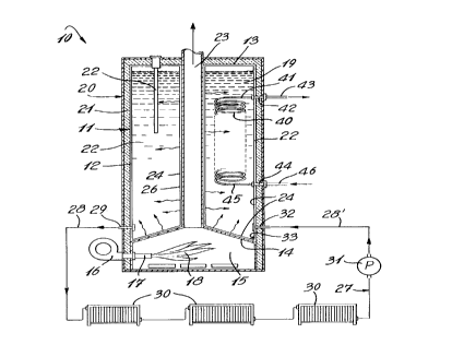
Figure 1, there is shown generally at 10 one example of a
15 high efficiency, glass-lined, combination space and hot
water heater constructed in accordance with the present
invention. It consists essentially of an inner tank 11
having a cylindrical side wall 12, a top wall 13 and a
bottom wall 14. A combustion chamber 15 is provided below
zo the bottom wall. A gas or oil burner 16 is connected to the
side wall and has a combustion nozzle 17 extending within
the combustion chamber 15 to produce a flame 18 therein to
provide a heat source to heat the same predetermined volume
of water 19 contained within the inner casing 12. The tank
z5 11 is not continuously fed by the city water supply and
accordingly does not use fresh water which contains
sedimentary particles.
An outer casing 20 is secured about the inner
casing 11 and an insulating material, such as wool or foam
3o insulation 21 is disposed between the outer wall of the
inner tank and the inner surface of the outer casing. An
anode 22 is secured in the inner casing and extends within
the inner chamber 22 in contact with the water 19 contained
therein, to protect the tank from the corrosive effects of
35 hot water, as is well known in the art.
CA 02249910 1998-10-09
-6-
As hereinshown a flue pipe 23 extends from the
combustion chamber 15 and exits through the top wall 13 of
the tank to release products of combustion into outside
atmosphere. The inner side wall as well as the inner
s surface of the bottom wall 14 of the tank are lined with a
glass lining 24, as is also well known in the art. The flue
pipe 23 also has a glass lining 24 thereabout and the top
wall 13 may also be glass-lined. As hereinshown the same
predetermined volume of water 19 within the inner chamber 22
~o is heated by heat transfer between the bottom wall 14 and
the cylindrical side wall 26 of the flue pipe 23.
A low-pressure closed water circulating circuit 27
operating within the range of from about 5 to 35 psi is
connected to the inner tank 11 and it consists of a conduit
~s 28 usually constituted by copper piping connected to an
outlet coupling 29. One or more heat exchange means, herein
baseboard heaters or radiators 30, are secured to the closed
circuit either in series, as hereinshown, or in parallel, so
that the hot water from the inner chamber 22 of the inner
2o tank is convected therethrough to generate heat to warm a
space. A pump 31 circulates the water within the closed
water circulating circuit 27 with the return conduit 28'
being connected to the inlet coupling 32.
It is important to note that the inner chamber 22
zs contains the same predetermined volume of water which is
continuously heated and recirculated. Therefore, fresh
water is not continuously added to the inner tank. The
advantage of this is that a predetermined small volume of
deposits will take place when the heater is initially placed
3o in use and small deposit only may accumulate in the corners
33 between the cylindrical side wall 12 of the inner tank
and the bottom wall 14 and will substantially not interfere
with the heat transfer surfaces. If fresh water was
admitted in the inner tank the sedimentary deposits would
3s continue to build up over the bottom wall and greatly reduce
the efficiency of this heat transfer. Also, hard fresh
CA 02249910 1998-10-09
-7-
water is known to have sedimentary material such as calcium,
silicas, silts and ferrous materials and some of these
products cause oxidation of exposed metal even through a pin
hole in the glass lining. The anode 22 substantially
s reduces this corrosive effect but seeing that the volume of
water is always the same volume, it cleanses itself and the
chance of corrosion taking place is practically eliminated.
Also, if harmful bacteria was to originate in the radiators
30 during stagnant periods, these bacterial would have no
~o effect on the potable heated water which is not mixed with
the volume of water in the tank. Usually, known combo
systems have a life expenctancy of 5-6 years whereas with
the present invention the life expectancy is extended to
about from 25-35 years.
In the specific embodiment as shown in Figure l,
domestic hot water is supplied by providing one or more,
herein four, heat exchange coils 40 as shown in Figures 1
and 2. These heat exchange coils are immersed in the
predetermined volume of hot water contained within the inner
zo chamber 22. The coils 40 are connected at one end, herein
41, to an outlet coupling 42 to which a domestic hot water
line 43 is connected. An inlet coupling 44, to which an
opposed end 45 of the heat exchange coils 40 is connected,
supplies pressurized water from the city supply conduit 46
zs which is pressured at about 65 psi . Because of the use of
the same predetermined volume of hot water, there will not
be any build-up of deposits on the heat exchange coils 40
and substantially 100% heat transfer is achieved. This
permits for a supply of hot domestic water at a constant
3o temperature and at high efficiency per b.t.u. Accordingly,
the hot water heater of the present invention can be adapted
to old steel-casted radiators where there is a need to
supply hot water at constant high temperatures in the range
of from about 190° to 200°F. If one of the coils was to
35 puncture, then the potable water would flow into the tank
due to the difference in pressure. This would cause the
CA 02249910 1998-10-09
_g_
relief valve of the tank to release water indication that a
coil is defective and the coil assembly would be changed or
else the combo unit replaced if it has been in operation up
to its life expectancy.
s Figure 3 illustrates a further embodiment of the
high efficiency, glass-lined hot water heater 10' of the
present invention. As hereinshown, the heat source is
provided by one or more, herein four, electric resistive
heating elements 50 extending within the inner chamber 22'
~o of the inner tank 11'. Although not shown the inner tank is
protected by an outer casing and insulation as shown in
Figure 1. The closed water circulating circuit 27' is
similarly connected to the inner chamber 22' of the inner
tank 11' as with the embodiment described in Figure 1. A
15 plurality of heat exchange coils 40' may also be
conveniently disposed within the inner chamber 22' to feed
the domestic hot water supply line 43'.
If desirable to enhance heat transfer, there may
be provided at the bottom of the inner tank 11 or 11' an
2o agitating means in the form of a partly circular conduit
like chamber 55 provided with orifices 56 therein oriented
at predetermined angles to agitate the water within the
inner chamber 22 or 22'. This agitating chamber would be
connected to the return line 28' of the closed water
zs circulating circuit 27 as shown in Figure 1. A similar
agitating means is described in U.S. Patent 5,165,472
referred to hereinabove and is shown herein as an auxiliary
or optional device that may be connected at the base of the
inner tank to obtain some of the benefits as described in
3o the aforesaid patent.
Referring to Figure 5 there is shown a still
further embodiment of the high efficiency combination space
and hot water heater of the present invention and generally
indicated by reference numeral 10". As hereinshown the
35 water heater is a gas heater provided with a combustion
chamber 60 at the base thereof adjacent the bottom wall 61
CA 02249910 1998-10-09
-9-
whereby to provide heat to heat the water contained within
the inner tank 11". A heat exchange coil 62 is wound along
a major portion of the flue pipe 63 and has an inlet end 62'
and an outlet end 62" exiting from the top of the tank. The
s inlet end 62' connects to the base portion of the heat
exchange coil 62 so that the potable water as it enters the
coil is heated as it is connected spirally from the base of
the hot water heater to the top portion of the hot water
heater.
~o A tubular sleeve 64 is formed about at least a
major portion of the heat exchange coil 62 and spaced from
the flue pipe 63 to define an annular jacket about the flue
pipe to retain heat, thus acting as a super heater. The
base of the tubular sleeve 64 is provided with a skirt
15 portion 65 which is spaced above the bottom wall 61 to
channel the water heated against the bottom wall 61 into the
annular jacket. The tubular sleeve 64 is spaced a
predetermined distance to provide for the water to shoot up
into this annular jacket, thus providing an upward
zo convection of hot water from the bottom wall 61 to the top
portion 66 of the inner tank 11". The water temperature at
the bottom portion of the tank is at about 140°F and at the
top it rises to about 175°F.
As hereinshown a further spiral heat exchange coil
zs 67 can be supported horizontally in the top portion 66 of
the inner tank 11" and connected to the inlet and outlet
pipes 62 ' and 62 " whereby to extract further heat from the
hot water within the tank and particularly in the top
portion 66 where the water is hotter than in the bottom
so section when the closed water circulating circuit 27 is not
in use. When the pump 31 is operated to circulate hot water
through the closed circulating circuit, then the water
temperature in the tank is fairly constant throughout the
tank.
35 The inlet coupling 32' connected to the inner tank
could also be located in a lower portion as indicated by
CA 02249910 1998-10-09
- 10 -
reference numeral 68 and have an extension pipe 69 extending
within the inner tank 11' and directly under the annular
skirt 65 so that the cooled return water from the closed
circuit can be warmed quickly as it moves up into the
annular jacket where it is superheated.
This particular embodiment as shown in Figure 5
for use with gas or oil burners has been found to be
extremely efficient as a combination space and hot water
heater.
to Those skilled in the art will appreciate that the
conception upon which this disclosure is based may readily
be utilized as a basis for the designing of other structures
and systems for carrying out the several purposes of the
present invention. It is important, therefore, that the
~s claims be regarded as including such equivalent
constructions insofar as they do not depart from the spirit
and scope of the present invention.