Note: Descriptions are shown in the official language in which they were submitted.
CA 02249941 1998-10-09
CONTROL APPARATUS FOR CONVEYOR
OF PARTICULATE MATERIAL
FIELD OF THE INVENTION
The present invention relates to a device which attaches to a conveyor belt
and which
controls the conveyance of particulate matter along such belt.
BACKGROUND OF THE INVENTION
Conveyors for moving particulate material such as stone, sand or gravel can be
found in
various applications. A truck with a conveyor apparatus as known in the art is
disclosed in U.S.
patent no. 5,190,432. This patent discloses an optional attachment for a
standard dump truck
that includes a swing arm, pivotally connected to the truck's chassis, an
elongated frame
pivotally connected to the swing arm and mounting an endless conveyor belt.
Another application where conveyors are used to move particulate material is a
stone
slinger. A stone slinger includes a first conveyor that receives material from
a hopper, which is
located behind the cab of a truck. The first conveyor moves the material onto
a second
conveyor. The second conveyor then sprays the material from the back end of
the truck.
Stone slingers are used so that the particulate material can be projected from
the rear of a
dump truck or similar device to a desired location. The slinger has a limited
dispensing range
that is determined by the speed of the conveyor.
Material is usually dumped onto the conveyor from a hopper or another
conveyor. The
method in which the material is loaded onto the conveyor from the truck causes
it to bounce
along the conveyor rather than rest on it. This can cause some material to be
projected from the
conveyor prematurely in all directions. This creates a hazard to anyone
standing in the vicinity
of the slinger. An increase in the conveyor speed causes further erratic
discharge of material.
Therefore, the speed of the conveyor is limited thereby limiting the discharge
range of the
stinger.
Some attempts have been made to control the premature and erratic discharge of
material
from the conveyor. In one such method, the material is sandwiched between the
conveyor belt
and a cover that is made of relatively light material such as sheet metal. The
cover lies flat on
-2-
CA 02249941 2002-04-16
3
the belt, while maintaining its horizontal position, and is temporarily
displaced as the material
passes underneath it. This method does not effectively control the erratic and
premature
discharge of material.
Thus, a need exists for a device for controlling the erratic dispersion of
particulate
material being conveyed on a conveyor belt. Such a device would reduce any
impediment in
increasing the speed of the conveyor belt and, thereby, allow material to be
ejected farther.
SUMMARY OF THE INVENTION
In general terms, the present invention provides, in one embodiment, an
apparatus for
controlling the conveyance of particulate material on a first conveyor belt,
the first conveyor
being driven by a driving means, the apparatus comprising:
a) a frame having at least one longitudinal member;
b) at least two rotating elements spaced apart along the frame; and,
c) an endless belt extending around the rotating elements;
the apparatus being positioned above and proximal to the first conveyor,
wherein the
endless belt extends along a portion of the first conveyor and wherein the
particulate material
flows between the endless belt and the first conveyor and whereby the endless
belt is frictionally
driven by the first conveyor belt.
- 3 -
_. _...._. .... ~_ _
f4
CA 02249941 2002-04-16
In another embodiment, the invention also provides a system for discharging
material
from a vehicle, the system comprising:
- a material holding container mounted on the vehicle;
- a first conveyor mounted on the vehicle to receive and convey the material
from
the container;
- a drive means provided on the vehicle for driving the first conveyor;
- an apparatus for controlling the conveyance of the material on the first
conveyor
comprising:
a) a frame having at least one longitudinal member;
b) at least two rotating elements spaced apart along the frame; and
c) an endless belt extending around the rotating elements;
- wherein the apparatus is positionable above and proximal to the first
conveyor,
and wherein the endless belt extends along a portion of the first conveyor and
wherein the
particulate material flows between and in contact with the endless belt and
the; first conveyor;
and wherein endless belt is frictionally driven by the first conveyor.
In another embodiment, the invention provides a vehicle for carrying and
discharging
material, the vehicle including:
- a material holding container mounted on the vehicle;
- a first conveyor mounted on the vehicle to receive and convey the material
from
the container;
- a drive means provided on the vehicle for driving the first conveyor;
- an apparatus for controlling the conveyance of the material on the first
conveyor
comprising:
a) a frame having at least one longitudinal member;
b) at least two rotating elements spaced apart along the frame; and
c) an endless belt extending around the rotating elements;
- wherein the apparatus is positionable above and proximal to t:he first
conveyor,
and wherein the endless belt extends along a portion of the first conveyor and
wherein the
particulate material flows between and in contact with the endless belt and
the; first conveyor;
and wherein endless belt is fractionally driven by the first conveyor.
-3a-
~i
CA 02249941 2002-04-16
In yet another embodiment, the invention provides a system for discharging
material
from one location to another comprising:
- a first conveyor for receive and convey the material between the locations;
- a drive means for driving the first conveyor; and
- an apparatus for controlling the conveyance of the material on the first
conveyor comprising:
a) a frame having at least one longitudinal member;
b) at least two rotating elements spaced apart along the frame; and
c) an endless belt extending around the rotating elements;
- wherein the apparatus is positionable above and proximal to the first
conveyor, and wherein the endless belt extends along a portion of the first
conveyor and
wherein the material flows between and in contact with the endless belt anal
the first
conveyor;
and wherein endless belt is fractionally driven by the first conveyor.
BRIEF DESCRIPTION OF THE DRAWINGS
These and other features of the preferred embodiments of the invention will
become
more apparent in the following detailed description in which reference is made
to the
appended drawings wherein:
Figure 1 shows a stone stinger truck in accordance with the prior art with a
safety
apparatus
Figure 2 is a side view of a safety apparatus in accordance with an embodiment
of the
invention
Figure 3 is a front view of the apparatus of figure 2
Figure 4 is a detailed view of the apparatus of figure 2
Figure 5 is a view on A-A of figure 4
-3b-
CA 02249941 1998-10-09
DESCRIPTION OF THE PREFERRED EMBODIMENTS
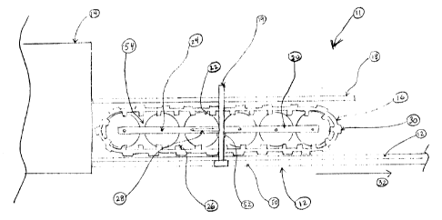
Refernng to figure 1, a prior art stone stinger truck is generally shown at
10. The truck
includes an endless thrower belt 12, that is attached to the vehicle and is
supported by a frame
50. The truck includes a drive means (not shown) to power the belt so as to
move particulate
material (not shown) deposited onto the belt from the truck bed 14 or from a
hopper. Material
may be deposited onto the belt directly from the truck bed 14 or an additional
conveyor 54 may
operate between the truck bed 14 and the belt 12 to transfer the material. The
thrower belt 12
may be either smooth or ribbed.
Refernng to figure 2, the apparatus of the invention is generally shown at 11.
The
apparatus includes an endless belt 16 located above the thrower belt 12 and
adjacent to the outlet
of the truck bed or hopper 14. In a preferred embodiment the endless belt 16
is approximately
the same width as the thrower belt 12. In one embodiment, the endless belt 16
has ribs 30
located on the outer surface thereof and that run transverse to the direction
of travel 32. The ribs
30 assist in fractionally engaging the endless belt 16 and the thrower belt
12. When the thrower
belt 12 is in motion it drives the endless belt 16 as a result of the
frictional engagement between
the belts 12 and 16. In another embodiment, the endless belt 16 may be smooth
while still
maintaining the frictional engagement with the thrower belt 12. The frictional
engagement may
result from direct contact between the belts 12 and 16 or indirect contact,
where the particulate
material that is passing between the belts 12 and 16 transfers the motion from
the thrower belt 12
to the endless belt 16.
The endless belt 16 extends around at least two pairs of wheels 22 rotatably
attached to
axles 24 mounted on opposite ends of a frame 54 which preferably comprises two
longitudinal
frame rails 20 extending along the length of endless belt 16. In a preferred
embodiment, the
apparatus of the invention includes a plurality of pairs of wheels 22
positioned along the length
of the belt 16 so as to provide adequate support therefor. The number of
additional wheels 22
and axles 24 between the ends of the endless belt 16 will vary depending on
the size of the
endless belt 16. In another embodiment, the wheels may be replaced with
rollers. In yet another
embodiment, the frame rails 20 may be replaced by a single longitudinal frame
rail 20.
In a preferred embodiment, the endless belt 16 includes two rows of inner
knobs 26
provided on the inner surface of the belt and along the length thereof. The
knobs 26 are arranged
so as to form two channels running longitudinally along the belt thereby
providing a groove for
-4-
CA 02249941 2002-O1-30
the wheels 22. The channels formed by the knobs 26 thereby servo to mtaintain
the belt in
alignment with the wheels. It will be appreciated that various other
arrangametits are possible
for maintaining the belt 15 in the desired alip~ment.
In a further preferred errtboditnent, the apparatus of the invention, 11, is
kept from
moving in the direction of travel 32 by a pivoting linkage 28. The linkage can
be attached to any
stationary part o~tbe slinger such as the frame S0. The other end of the
linkage 28 is attached to
the side rails 20, It will be apparent that any other attachment means may be
used.
In a further preferred embodiment, a support 19 may be detachably fixed to the
frame 50,
'The support i5 X1-shaped and extends across the top of the apparatus 11 and
attaches to the &am~
l0 50 on both sides. In a preferred embodiment, depth stops, or ledges, 52 are
located on either side
Qf the support 19 adjacent to the frame rails 20. The depth stops 52 are
provided for supporting
the apparatus 11 of the invention so that the full weight of the apparatus is
prevented $om
resting ors the thrower belt 12. In addition, the support 19 restricts the
vertical movement ofthe
apparatus 11 so that it can only deflect a predetermined distance. In another
embodiment, the
depth stops may be omitted thereby allowing the thrower belt 12 to support the
full weight of the
apparatus 11; however, such an arrangennent may le$d to excessive wear or
contortion pf the belt
16 of the conveyor apparatus 11. This problem may be averted by reinforcing
the belt 16 to
prevent bending thereof.
):n a further profaned embodiment, a panel 18 is located an top of the bait
16. The rear
2o and of the panel 1$ is adjacent to the hopper I4 and the forward end of the
panel 18 may
overhang the belt 1b by several inches to control any kickback of material.
The panel 18 is
attached to the frame rails 20. The panel 18 may have side guards 17 as shown
in figure 3, and
which have been omitted from bgure 2 for clarity.
Referring to figures 4 and 5, the pivoting linkage 28 is comprised of ore
litdc 38, which is
2s attadhed to the conveyor assembly 1l at ball joints 44 and 4.6. Ball joint
44 is attached to the
frame rail 24 and hall joint 46 is attached to the arch frame 19. The joints
are in the settle
horizontal plane, although this is not necessary. The link 38 can rotate gaely
about both joints 44
and 4b.
Now that the apparatus has been described, the mode of operation of the device
will now
3o be described.
5
CA 02249941 1998-10-09
The thrower belt 12 is set in motion by the driving means of the truck.
Particulate
material is released onto the thrower belt 12. The material is carried along
the thrower belt 12
and underneath the endless belt 16.
The thrower belt 12 fractionally engages the outer ribs 30 of the endless belt
16 so that
material passes between the two belts. In the preferred embodiment, the frame
rails 20 keep the
axles 24 aligned and the inner knobs 26 on the belt 16 keep it located with
respect to the wheels
22. This configuration acts to keep the belt 16 in line with the thrower belt
12 as material passes
under it.
As the material is passed between the two belts it is forced to settle on the
thrower belt 12
instead of bouncing around, as it would normally do. The shield 18 that is
located on top of the
belt 16 may overhang the conveyor slightly. Although this is not essential, it
is useful in order to
deflect any material that may be stuck in the belt 16 and carned partway
around before flying
off. The shield 18 also ensures that any stones that are carned the entire way
around stay on the
belt 16.
The conveyor assembly 11 is equipped with a pivoting linkage 28 that allows
temporary
raising of the assembly 11 when large material passes between the belts 12 and
16. The
pivoting linkage 28 is attached to a stationary part of the slinger such as
the frame S0, in one
embodiment, and the frame rails 20. The maximum vertical deflection of the
conveyor assembly
11 is controlled by the support 19, which the conveyor assembly 11 cannot
deflect beyond. The
ability of the belt 16 to deflect vertically is useful when large particulate
material is encountered.
It will be apparent to those skilled in the art that the apparatus of the
invention can be
utilized with any conveyor and with a variety of material. For example,
particulate material may
include sand, gravel, salt, rock etc. The conveyor may be associated with
trucks (as described
above) or with mining, equipment, farming equipment etc.
Although the invention has been described with reference to certain specific
embodiments, various modifications thereof will be apparent to those skilled
in the art without
departing from the spirit and scope of the invention as outlined in the claims
appended hereto.
-6-