Note: Descriptions are shown in the official language in which they were submitted.
CA 02249983 1998-09-24
WO 97/36138 PCT/SE97/00509
Method and device for temperature control of hot tap-water
Y The invention concerns a method and a device for controlling
the temperature of hot tap-water, which is heated on the
secondary side of a heat exchanger, wherein the temperature and
the flow of the hot tap-water is measured and wherein a regula-
tor controls a setting means governing the flow at the primary
side of the heat exchanger.
Such a device is previously known from-the German published
patent application DE 4206074 A1, comprising, on the primary
side of the heat exchanger, a closed circulating circuit
including a storage container for hot water and a circulation
pump. The circulation pump is controlled by a regulator in
response to the temperature drop over the heat exchanger at the
primary side as well as the temperature drop over the heat
e~>changer at the secondary side, the regulator being programmed
to calculate the amount of energy which the heat exchanger must
transfer per time unit. Here, another parameter being taken
into account, is the flow of hot tap-water which is sensed by a
flow sensor in the secondary circuit. For such a calculation, a
plurality (at least four) of temperature sensors are thus
required as well as associated connections to the regulator.
Even so, with this known device, it is difficult to accomplish
a good temperature stability in case of strongly varying
consumption of hot tap-water.
Similar arrangements with heat exchangers are being used also
in district central heating networks, wherein the forward and
return--lines of the network are connected to the primary side
of the heat exchanger along with a setting means for governing
a the flow of municipal hot water through the heat exchanger.
In housing or the like, whether there are only a few housing
units or a great-number of units, the consumption of hot tap
water varies strongly and relatively quickly during certain
time periods each day_ When the flow changes, the temperature
sensor will sense such a change only upon a certain delay, when
CA 02249983 1998-09-24
WO 97/36138 PCT/SE97/00509
2
the volume of water in the secondary circuit has flown away and
been replaced by fresh water which has not yet been heated to
the desired set temperature. Consequently, there will be a
considerable drop of the temperature of the hot tap-water
before the regulator has a possibility to react and control the
flow regulating valve in the primary circuit of the heat
exchanger.
Accordingly, a problem which occurs when heating hot tap-water
_ in a heat exchanger is to keep the water temperature constant
when the flow thereof varies-strongly. An attempt to solve this
problem is described in the international patent application
published in w0 86/06459 (Cairenius), where the secondary
circuit is connected to a mixer, in which hot water, which has
15- passed the heat exchanger and has been heated therein, is mi«ed
with cold water (water which has not been heated}, the mixing
relation being controlled by means of a thermostat valve.
Hereby, large flow variations can be permitted, but the dynamic
response will nevertheless be insufficient. The measure of
letting the thermostat control the setting means of the primary
circuit will in principle cause the same problem as discussed
above, which is due to the fact that the state of a thermostat
is directly dependent on the temperature of the water flowing
in the secondary circuit.
2 5-
In still another known device, disclosed in the Swedish patent
specification SE-B-328 388 (Overgaard), the consumer water is
heated in a heat exchanger, the primary side of which is
connected to a district central heating network. Here, one has
30_ chosen to dispense with the thermostat valve or a corresponding
temperature sensor in the consumption water circuit (the hot
tap-water). Instead, there is a flow sensor which directly
controls a valve in the line connected to the central heating
network. A fluctuation in the flow of hot tap-water will cause ''
35_ a quick response, but-the absolute temperature of the hot tap
water is not controlled at all and may vary with different
parameters, such as the temperature of the incoming consumer
CA 02249983 2004-09-28
-3-
water, the temperature of the water in the central heating network, etc.
Against this background, the present invention aims at providing a quicker
and more reliable control of the temperature of hot tap-water being heated
in a heat exchanger, so that the temperature of the hot tap-water may be
s kept substantially constant with relatively small fluctuations, even when
the
flow is changing quickly.
Therefore, in accordance with the present invention, there is provided a
method of controlling the temperature of hot tap-water in a building having
a plurality of hot water taps, the tap-water being heated on the secondary
1o side of a heat exchanger, wherein the temperature and the flow of the hot
tap-water are measured and wherein a regulator controls a setting means
governing the flow on the primary side of the heat exchaaiger, characterized
by the steps of sensing, on the secondary side of the heat exchanger, the
temperature variations of the hot tap-water at the outlet side of the heat
Is exchanger as well as the momentary, relative flow changes of the hot tap-
water, said regulator controlling said setting means in response to the size
of these momentary sensed variations in order to keep a predetermined
temperature stability of the hot tap-water.
Furthermore, there is also provided a control device for controlling the
2o temperature of hot tap-water, wherein a heat exchanger is arranged to trans-
fer heat from a primary circuit, being provided with a flow regulating
setting means, to a hot tap-water circuit serving as a secondary circuit,
which is provided with a temperature sensor controlling said setting means
via a regulator for keeping the temperature of the hot tap-water constant,
2s characterized in that a flow sensor is provided in said secondary circuit
for
hot tap-water, said flow sensor being adapted to sense momentary, relative
flow changes and to control said regulator in response thereto, and in that
the regulator is also controlled by temperature variations being sensed by
CA 02249983 2004-09-28
- 3a -
said temperature sensor which is disposed in the secondary circuit on the
outlet side of the heat exchanger.
The invention will now be explained more fully below with reference to the
appended drawings illustrating two embodiments.
s Fig. 1 illustrates schematically a control device according to the invention
according to a first embodiment; and
Fig. 2 shows schematically a second embodiment.
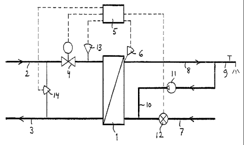
In Fig. 1, there is shown a heat exchanger 1, the primary side of which is
connected to a district central heating network with a forward line 2 and a
t o return line 3. In the forward line 2, there is a flow regulating valve 4,
which
is controlled by a regulator 5 in response to a signal from a temperature
sensor 6, which is disposed in the secondary circuit for hot tap-water of the
heat exchanger 1. This secondary circuit includes a feed line 7 for
consumption water and an outlet line 8 for heated consumption water, i.e.
1 s hot tap-water. This outlet line is assumed to be connected to a plurality
of
water taps in a building (only one such tap 9 is shown on the drawing). A
steady flow through the heat exchanger is maintained by means of a shunt
line 10 provided with a circulation pump 11.
CA 02249983 1998-09-24
WO 97/36138 PCT/SE97/00509
4
The system described so far is basically of a kind which is
previously known per se.
According to the invention atemperature sensor 6 is provided
in the outlet line 8 of the secondary circuit, preferably ;
adjacent to the heat exchanger 2, and is adapted to sense the
momentary temperature variations of the water in the outlet
line.
10Furthermore, a flow sensor 12 is provided in the secondary
circuit, preferably in the feed line 7, so as to measure the
relative flow fluctuations within a given, preset load range.
This flow sensor is also connected to the regulator 5 which is
adapted to control the flow regulating valve 4 in the primary
circuit already before the temperature in the outlet line 8 has
dropped or risen upon a sudden increase ar decrease of the flow
of hot tap-water. Hereby, the settling process can be conside-
rably attenuated, and the temperature of the hot tap-water can
be kept substantially constant or at least within narrow limits
20. even when the hot tap-water flow varies strongly.
Upon momentary load changes, being sensed by the flow sensor 12
and, with a certain delay, by the temperature sensor 6, the
flow regulating valve 4 will thus change its position, prima-
- rily in response to the size of the relative flow change but
also with a certain consideration to the thermodynamic pro-
perties of the overall system. This positional change of the
valve 4 is thus determined by an algorithm being adapted to the
particular system. The algorithm will calculate the size of the
- positional change on the basis of the change in energy demand
for the supplied non-heated consumption water with due account
taken of the dynamic properties of the system.
In systems with large variations of the temperature in the
_ forward line 2 and/or the pressure difference between the
forward line 2 and the return line 3, a temperature sensor 13
and/or a differential pressure sensor 14-may be disposed for an
automatic adaptation of the algorithm of the regulator.
CA 02249983 1998-09-24
WO 97/36138 PCT/SE97/00509
Measurements in residential buildings have shown that the
average consumption (for a period of 24 hours) of the hot tap-
water constitute about 20~ of the top level.- This top level
occurs during an accumulated relatively short time period of
5 about 5 minutes, the peaks being very short and the flow
variations thus being very strong. In spite of this fact, it is
possible to keep a temperature stability of ~2°C with the
control device of the present invention even if the system is
dimensioned on the basis of the accumulated or average consump- -
tion rather than the top consumption.
Therefore, the invention will enable a considerable saving of -
the investment cost of the system as well as an improved
temperature stability of the hot tap-water, thanks to the
simple structure and the quick response of the control device.
In principle, it is sufficient with only one flow sensor and
only one temperature sensor.
In Fig. 2, there is shown a simplified embodiment, where the
same reference numerals designate equivalent components as in
Fig. 1. The only difference is that the flow sensor 12, the
temperature sensor 13 and the differential pressure sensor 14
are connected to the temperature sensor 6', which will pass on
a corrected sensor signal to the regulator 5'. Upon an
increased flow, the temperature sensor will deliver a signal
corresponding to a lower temperature than the temperature being
sensed. Such an embodiment is especially suitable as a supple-
ment to existing systems in that only the sensors 12, 13, 14,
6', but not the regulator 5', has to be replaced (or supplemen-
ted) .
Those skilled in the art can carry out the invention in many
different ways within the scope of the appended claims. E.g.
the heat a<>changer may consist of a unit including two or more
heat exchangers connected in series and/or in parallel to each
other.
~~AA. 3 4, Y
.. _ : t~-~:'~ i v~~_~~''~.:~J:'''lv..'