Note: Descriptions are shown in the official language in which they were submitted.
CA 022~00~9 1998-09-2~
WO 97/37741 PCT/US97/05569
HIGH CAPACITY VAPOR-LIQUID CONTACT TRAY
B~ l~round of the InvPntion
This invention relates in general to mass transfer and exchange columns
and, more particularly, to vapor-liquid contact trays employed within such columns.
Vapor-liquid contact trays are used in mass transfer or exchange columns
to facilitate contact between upwardly flowing vapor streams and downwardly flowing
liquid streams. The trays are hol;Gonl~lly disposed within the columns to provide a
horizontal surface across which the liquid streams may flow. The trays are typically
formed from a solid sheet-like material and contain a plurality of apertures which allow
0 vapor to flow upwardly through the tray for interaction with liquid flowing across the top
surface of the tray. In trays known as sieve trays, the apcl lulcs are sized small enough
so that during operation of the colurnn the pressure of the vapor passing upwardly
through the apertures restricts or prevents liquid from passing downwardly through the
a~e. IUICS. In other types of trays, movable valves or stationary structural elements such
15 as bubble caps can be provided over the apertures to seal against the downward passage
of liquid.
Downcomers are used in combination with the vapor-liquid contact trays
described above to provide a passageway for liquid to pass downwardly from one tray
to an underlying tray. In single pass tray arrangements, the downcomers are provided at
2 o opposite ends of vertically adjacent trays so the liquid must flow completely across one
tray from the inlet end to the outlet end before it enters the downcomer for passage to the
next lower tray. The liquid then flows in the opposite direction across the lower tray and
enters the associated downcomer for passage to and across lower trays in the same back
and forth fashion. In double-pass tray arrangements, the tray is split into two streams
2 5 which travel in opposite directions on each tray. A center downcomer is provided on
every other tray and two end downcomers are placed at opposite ends of intermediate
trays to provide the double pass flow pattern.
A weir is also typically used at the outlet end of vapor-liquid contact trays
to cause liquid to accumulate on the top surface of the tray for enhanced interaction with
3 o the vapor bubbling upwardly through the apertures in the tray deck. The area of the tray
deck which contains the apertures in vapor-liquid contact trays is referred to as the
"active area" of the tray because the vapor-liquid interaction occurs above the tray in this
area. The active area typically does not include the area at the inlet end of the tray deck
CA 022~00~9 1998-09-2~
WO 97/37741 PCTtUS97/05569
which lies irnmediately below the outlet of the downcomer which is associated with the
overlying tray. This area of the tray below the downcomer outlet is referred to as the
downcomer receiving area and is typically a solid plate which receives the vertically
flowing discharge from the downcomer and redirects it horizontally to flow across the
tray.
One problem associated with conventional trays of the type described
above is the tendency for liquid to flow in a non-uniform manner across the tray.
Because the width of a circular tray increases in the direction of liquid flow from the inlet
end to the midpoint of the tray and then decreases from the midpoint to the outlet end, the
0 liquid tends to p.efe~ ially flow along the center portion of the tray. This often results
in decreased tray p~lroll"ance as liquid st~En~tes or forms non-uniform gradients along
the lateral edges or other portions of the tray. Previous attempts to reduce liquid
stagnation and non-uniform gradients have included the use of apertures which redirect
vapor from a vertical to horizontal flow path. The apertures thus cause liquid in the
vicinity of the apertures to flow in the direction of the redirected vapor. These apertures
are spaced about the tray and may be concentrated in those areas where liquid stagnation
or gradients tend to form. Regular sieve-type openings are used in combination with the
apertures, such as illustrated in U.S. Patent No. 3,417,975 to Williams et al. and U.S.
Patent No. 3,282,576 to Bruckert et al. While this combination of vapor redirecting
2 0 c~ ules and sieve-type openings can achieve the desired results, fabrication of the trays
is a time consuming process because separate machinery must be used to first form the
sieve-type openings and then the vapor redirecting ap~. IUI~S. A need has thus arisen for
an improved tray which may be more easily fabricated and reduces liquid stagnation and
undesirable gradients across and along the edges of the tray.
2 5 Another important consideration in the design of vapor-liquid contact
trays is the desire to increase the vapor handling capacity and thus the effectiveness of
the tray. In sieve trays, this is typically accomplished by increasing the number and/or
size of apertures to increase the open area on the trays. The performance of the tray,
however, may suffer at lower than design vapor flow rates as increased amounts of liquid
3 o pass or "weep" through the open areas. To overcome this problem, bubble caps or
pressure responsive valves can be provided over the openings to reduce the amount of
CA 022~00~9 1998-09-2~
WO 97t37741 PCT/US97/05569
liquid weeping through the openings at low vapor flow rates. Valves have the added
advantage of deflecting vapor from a vertical flow path to a horizontal flow path which
is believed to enhance tray performance. Because these valves significantly increase the
cost and mz~inten~nce required for the trays it is desirable at least in some applications to
5 utilize fixed deflectors over the open areas.
S~lnmary of the Invention
It is an object of this invention to provide a vapor-liquid contact tray with
fixed roof a~tl lul~S which cause directional vapor flow to facilitate liquid flow across the
tray so that liquid stagnation is less likely to occur and more uniform flow liquid flow is
0 achieved, including along the lateral edges of the tray.
It is another object of this invention to provide a vapor-liquid contact tray
with apertures having fixed roof structures which cause directional vapor flow to
facilitate the desired liquid flow across the tray and which are arrayed so that the fixed
roof structures shield against liquid entry into the apertures positioned ~ ,nt the liquid
15 receiving area of the tray.
It is a further object of this invention to provide a vapor-liquid contract
tray with a~u~l Lulcs having some of the described fixed roof structures oriented adjacent
the liquid receiving area of the tray so that the vapor is deflected in the direction of outlet
end of the tray to cause liquid to be pulled from the downcomer receiving area under the
2 o influence of the vacuum resulting from the deflected vapor, thereby facilitating more
rapid frothing of the liquid and more efficient mass transfer bt;lw~ll the liquid and vapor.
It is a still further object of this invention to provide a vapor-liquid contacttray with fixed roof ~llules to provide more uniforrn liquid flow across the tray and
which also permit increased vapor h~n(lling capacity to be achieved with acceptable
2 5 levels of liquid enlldi n,. .ent and weeping.
It is yet another object of this invention to provide vapor-liquid contact
trays which provide the desired uniform liquid flow and mass transfer efficiency using
only fixed roof apertures rather than combinations of such apertures and sieve-type
openings so that the tray can be more readily fabricated without the separate processing
3 o steps that would be required to form both fixed roof apertures and sieve-type openings.
CA 022~00~9 1998-09-2~
WO 97/37741 PCTtUS97/05569
To accomplish these and other related objects of the invention, a vapor-
liquid contact tray is provided for placement within a mass transfer column to facilitate
contact and interaction between ascending vapor and descending liquid. The tray
comprises: an at least partially planar plate having a liquid receiving area at an inlet end
5 for underlying a discharge end of an overlying downcomer and receiving liquid
therefrom; a downcomer positioned at an outlet end of the plate for removing liquid from
the plate and directing it to an underlying tray; a plurality of openings in said plate in an
active area outside of said liquid receiving area, said openings being sized to permit
upward passage of vapor for interaction with liquid flowing across said plate from the
0 inlet end to the outlet end, said openings being arrayed with a row of openings extending
along and ~dj~c~nt to said liquid receiving area; and fixed roof structures associated with
each of said openings, each of said fixed roof structures having a deflector which overlies
and is spaced above the associated opening for cont~rting vapor flowing vertically
upward through the associated opening and deflecting the vapor to one or more generally
5 horizontal flow paths, said fixed roof structures further col . ~p, ;~ g end plates which join
opposed ends of the deflector to the plate adjacent said associated opening, some of the
fixed roof structures associated with said openings in the first row of openings being
oriented to place the end plates facing the liquid receiving area to deflect liquid leaving
the liquid receiving area above and around the associated openings, substantially all of
2 o the rem~ining fixed roof structures associated with said openings in the first row of
openings having the deflectors joined to the plate along an edge closest to the liquid
receiving area to deflect liquid leaving the liquid receiving area above and around the
associated openings and to redirect substantially all of the vapor flowing upwardly from
the associated openings in a direction toward the outlet end of the plate to facilitate
2 5 frothing of the liquid by mixing with said vapor along said first row of openings.
In another aspect, the invention is directed to a method of operating the
tray to provide more uniform liquid flow and to increase the vapor h~n~lling capacity and
effectiveness of the tray.
CA 022~00~9 1998-09-2~
wo 97/37741 YCT/US97/05569
Brief Description of the Dr~ ;fi
In the accompanying drawings which form a part of the specification and
are to be read in conjunction therewith and in which like reference numerals are used to
indicate like parts in the various views:
Fig. 1 is a fragmentary perspective view of a mass transfer column
employing vapor-liquid contact trays constructed in accordance with the present
mventlon;
Fig. 2 is a top plan view of the column taken in horizontal section along
line 2-2 of Fig. 1 in the direction of the arrows and showing one of the vapor-liquid
contact trays;
Fig. 3 is an enlarged fr:~gment~ry top plan view of the vapor-liquid contact
tray taken within the area ~Içsignzltecl by the numeral 3 in Fig. 2;
Fig. 4 is an enlarged, fragmentary perspective view of one embodiment
of the fixed roof ~t;l ~ules formed in the vapor-liquid contact trays;
Fig. 5 is a side elevation view of the fixed roof aperture shown in Fig. 4
and taken along line 5-5 of Fig. 4 in the direction of the arrows;
Fig. 6 is an enlarged, fragmentary perspective view of a variation of the
fixed roof aperture in which the roof slopes from side to side;
Fig. 7 is a side elevation view of the fixed roof aperture shown in Fig. 6
2 o and taken along line 7-7 of Fig. 6 in the direction of the arrows;
Fig. 8 is an enlarged, fr~gment~ry perspective view of another variation
of the fixed roof aperture in which the roof slopes from one end to the other;
Fig. 9 is a side elevation view of the fixed roof aperture shown in Fig. 8
and taken along line 9-9 of Fig. 8 in the direction of the arrows;
Fig. l O is an enlarged perspective view of another embodiment of the
fixed roof apertures positioned in the vapor-liquid contact tray in the first row of
apertures at the inlet end of the tray;
Fig. 11 is an enlarged fragmentary top plan view of another embodiment
of the vapor-liquid contact tray employing the variations of the fixed roof apertures
shown in Figs. 6-10; and
CA 022~00~9 l998-09-2~
WO 97/37741 PCT/US97/05569
Fig. 12 is a graph comparing the vapor h~n(lling capacity of the vapor-
liquid contact tray of the present invention with conventional sieve trays.
Description of the Preferred Embodiments
Referring now to the drawings in greater detail, and initially to Fig. 1, a
5 mass transfer or heat exchange column is designated generally by the numeral 20 and
comprises a cylindrical external shell 22 which defines an open interior region 24 in
which a plurality of vapor-liquid contact trays 26 of the present invention are located.
Column 20 is of the type used for processing liquid and vapor streams,
including to obtain fractionation products. The column 20 is vertically elongated and
0 may be of any suitable configuration, including polygonal, instead of the cylindrical
shape which is illll~tr~te.l The dimensions of the column 20 may be selected as desired
for the int~n~lecl processing operations to be conducted therein. Likewise, the materials
selected for the ext~rn~l shell can be selected from various materials which are suitably
rigid and compatible with the processing operations.
Only a portion of column 20 is illustrated because the general structure of
these types of columns is well known to those of skill in the art. One or more liquid
streams can be directed to the column and one or more vapor streams can also be directed
to the column or generated within the column in a known manner. Int~rn~l~ such as beds
of packing may typically be located in areas above and/or below the illustrated portion
2 0 of the column co"~ g the trays 26 in order to carry out the desired processing of the
liquid and vapor streams. Other ~plopliate column components such as connections and
lines for feed, product removal and reflux streams, and reboilers, condensers and the like
are not illustrated because of their conventional nature.
The vapor-liquid contact trays 26 of the present invention are generally
25 horizontally disposed with the vertical spacing between adjacent trays being selected
based on known process parameters. Each tray 26 is generally planar and extends
completely across the horizontal cross section of the column 20. The trays 26 may be
formed from sheet material and will typically, but not necessarily, be constructed from
various metals which are compatible with the vapor and liquid processing occurring
3 o within the column 20. Suitable brackets (not shown) are used to support the trays on the
inner face of the column shell 22.
CA 022~00~9 1998-09-2~
WO 97/37741 PCT/US97/05569
Each tray 26 has an opening at an outlet end 28 which is located adjacent
a downcomer 30 which provides a passageway for liquid to flow downwardly from one
tray to an inlet end 29 of the next underlying tray. The downcomer 30 is formed by a
generally planar, vertically extending wall 32 which is connected at its opposed lateral
5 ends to the column shell 22 so that the wall 32 and shell 22 form a liquid confining
passage. It will, of course, be appreciated that additional walls can be provided instead
of using all or part of the shell 22 in the downcomer construction, such as when the
downcomer is located elsewhere on the tray. The downcomer wall 32 is joined to the
outlet end 28 of the tray 26 and extends downwardly to a position a preselected distance
1 o above the underlying tray 26.
The downcomers 30 are located at opposite ends of successive trays 26
so that liquid must flow completely across each tray in a back and forth manner as it
~lesc~n-l~ through the column 20. This type of flow pattern is referred to as a single pass
arrangement because a single liquid stream flows across each tray 26 from the inlet end
1 5 29 to outlet end 28. It will be appreciated that the principles of the present invention are
also applicable to double pass and other multiple pass trays in which two are more
downcomers are positioned on each tray 26 and the single liquid stream is split into two
or more strearns.
Each tray 26 also includes an optional weir 34 which extends upwardly
2 o above the tray 26 to cause liquid to accumulate to a preselected depth on the tray before
it spills over the weir and enters the downcomer 30. The weir 34 is typically formed as
a vertical extension of downcomer wall 32, but it can be a separate component if desired.
The weir 34 is typically of a height such that it termin~tes at a level above the lower
discharge end of the downcomer 30 associated with the overlying tray 26. This causes
2 5 the discharge end of the downcomer to be submerged below the liquid level on the tray
to seal against vapor flowing upwardly into the downcomer 30.
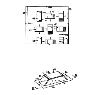
Turning now additionally to Fig. 2, each tray 26 preferably includes a
generally imperforate liquid receiving area 36 at its inlet end 29. The liquid receiving
area 36 is generally planar and is sized to substantially completely underlie the lower
3 o discharge end of the overlying downcomer 30. The liquid receiving area 36 serves to
deflect the downward mom~.nhlm of the discharged liquid and redirect it across the tray
CA 022~00~9 1998-09-2~
WO 97/37741 PCT/US97/05569
26 in the direction of the outlet end 28. Although the liquid receiving area 36 is generally
imperforate, directional louvres or other perforate structures of the type disclosed in U.S .
Patent No. 5,480,595, which is incorporated herein by reference in its entirety, may be
included in the liquid receiving area if desired.
Turning additionally to Figs. 3-5, each tray 26 includes a plurality of
generally uniforrnly spaced openings 38 which extend completely through the tray 26 in
a region between the liquid receiving area 36 and the downcomer 30 which removesliquid from the kay. The openings 38 are rectangular in shape, but could be other
configurations if desired, and serve to allow vapor to pass upwardly through the tray 26
o for interaction with liquid flowing across the top surface of the tray. The region of the
kay co~ g these openings 38 is known as an "active area" 40 because of the vapor-
liquid interaction which occurs thereon.
Each opening 38 is covered by one of various types of fixed roof
structures. One type of fixed roof skucture 42 is illuskated in Figs. 4 and 5 and
comprises a planar and generally rectangular deflector 44 which is spaced above the
opening 38 and is generally planar with the tray 26. The fixed roof structures 42 also
include inclined planar and rectangular end plates 46 which join the opposed ends of the
deflector 44 to the kay 26. The end plates 46 not only serve to attach the deflector 44 to
the kay, but also close the ends of the long axis of the rectangular opening 38. Vapor
flowing upwardly through the opening 38 is thus divided into two generally equalportions and forced to flow in opposite hofl~on~l directions along the short axis of the
opening after being deflected by the deflector 44 of the fixed roof skucture 42. The end
plates 46 further serve to shield the opening from liquid which is flowing in the direction
ofthe long axis of opening 38. Where needed, the end plates 46 deflect liquid around and
2 5 upwardly away from the opening 38 to reduce the opportunity for the momentum of the
liquid to cause the liquid to enter the opening by overcoming the upward pressure exerted
by the vapor flowing through the opening. It will be appreciated that the deflector 44 and
inclined end plates 46 may be formed from those portions of the tray 26 which are
removed to form the associated opening 38, such as using techniques known to those of
3 o skill in the art. The deflector 44 may also be formed into other shapes, including a
square, trapezoid, ellipse, diamond or circle.
CA 022~00~9 1998-09-2~
WO 97/37741 PCT/US97/05569
The fixed roof structures 42 can be varied in a number of respects and still
accomplish the desired objectives of causing deflection of the vapor passing through
openings 38 and shielding the openings 38 against entry of liquid. For example, the
deflector 44 and end plates 46 can be forrned as an arched structure. Alternatively, as
5 shown in Figs. 6 and 7, the deflector 44 and end plates 46 can be formed as trapezoids
which are tilted in one direction to cause the vapor to be split in two unequal portions
with a greater amount of vapor being pl efe~ Lially funneled in one direction along the
short axis ofthe rectangular opening 38. In a still further embodiment as shown in Figs.
8 and 9, the deflector 44 and end plates 46 can be of rectangular construction, but with
10 one of the end plates 46 being shorter than the other to cause the deflector to 44 to be
angled upwardly along the long axis of the opening 38. In this embodiment, the vapor
stream is still split into two generally equal portions but are directed at an angle between
the short and long axes of the opening 38. It can thus be appreciated that the inclination
of the deflector 44 and end plates 46 can be varied to cause preferential flow of vapor in
15 one direction or to vary the angle of flow of generally equal portions of vapor.
The openings 38 are typically arrayed in a pattern with their long
dimension ç~tPn-ling either parallel or perpendicular to the direction of liquid flow across
the tray 26, although in some applications the long dimension may extend at an angle
between the parallel and perpendicular directions. Likewise, the long dimension of the
2 o deflector 44 will typically, but not necessarily always, extend in the same general
direction as the long ~lim~n~ion of the associated opening. In one preferred array, the
openings are placed in a plurality of generally evenly spaced rows which extend
perpendicular to the direction of liquid flow. The openings 38 in successive rows are
aligned in columns in a direction parallel to the liquid flow to form a generally square
2 5 grid of openings 38 distributed across the active area 40 of the tray 26. The direction of
the long ~im~on.~ion of ~dj~ççnt openings 38 and associated deflectors 44 in each row and
column alternates from parallel to perpendicular in relation to the direction of liquid flow.
This array of openings and deflectors extending in altçrn~ting directions allows vapor
passing upwardly through each opening 38 to be redirected by the fixed roof structure 42
3 o in directions where they will encounter the inclined end plates 46 of adjacent roof
structures rather than the generally vertical discharge openings formed by the roof
CA 022~00~9 1998-09-2~
WO 97/37741 PCT/US97/05569
- 10-
structures. In this manner, the fixed roof structures aid in the desired frothing and vapor-
liquid interaction by redirecting the vertically flowing vapor to predetermined generally
horizontal flow paths. By orienting the vapor discharge paths in the described marmer,
the momentum of the vapor is more efficiently transferred to the liquid and facilitates
5 more uniform spreading and mixing of the liquid across the entire active area 40 of the
tray 26. Other arrays of openings 38 and deflectors 44 are also possible. For example,
adjacent rows of openings and deflectors can be offset to form a triangular pattern with
openings in every other row being in alignment. In addition, the openings 38 and/or
deflectors can all extend in the same general direction, such as parallel to the direction
o of liquid flow.
It has been detçrmined that at least the first row of openings 38 along and
adjacent the liquid receiving area 36 should be shielded from liquid exiting the liquid
receiving area 36 because the relatively high velocity, density and momentum of the
liquid may force the liquid into the openings where it would then weep through the tray.
5 This shielding of some of the openings is accomplished by orienting the openings with
their long axis ex1~n.1in~ in the direction of the outlet end 28 of the tray 26 so that the end
plates 46 and deflectors 44 of the associated fixed roof structures are oriented to redirect
the flow of liquid around and above the openings 38. Vapor exits these openings and
roof structures in a lateral directions which are generally perpendicular to the direction
2 o of liquid flow as it exits the liquid receiving area 36, thereby further controlling liquid
movement and facilitating frothing of the liquid.
In accordance with the present invention, it has unexpectedly been
discovered that tray performance can be measurably increased by placement of louvre-
type fixed roof structures 48 in association with some of the openings 38 in the first row
25 of openings. The louvre-type fixed roof structures 48 are shown in Fig. l0 and are
similar to structures 42 except the deflectors 44 are joined to the tray along an upstream
edge so that all of the vapor exits along the discharge opening formed at the opposite or
dow,lsl,eanl edge of the deflectors. The structures 48 preferably include end plates 46
which join the ends of the deflectors 44 to the tray, but the end plates could be omitted
3 o in certain applications. As illustrated in Fig. 3, the louvre-type fixed roof structures can
be used in an alternating fashion with the fixed roof structures 42 oriented as described
CA 022~00~9 1998-09-2~
WO 97/37741 PCT/US97/05569
above in the first row of openings 38. Other patterns are, of course, possible and may be
plcrt;~l~;d in certain applications. The openings 38 associated with the louvre-type fixed
roof structures will typically be oriented so that the short dimension of the openings
extend in the direction of the outlet end 28 of the tray 26. This orientation places the long
5 dimension of the opening generally perpendicular to the direction of liquid flow so that
vapor discharged from the openings is spread along a greater portion of the liquid exiting
the liquid receiving area. It has been deterrnined that the use of these louvre-type fixed
roof structures 48 in combination with the structures 42 shields against liquid entering
the associated openings 38 in the first row of openings, but also contributes to more rapid
0 frothing of the liquid and thereby reduces the amount of liquid weeping through
successive rows of openings on the tray.
It will be appreciated that the directional fixed roof structures 42a and 42b
illustrated in Figs. 6-9 can be used in place of or in combination with the fixed roof
structures 42 illustrated in Figs. 4-5. An example of this is shown in Fig. 11 where the
1 5 openings in the second and successive rows of openings 38 are shielded by the directional
fixed roof structures 42a and 42b. As illustrated sch.?n~tically by the arrows in Fig. 11,
these fixed roof structures 42a and 42b cause a greater amount of vapor to be discharged
in the downstream direction in comparison to the upstream direction. The directional
structures 42a and 42b thus tend to ~l~fe~ Lially direct vapor and liquid in the2 o downstream direction toward the outlet end 28 of the tray 26. In other embodiments such
as illustrated in Fig. 2, the directional fixed roof structures 42a and 42b can be
concentrated in those regions of the tray where liquid st~gn~tion or gradients tend to
occur, such as in and ~ C~nt to lateral regions 40a of active area 40. The structures 42a
and 42b are oriented to preferentially direct the vapor and liquid strearns into and then
2 5 through the lateral regions 40a as illustrated schematically by the arrows in Fig. 2. The
other fixed roof structures 42 which divide the vapor stream into roughly equal oppositely
directed portions can be concentrated in a central region 40b of active area 40 where
liquid stagnation and gradients may be of less concern. In applications where liquid
stagnation or gradients tend not to be of concern, such as in connection with relatively
3 o smaller diameter trays, the fixed roof structures 42 could be used throughout the entire
active area rather than in combination with structures 42a and 42b. It will also be
CA 022~00~9 1998-09-2~
WO 97/37741 PCT/USg7/05569
- 12-
appreciated that more fixed roof structures can be located in particular regions of the tray
than in other regions. For instance, the structures can be concentrated in the lateral
portions 40a of the active area 40 with fewer structures being placed in the center portion
of the active area 40. In still another variation, the long dimension of each of the
openings 38 can extend in the general direction of liquid flow with directional fixed roof
structures 42a and 42b being used to direct vapor and thus liquid through lateral portions
40a or other problem areas of the tray 26.
Turning now to Fig. 12~ it can be seen that markedly improved tray
performance can be achieved by lltili7.ing the fixed roof structures 42 and 48 as described
above. The tray 26 constructed in accordance with the present invention and having a
total of 18.4% open area when measured in the vertical plane at the downstream edge of
the structures 42 and 48 and 13.2% when measured in the horizontal plane of the
associated openings 38 was tested against sieve trays having varying hole diameters and
total open area. The tray 26 had a higher relative liquid and vapor capacity based on a
10% liquid e~ a;.~ ent rate when colllpaled against each of the sieve trays, including
those having a much higher amount of open area.
From the foregoing, it will be seen that this invention is one well adapted
to attain all the ends and objects hereinabove set forth together with other advantages
which are inherent to the structure.
2 o It will be understood that certain features and subcombinations are of
utility and may be employed without reference to other features and subcombinations.
This is contemplated by and is within the scope of the claims.
Since many possible embo~lim~nts may be made of the invention without
departing from the scope thereof, it is to be understood that all matter herein set forth or
2 5 shown in the accompanying drawings is to be i~ led as illustrative and not in a
limiting sense.