Note: Descriptions are shown in the official language in which they were submitted.
CA 02250071 1998-09-22
WO 97/3916g PCT/US97/06106
PROCESS FOR MAKING MICROPOROUS FIBERS
Field of the l~ention
The p,esenl invention relates to the manufacture of synthetic fibers. More particularly,
the invention relates to a mJU~od and app~(atus for making synthetic fibers which are
5 porous and exhibit i,npro~d ",echan:cal prupe.lies.
Back~round of the Invontion
Porous films have been made by i..co"uûrating filler particles into a poly."er material and
10 stretching the material to form a nlm havin~ voids induced. Such techniques, ho.~ over,
have not been adequate for forming small ulid",eler porous fibers beca~se the resultant
fibers have been e~cess;vely large or have inadequate l"echan ~~' propert;es, such as
IOW sbeillJtll and low tou~hness.
15 Porous fibers have been made by employing convenliorial phase separation n,ell,Gds.
Such IllelhGJs generally involve mixing a polyl"er resin with a diluent or a pl~ er,
quenching ~he poly.,.er solution in a liquid medium to induce phase separdtion, and
washing away the diluent to leave behind an il,ter.;or)nected porous stnucture. Other
techniques have employed a blowing agent or a swelling agent to create a mic~porous
20 structure. Still other techniques have employed an env;.onmclltal crazing to prt,pa,t5
porous ll.alQ.ials.
Convenl;onal techniques, ho/:_vor, such as those desc,ibed above, have not been able
to produce porous fibers at suffciently high speeds In add;tion, the techn-~ues have not
CA 02250071 1998-09-22
W O 97139169 PCT~US97/06106
~de~uately produced porous fibers havin~ desired comb nations of small cli~",eter, high
wettability, high pe.."6ability to liquid, high ~'ongdlion and high tensile sl,er.gU,.
Brief Des~i"tion of the Invention
Generally stated, the pn.sent invention provides a distincUve ~o~hn ~, e for making
porous fiber. The technique includes a stretchin9 of a subsbntially conUnuous fiber while
the fiber is in an ope,~t;~e associaUon with an erfecti~ quanUty of surfac~active
."ale,ial. The fiber can be produced from a source material which indudes a
10 ll.e,.nopt~tic, Grienlable material, and can include at least about 0.35 weight per~ent
(wt%) of a supplemental material. In parUcular a ~pe~ of the invention, the fiber may be
conta~ted with a first quantity of surfac~active fluid. In other Asp6~ ., the fiber may be
contacted with a first quanUty of surfac~ac,tive fluid and at least a separate, second
quantity of surfac~active fluid. In still other ;~pe~ , the fiber may be subjected to a
1~ s~l~cted plurality stretching operations.
In its various ~5pi;C~ the technique of the invention can ~he.,LJaly and effidently
produce porous fibers at high speed. In parlicular A5pe~, the technique can produce
fibers havin~ desired combinations of small size, high wettability, high wabr-Acc~ssibility,
20 high tensile abe~ UI, hi~h elongation to break and irnprol~d ability to be further
prucessed to form nonwoven fabrics and other artides of manufacture.
Brief Des~i"tion of the Drawinas
25 The ,c .~s~nl invention will be more fully under~lood and further advu"tages will beco.,.e
appar~nl when .~fer..nce is made to the followed debiled desc~iption of the invention
and the d~uv.ings, in whidh:
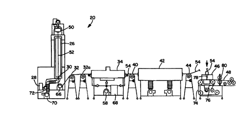
Fi~. 1 shows a ,epn~~entative sche-,-alic view of the n-et;.od and apparatus provided by
30 the presenl invenUon;
Fi~. 2 shows a s~;l.e,.-atic view of repn~senbtiiQ fiber-forming, quenching and draw-down
a5pe,,1C of the invenUon;
CA 02250071 1998-09-22
WO 97/39169 PCT/US97/06106
Fig. 3 shov~s a ~r ~sentdlive technique for subjecting the polymer fiber to a liquid bath
of surface-active fluid;
Fig. 4 shows a repr~sentative web former fot further pr~ cessing the porous hber of the
5 invention to ~Jener~te a desired fibrous web.
Detailed Derc~Jtion of the Invention
With .~fer~nce to Figs. 1 and 2, a ,..etl ~od and apparat.Js for maWng a porous fiber 54
10 provldes for a stretchin~J of a substantially continuous fiber 52 while the hber 52 is in an
operati~e AcsO~ tion with an effedve quantity of surface active material. The fiber 52 is
produced from a source material 56 which incriudes a thellllGplastic., onenlable ",dtefial
and can include at least about 0.35 weight pa,~,ant (wt%) of a supplemenbl material,
such as a filler mabrial. The surfa~active material may be opaldti~Gly associated by
15 incG",orating the surfac~active material in the source mabrial prior to fiber forming, or
by a sapa.Jt~, conta-,tin~ of the surface a_LJe liquid onto already formed hber. The
stretching may be a~,-lplished by any conven~onal stretchin~ i"c~,l-an;s,~" such as
aerodynamic stretching, a sysbm of draw rolls or the like, as well as combinations
thereof. In the ~pr~se.qlatively shown configuration, for sxample, the stretching can bs
20 pe, fo,~nad by a sysbm which includ~ a dra~down roll ~. The stretching and dl~ing
system can also include additional drawing ~..ecl.an;s..,s, such as a system of draw rolls
32 and 32a, and/or draw rollsr 40. In particular a~pe-,~C of ths invention, the hber may be
subjscted to a selected plurality stretchin~ operdlions.
25 A particular aspect of ~e t~chn ,ue of the invention can p~ida for a formation-
stretchin~ of a substanffally continuous fiber 52 while the fiber 52 is in an oparably
erfb~,ti;o contact wi~ a f.,...,aUon-quantity of surface-active fluid, such as a surface
active iiquid 38. The fiber 52 is produced from a source material 56 which includes a
polymer mabrial and at least about 0.35 wei~ht per~nl (wt%) of a supplemental
30 material. The fiber 52 has been pretreated with a first quanffty of surfac~acffve fluid,
such as surface-acffve liquid 28, and has been inc~",entally ~tretched.
In the illustrated a.,~n~e",6,lt, the ", ~thod and appa-dtus for making the porous fiber 54
includes a reservoir, such as hopper 22, which holds and delivers constituent con~ponen~
35 materials desired for producin~ the se'elcted source material 56. The source ...atar,al
CA 02250071 1998-09-22
W O 97/39169 PCTAUS97/06106
includes a U~ ,-oplasUc, G-ienlable material and at least about 0.35 wt% of a
s~rF'smantal ~--alorial, where the weight peroentdge is determined with .aspa~t to a total
weight of the overall source Illateridl. A formin~ r,lechanisll-, such as provided by an
extruder 24 and a fiber former 50, s~ P ' ~ S subslantially continuous fiber 52. The fiber
5 52 is pretreated with a first quantity of surface-active fluid, such as a first surface-active
liquid 28. A first stretching .ll6ct)anism, such as provided by a system which includes
draw rolls 32 and 32a, inc~---antally stn,td~es the pretreated fiber 52. The fiber 52 is
placed in an op,e~bly effecUve contact with a second quantity of surface-active fluid,
such as a surface-active fluid 36. A second stretchin~ mecl)an;sm, such as pr~ided by
10 a second system which includes draw roller 40, fo-",ation-stretches the fiber 52 while the
fiber is in the op~rdbl~ eff~.t;~c contact with the second quanUty of surface-acUve fluid.
vVhen produdn~ porous polymar films, such as mi~pon~us poly.--er films, known
convanti~nal techniques have stretched films cG~ 05ed of precursor materials which
15 have contained up to 65 wt% of filler materials. In the production of porous fibers, it has
been difficu!t to form fibers while in~.~G.ating desired, el.e_L1~- amounts of filler
materials, and it has been particularly difficult to produce hbers having a denier per fiber
of less than about 50 denier under such conditions. Conventional fiber forming
pn~cl3sses such as those which employ stretching to generab pores, have typically been
20 limited to inc4l~G~J~n~ less than 0.5 wtg~ of the desired filler ,.,ate.ial.
In the pn7s6nl invention, the source material 56 includes a U.em.opl~~tir., o,ientable
..,alenals, such as U.ell-,opl~stic and orie"table poly.--e.a, copoly.---,r~, blends, mixtures,
compounds and other combinations thereof. Dasir~bly, the U .a.n.Gpl ~stic ."atenals do
25 not indude highly reac~ve groups.
In particular a,.dn~6...ents of the invention, the source mabrial 56 can be a polyolefinic
..-aterial. For example, the source material may indude l,G.-.opolymers of polyethylene
or poly~,rupylene, or may indude copoly.n.,.a of ethylene and poly"n~pylene. In other
30 a"d,)g~menls, the source ...a~arial may indude another poly...ar material, sudh 8S a
polyeU ,er, a copolyether, a polyamid, 8 copolyamid, a polyester or a copûlysster, as well
as copolymers, blends, mixtures and other comb nations thereof.
The U,6""Gplastic material is melt pn~cesslble, and in particulamqspec~ of the invention,
35 the ",ateiial can have a melt flow rab (MFR) value of not less than about 1 ~/10 minutes
CA 02250071 1998-09-22
W O 97/39169 PCT~US97/06106
(based on ASTM D1238-L). . Alblllat;1~ely, the MFR value can be not less than about
109/10 minutes, and optionally, can be not less than about 20 9/10 minutes. In other
acre~ of the i,.~enbon, the MFR value can be not more than 200 9/10 minutes.
AlternaUvely, the MFR value can be not more than about 1009/10 minutes, and
5 optionally, can be not more than about 40 9/10 minutes to provide desired levels of
processibility.
Such melt p,ucasstlJle, UlellllGplastic mabrial can, for example, be provided by a
hGmopol~mer poly"r.~len~. C~,r.-mo.~ially available polyolefins, sudh as Himont PF
301, PF 304, and PF 305, E~aon PP 3445, Shell l~oly.,ler E5D47, are also r~p,_rentat;~o
of suitable mabrials. SUII other suitable mabrials indude, for example, i_ndGm
cOpoly~ .a, sudh as a landon~ copoly."er containing propylene and eU~lene (e.g. Exxon
9355 containing 3.5 % oU.yl~ne), and hG--,opolym~.a, sudl as hG."opoly ner
polyethylene, which have MFR values similar to those ",entioned herein. The poly."er
15 resins may conbin small amounts (e.~. about 0.05 to 5 parts of additive to 100 parts of
resin) of pr~assing additives, such as calcium ster,ate or other acid scavGn~a,a. Other
additives can indude, for example, silicon glycol copoly...e, a, Gr~&nosilicone compounds,
olefinic elasto."ers, and low ...~'e~ wei~ht pa,~fins or other lul)lic~ti.l~ additives.
Various pi~ment additives may also be i"~"~orated. For example, pigment conce"t,dtes
20 such as a tibnium dioxide pigment conc~nt,dte with low ,-.ole~ ~'ar weight polyethylene
pl1sti~ ;~ar can be employed as a pr~c e s~ ng additive. The various additives can have a
plasticizing effect, can i..,pro~a the strength and so~b.ess of the fiber, and can help
facilibte one or more of the extrusion, fiber spinning, and stretching p,ucasses
25 The source mabrial 5~ can also indude a further supplemental material, and the
supplementai material may include a filler mabrial, and/or a su, It,.,lant or other surface-
active material. The filler material can be a particulab material which can help provide
porosity-initiating, debonding sibs to onhance the desired fo""ation of pores during the
various stretching opeld~GIls applied to the fiber 52. The filler ",aterial can help provide
30 a desired surface-modified fiber, and can help ~nha,1ce a desired "sliding effect"
generdted during s~hse~uent stretching operdlions. In addition, the filler ",al~,ial help
preserve the pores that are gener~ted during the various stretching operc,lions.
Where the supplemental material includes a surfac~active mabrial, such as a s-"fdc~anl
35 or other material having a low surface energy (e.g. silicone oil), the surface active
CA 02250071 1998-09-22
W O 97/39169 PCT~US97/06106
".aterial can help reduce the surface energy of the fiber as well as provide lubricaliGn
amon~ the polymer se~"-ents which form the fiber 52. The reduced surface energy and
lubncation can help create the "sliding effect" during the suhsequent stretchingoperations.
s
The supplemental filler material can be or~an c or i,-or~an:~ and the filler material is
desi(dbly in the form of individual, discrete particles. The fillers may be subjected to a
surface b~ab"enl with various coatin9s and su,h~,la"S to impart an affinity to the
polymer resin in the ~ource mabrial, to reduce a~lol"er~Lon, to improve filler
10 ~ispe,aion, and to pr~ida a controlled intor~ction with fluids, such as body fluids, blood
or water. Examples of an inor,ual~-c filler can inciude metal oxides, as well as hyd~ides,
carbonates and sulfates of mebls. Other suibble inor~anic filler materials can inciude,
for example, calcium carbonate, various kinds of clay, silica, alumina, barium sulfab,
sodium carbonate, blc""a~nesium carbonate"-,&~nesium suffate, banum ca,LGnab,
15 kaolin, mica, carbon, calcium oxide, Ill&,tll~S"'Il oxide, aluminum hycll~,~ide, titanium
dioxide, powdered metals, gla~s mic uspho.~,~, or vugular voi~containing particies. Still
other inor~an;c fillers can inciude those with particles havin~ higher aspect raUos, such
as talc, mica, and woilastonib, but such fillers may be less effective. Repmre,lldtive
o~an-~ fillers can include, for example, pulp powders, wood pswde~s, cellulose
20 derivatives, chitin, chito~an powder, powdors of hi~hly crystalline, hi~h meltin~ polymers,
beads of highly crosslinked poly.,.a.a, powders of o.~anosilicones, and the like; as well
as comb-nations and derivaUves thereof.
In particular ~spe~, of the invention, tne fillers can have an avera~e particle size which
25 is not more than about 10 microns (ILm). Alt~--,ati~/ely, the average parUde size can be
not more than about 5 ~m, and opUonally, can be not more than about 1 ~m to provide
ill~pN~/~d pr~ssibility. In other ~pe~ of tne invention, the top cut partide size is not
moro than about 25 ~n. Altemaffvely, and the top cut partide size can be not more than
about 10 ~m, and opUonally can be not more than about 4 ~lm to provide improved
30 pr~cess~l ility durin~ the formation of fibers havin~ the desired size and porous
structure. The fillers may also be surface-mGJified by the incolporation of su(~a~lants,
and /or other materials, such as stearic or behe~ acid, which can be employed toimprove the prucessibility of the source mate. ial.
CA 02250071 1998-09-22
WO 97/39169 PCT/US97/06106
Examples of suitable filler materials include one or more of the f~IID~
(1) Dupont R-101 TiO2, which is available from E.l. OuPont de Nemours, and can
be s~qp'.sd in a concentrate form by Stand~ich Color Col~JGIatiGl-, a business havin~
offices located in Sodal Circle, Geor~ia 30279. This ",dtelial can provide ~ood
5 p~ocessibility.
(2) ri",-,enl Blue 15:1(10 % copper), which is distributed by St~nd~idge Color
CGI ~JordliGn. Fibers produced with this material may break more often.
(3) OMYACARB ~ UF CaCO3, which is available from OMYA, Inc., a business
havin~ offices located in Proctor, Vermont 05765. This ",atenal can have a top cut
10 particle size of about 4 ~m and a avard~e particle size of about 0.7~m, and can provide
good prw~ssilJility. This filler can be coated with a s~"h..~nl, such as Dow Coming 193
su, raclanl, before the compounding or other combinin~ v~/ith the source ",ate, ial 56. The
filler can also be coabd with other appn,pnate su, r~lant~, such as those "~cntioned
elsa~.er~ in the ~ nl de-r~i~tion.
(4) OMYACARB ~ UFT CaCO3 coated with stearic acid, which is available from
OMYA, Inc. This material can have a top cut partide size of about 4 ,um and a mean
particle size of about 0.7,um, and can provide ~ood p~ si~ility.
(5) SUPERCOAT~ CaCO3which is available from ECC Intemational, a business
having offices located in Atlanta, Geor~ia 30342, 5775 Peachtre~Dunwoody Road. This
20 "~atenal can have a top cut particle size of about 8 ~m and a mean particle size of
about 1 ~m. Fibers produced with this material may break more often.
(B) Powdered polydimethyl silsesquioxane (#22 or #23 Dow Comin~ AddiUve),
which is available from Dow Comin~, a business havin~ offices locabd in Midland,Michigan 48628 0997. This material can provide good pr~cessil~ility, while some
25 a~glomeraUons may be observed.
The supplemental mabrial can opUonally include a surfac~acUve material, such as a
surfactant or other mabrial havin~ a low surface ener~y (e.~. silicone oil). In parUcular
~spe~ of the invontion, the su,r~1anl, or other surfac~acUve material, can have a
30 Hydrophile-Lipophile Bdlance (HLB) number which is not more than about 18.
Alle",ati~ely, the HLB number is not more than about 1B, and opUonally is not more than
about 15. In other :~5p6.,1~ of the invenUon, the HLB number is not less than about 6.
- Altematively, the HLB number is not less than about 7, and optionally the HLB number is
not less than about 12. When the HLB number is too low, there can be insufficient
35 wettability. When the HLB number is too hi~h, the s~"ra~lanl may have insufficient
CA 02250071 1998-09-22
WO 97/39169 PCT/US97/06106
a~ esion to the poly.,.ar matrix of the source mabrial, and may be too easily washed
away during use. The HLB numbers of cGIllnle~ally available sulra~ldnt . can be found
in McCUTCHEON's Vol 2: Functional Materials, 1995.
5 A S~ su,r~-.lant can include silicon glycal copoly."ars, ca,~o~ ed alcohol
ethoxylates, various ethoxylabd alcohols, ethoA~lat~d alkyl phanols, eU-o~l,,t_d fatty
esters and the like, as well as comb-nations thereof.
Other suitable su.~acbnl~ can, for example, include one or more of the f~ ing:
(1) su.ra-,tants comp~sed of ethoxylated alkyl phel)oli, such as IGEPAL RC-620,
RC~30, CA- 620, 630, 720, C~530, ~10, ~30, 660, 710 and 730, which are availablefrom Rhone-Poulenc, a business having offices located in Cranbury, New Jersey.
(2) su.rd~lants ~l~posed of silicone glycol copoly.ll6,a, such as Da.~v Comino
D190, D193, FF400, and D1315, which are available from Dow Coming, a business
having omces located in Midland, Michigan.
(3) SU. rdc.lants cG~ o~d of et~hoxylated mono- and diglycerides, such as M~el 80
MGK, Masil SF 19, and M~el 1~5C, which are available from PPG Industries, a
business having offices located in Gumee, lL 60031.
(4) su.~a~.lanls cGmposed of etho,tyl~ted alcohols, such as Genapol 2~L-98N,
Genapol 2~L~ON, and Genapol 2~L-5, which are available from I loecl)sl Celanese
Corp., a business having omces located in Cl-a-lutt~, NC 28217.
(5) su. racla.~ts cGmposlsd of c~oAileted alcahol etnoxylates, such as Marlowet
4700 and Marlowet 4703, which are available from Huls America Inc., a business havin~
offices located in Piscata~Ney, NJ 08854.
(6) .,U-o~ '~ fatty esters, such as ratio,-ic 138C, rdtionic 122A, and ration
SSL, which are available from R.l.T.A. Corp., a business having offices located in
WoGdst~ , IL 60098.
The source ...itenal 5B incJudes not less than about 0.35 wt% of the supplemental
30 ."dt~nal, where the wei~ht pa.~el-ta~a is debrmined with ~~spe-,l to the total weight of
the cG."'~.ned source ,.,atenal. In particular Aspe~ of the invention, the amount of
supplemental ma- ~ hial is not less than about 0.5 wt%, and may desirably be st least
about 1 wt%. Alla.-ld~ ly, the amount of supplemental material is not less than about 5
wt%, and optionally is not less than about 10 wt%. In other Aspc~t~, of the invention, the
35 amount of supplemental material can up to about 50 wt% or more. The amount of
CA 02250071 1998-09-22
WO 97/39169 PCT/US97/06106
supplemenbl matorial is desirably not more than about 30 wt%. Alte...~ ely, the
amount of supplemenbl .,late,ial can be not more than about 20 wt% and optionally can
be not more than about 15 wt%.
5 In particular ~-~pa~ of the invention, the source material 56 can indude not less than
about 0.35 wt% of the filler material. In particular ~pe~ of the invention, the amount of
filler ~--at~rial is not less than about 0.5 wt%. Altematively, the amount of filler mal6ridl is
not less than about 1 wt%, and optionally is not less than about 5 wt%. In other ~ ~pech
of the invention, the amount of filler material can up to about 50 wt% or more. The
10 amount of filler material may desirably be not more than about 30 wt%. Altematively, the
amount of filler material can be not more than about 20 wt% and opffonally can be not
more than about 10 wt%.
In further ~pe~ of the il.~onlion where the supplemental mabfial includes a surfac~
15 active material, the amount of surface~active material, such as Slll f~n~, is at least
about 0.1 wt%. Altematively, the amount of surface-active material is at least about
1 wt%, and optionally, is at least about 3 wt%. In other nsp~-~ of the invention, the
amount of surfac~active material is not more than about 20 wt%. Albmatively, theamount of surfac~active material is not more than about 15 wt%, and opffonally, is not
20 more than about 10 wt%.
The selected source mabrial is operdbly b zlnSpGI led or otherwise delivered to a
".e~)anis... which converts the source mabrial 5~ into one or more individual strands or
fild,..ent~ of subsbntially continuous fiber 52. In the ~e,pr~sonlati~ely shown
25 configuration, the selecbd con.pononl mabrials are delivered to the extruder 24 which
further plvC~55eS the cG.,-~on~ l materials to form the desired fiber-forrning ,.,ate.ial.
The c~ ponen~ mabrials are suibbly melted and intell,~.Aad, and the resultant material
is extruded throu~h a suitable fiber former 50 to gener~la a sin~le fiber or a se'3~ed
plurali~y of individual, fiber filalllel ,ts or strands.
The co" ,ponent materials employed to fomm the source material for the fiber may be
suitably inte., llixed or oU n~ i5e combined at various localions alon~ the IlleU IGd and
appar~tus. For example, the con,ponent polymer materisls and supplemental ",dlenals
may be combined at a mixer prior to melUn~. Altematively, the cG",ponents may be35 combined in a mixer after meltin~, and opUonally, may be combined v~ithin the
CA 02250071 1998-09-22
W O 97/39169 PCTrUS97/06106
extruder 24. In addiUon a combination of such mixin~ techniques may be employed.Desirably, the componenls are combined in a sin~le screw or twin-screw extruder, and
the extruder can further include a static mixer to provide improved pNC'~;S efficiency due
to improved d;speraiol of the filler and su, ~l~nt materials, and due to reduced5 agglomerations in the extruded ",dte,ial.
An example of a suitable extruder is an extruder with a screw ~Jia",eler of 19 mm, and a
length/Jia-"GtGr (UD) raUo of about 24/1. Such an extruder is available from Alex James
8 Associates, Inc., a business havin~ offices in Greenville, South Carolina. Wlth
,ef6-~nca to Fig. 2, the extruder 24 can include a conventional, on-line staUc mixer 62.
Suitable static mixers are available from Koeh En~ineering Co",pan~" Inc., a business
having offices located in Wichita, Kansas.
From the extruder24, the extrudates are delivered by a conve"tiGnal Illetelill~ pump ~4
15 to the fiber fommer 50. Various types of conventional fiber fomning ",echan.sms may be
employed. A suibble fiber fomler can, for example, be ~ ided by a convenffonal spin-
pack device, such as a spinning plab having a nozzle with appn,,umately 15 holes, each
hole having a diameter of about 500 urn. Such ,r.ecl,dnis."s are available from the
above-mentioned Alex James & Associates, Inc.
The sels-te~, first surfac~active fluid 28 is delivered from a suitable supply reservoir 60
by a convenLonal metering pump 72 throu~h a suitable conduit 74 to an _ppl.c~tor 30
conbined v~/ithin an en~ ,,-r"e.~lly controlled eha."6er 26. The first, surface-active fluid
may be a liquid, vapor or gas, and in the shown ~lldngamcnls, the surface-active fluid is
25 a liquid. The surface-active fluid advant~eûusly reduces the surface energy between
the fiber material polyn~u and its i"..l,~Ji~t~ env;.un,nent. Desi,ably the surface active
fluid mabrial can pro~ide for a low surface energy which is less than the critical surface
energy of the poly, ller of the fiber material.
30 The dependence of the size of the initiabd mi~po,~s upon the surface ener~y and the
draw stress applied to the fiber can be des~iLed by the Griffth criterion, which pertains
to the tensile stress (~s) associated with the loss in stability of micn~d~.fe.,ts. The G ite. ion
relates the tensile stress (~) to the size Ur~ of the mi~defe.,ls in the fiber ,ndterial and
the surface energy (r) ~atw~on the fiber ".atenal and the env;,onn)enl. According to the
CA 02250071 1998-09-22
W 0 97/39169 PCTrUS97/06106
Grifflth G;t~.ion,
a= (4Yr/r)'n;
where: Y = Young's modulus of the fiber ...aterial;
~ = surface ener~y bah~ e~Gn the fiber alerial and the env;.~r"enl,
r = size of the mi~udefect, and
~ = stress ~csoci?ted with the loss in stability of a mi~udefe~ with size "r".
Thus, the lowerthe ~urf,9ce ener~y (y) between the ~l~alc.i~l and on~;ro.. ~nl, the lo~,ver
the stress (c~) required to create a micropore in a material having Youn~'s modulus of '~".
10 In the pr~sent invenffon, the number of the initiated pores per unit area can be in~ 3a~,ed
due to the smaller di~"ensions of the miclodefe¢,ls involved in the pr~cess of forming the
mic,upo~s. The surface active material employed in the various A~pecl~, of the invention
can also have a plasticizing effect which can improve the d~_/.ing of the fibers and can
enhance the desired fo,..~dUon of micr~pon3s in the fibers. The pn3sunl invenffon can
15 create a porous fiber structure with lower applied stress by employin~ pr~cessin~ steps
which can more emciently and more effectively bke advanta~e of a reduced surfaceenergy which has been provided between the br~et, fiber poly."ar ",aterial and its
i" " "e.liate env;~r" ,~ent.
20 In the various confi~urations of the invenUon, suibble surface-active materials are
capable of reducin~ the surface ener~y of the fiber ,..atenal. Desirably the surface-active
fluid ".aterial i5 capable of providing for a surface bnsion which is less than the critical
surface tension of the fiber mabrial. In parffcular A5pec~ of the invention, the selected
surface-active fluid can be confi~ured to provide for a surface bnsion which is less than
25 the critical surface tension of the U-e--..Gpl7sti~, onentable polymer malafial employed to
form the fiber 52. For example, where the poly,..er is polyeU~ylene with a surface tension
of about 31 dyneslcm, the surface-acUve fluid can be se'~cted to provide for a surface
tension which is less than the 31 dyneslcm. Similarly, where the polymu is
polypropylene with a surface tension of about 30 dynes/cm, the surface-active fluid can
30 be selectecl to provide for a surface tension which is less than the 30 dynes/cm.
Desired surface-active andlor pl~ tic;-;~ ,9 env;.unments can, for example, be provided by
the oper~til,o pr~s0nc~ of various alcohols, eg. n-p-upanol; or~an-~ soivents and
pl~sti~;~;ng fluids, eg. heptane; and various supercritical fluids which are known to
35 exhibit a unique combination of solvent and b~nspo~l properties. Othet examples of
11
CA 02250071 1998-09-22
W O 97/39169 PCTrUS97/06106
suitable surface-active fluids include, for example pure isopr~panol isopropanol wffl a
small amount of wahr (e.~. Iess than 10 wt% water) and/or any obher fluids or fluid
mixtures which can provide for an operative surface tension.
S The ~pre-~eatabvely shown env;n),.".ental cha..lber26 is constructed and a"a,1~ed to
provide controlled condiUons under which the nascent fiber 52 can be quen~ ,ed drawn-
down prt~b~ ated or oU ,erurise preconditioned for further p,oc~ssing. More panicularly
the interior of the ehambar 2~ provides a quenching zone in which Uhe extruded fiber
polymer cools and further solidifies. In the illustrated configuraUons, for example, the
10 cha.,lber 26 subjects the fiber polymer to ambient atmGsFIhe~ic pressure and pr~idas a
quenching zone len9th of about 122 cm (about 48 in). WiU in the quenching zone, the
nascenl fiber is cooled with circulatin9 dry air, and Uhe quenching air is directed by a
conventional circulation sysbm such as a sysbm which includes a blower fan 70. The
air is oper~bly projected with a fbw rsb and velocity which are suffident to provide
15 adequ~.e cooling and quenching. The resultant air nOw desirably has a vector
~",ponent of velocity ali~ned substantially perpendicular to Uhe direction of Uhe fiber
travel Uhrough the cl1a"lber 26. In addition, Uhe air is suffficienUy dry to allow an effective
quenching, draw-down and pretreatment of the fiber poly.-.er. Suibble t~,.,pe,atures for
the cooling air can be within the range of about 5~C to about 120 ~C. Deai,ably, the
20 te",perature is between room t~i"\~,dture and 80 ~C.
While the nascent strands of the fiber 52 are being quen~had the first surface active
fluid 28 is directed onto the fiber poly...Gr mabrial by the aFp ~tor 30 to provide an
efre- ti.io pr~traab,.ent of each fiber strand. The appl ~~'ion of the surface-active fiuid 28
25 helps to "~.,.i~e the pore formaUon in the individual filaments of fiber 52, and the fluid
can be applied by any convenUonal bchnique. For example the fluid 28 can be directed
and deposited by a com,er,tional kiss-roll sysbm by a con~entional spraying system or
by a conventiondl nozzb and associated meterin~ sysbm. The .e,pr~sonlati~ely shown
configuration employs a ."el_n-.g pump 72 and an applicator 30 to deposit an efrecti~e
30 amount of a liquid, surface active fluid 28. The i"ete.i,-g pump 72 may, for example, be
of the type available from Zenith Pump Division, Parker-Hannifin Co. a business having
offices in Sanford, North Carolina. For the applicator 30, various types of conven~ional
devices, such as a ...~tGrin~ coaUng die or a finishin~ applicator, may be employed. The
devices are typically used to apply liquid t~aat,.,e,lts onto bxtile fibers and are well
35 known in the textile art. Examples of suitable devices are of the type available from
12
CA 02250071 1998-09-22
W O 97t39169 rCTAUS97/06106
Petree & Stoudt Assoaates, Inc., a business havin9 offices locabd in High Point, North
Carolina. Such Petree & Stoudt devices have, for example, been identified wibh part No.
3,94370/45 and part No. 3,94137.
5 The shown configurabons of the invenbon employ a surface-active fluid 28 which is in
liquid fomm. Desi,abl~f, bhe liquid is a solution which eontains not more bhan about 15 v"t%
of su,rd~,lanl. If bhe relative amount of bhe su,rd-,lanl to the solvent ~eds 15 wt%, the
resulting fiber strands may beco---e too sbcky for handlin~ in bhe s~hse~uent p~ SSGS.
During bhe pr~tledb--elll by bhe surface-aetive liquid, the liquid is at a teri.per~ture below
10 the boiling point of bhe liquid. Desirably, the temperature of bhe liquid is between bhe
ambient room temperature and bhe boiling point of the liquid.
The aFpl~ r 30 delivers bhe first surfaee-active fluid 28 onto each individual, nasc~nl
strand of fiber 52 to effectively ~lubricate~ bhe poly.--ar se~...e,)~ in bhe fiber material
15 during the quenching operation before the fiber sb-ands completely solidify. Where the
surface-active fluid is applied while the fiber is in its softened na~cenl condWon, the
surface-active liquid can more readily diffuse or obhen~ise penetrate into tho body of bhe
fiber. Alte~ aly, however, bhe surface-active tluid can be applied to bhe fully solidified
fiber to provide an ~I.aeL~Q modifieaffon of the surface of the fiber. In the vanous
20 configurations of the invention, the operative a5,50Ci2tiGn Ot surfaee-aetive fluid v~rith the
fiber material ean advan~eously lower the levels of applied stress whieh are needed
durin~ s~ ~hsequent prO013S5in~ to forrn fiber having the desired porous~structures.
Durin~ the eoolin~ and quenehing of the fiber strands, the strands ean also be drawn and
25 elongated; In the shown eonfi~urations, the appointed draw-down of the fiber strands
ean be ac~o...plished as the fiber strands move within the env;.on,-,ental cha."ber 26
from the fiber former 50 onto and then around a draw-down roll ~. The roll ~ can also
be configured to be a queneh roll to provide a further coolin~ and solidifieation of the fiber
strands. A conventional drivin~ system, sueh as provided by an electric motor or the like,
30 operativeiy rotates the draw-down roll to provide a seleeted, penphe,c,l surfaee speed at
the outer cylindrical surfaee of the ~otating draw-down roll. Coneurrently, the fiber
strands are bein~ move out of the fiber former at an oper~tiio fiber fomming speed. The
fiber forming speed is confi~ured to be less than the surface speed of the draw-down roll,
and as a result, the fiber strands are subjected to a tensioning and elongation. The
35 quotient of the draw-down roll surface speed divided by the fiber forming speed can be
13
CA 02250071 1998-09-22
W O97/39169 PCT~US97/06106
rer~., ad to as the draw-down ratio provided by the draw-down pn,cess. In ~anerdl, the
draw-down ratio helps to control the sl~al lyu l of the nascent fiber. A higher draw-down
ratio can increase the stress-induced crystallization within the fiber, and thereby inc,e,ase
the fiber sb..r"JU ,. It is, however"mpo,ldnl to limit the draw-down ratio to retain edegu~te
5 distributions and quarltities of .llo~Jhous regions to allow a more effective penet ation of
the surfac~active fluid into the flber durin9 the various stretchin~ operations.
Particular ~spe~t~ of the invention can provide for a draw down ratio which is not less
than about 5. Altematively, the draw-down ratio is not less than about 7, and optionally,
10 is not less than about 10. In other ~ er~, the draw-down ratio can be not more than
about 1,000. Altematively, the draw-down ratio can be not more than about 500, and
optionally can be not more than about 350 to provide improved p~cess effectiveness.
The resultant, pretreated fiber 52 is delivered to a first elon~ating ,.,ecl~anism for
15 stretching the fiber. ~or example, the first ~'ongatin~ ",echanis." can be provided by a
first system of draw rolls which includes draw rolls 32 and 32a. The draw rolls 32 and/or
32a can be a heated roller for illlpa~ .g a desired drawing t6,nperature to the fiber
strands.
20 In addition, a conventional drivin~ system, such as p..,~lidad by an electric motor or the
like, operaffvely robbs each of the draw rolls 32 to provide a selected, pe,iphe,~l surface
speed at the oubr cylindrical surface of each ll~tdting draw roll. The surface speed
provided on the roll 32, however, is &..a"ged to be less than the surface speed provided
on the draw roll 32a. As a result, the fiber strands are subjected to a tensioning and
25 e'on~atio~. The quoffent of the surface speed at the relatively dc~, . .s~&m draw roll 32a
divided by the surface speed at the ~laLl/ely upst~a.n draw roll 32a can be fefel-~d to
as the ~draw ratio~ t~d to the in~-,."~ntal stretching operdtion generatad by the
reprdsenlaffve, cooperating system of rolls 32 and 32a.
30 In a particular aspect of the invention, the draw or stretching system provided by rolls 32
and 32a can be constructed and a..angad in a convent onal .nannar to generdte a draw
raffo for the in~:,..ar,lal stretching ope,~t;on which is not less than about 1. Altematively,
the draw ratio can be not less than about 1.1, and optionally, is not less than about 1.2.
In other a .pec~ the in~-..ncnlal-stretchin~ draw ratio can be not more than about 10.
14
CA 02250071 1998-09-22
WO 97/39169 PCT/US97/06106
AltemaUvely the draw ratio can be not more than about 5 and optionally can be not more
than about 2.5 to provided desired effectiveness
The resulbnt stretchin9 ,necl,al-isn, provides for a preliminary incr~n,enlal stretching of
5 the strands of fiber 52, and the stretchin9 can be conducted in an ambient at",Gsphert,.
The i"~,",ental stretching can effectively create microvoids or inteila,ne - volumes
(void spaces between lamella crystals) within the individual fiber strands. As a result, the
inc ~ enl~l stretching can adv~ Gously in~a5e the effectiveness of the formation-
stretching ope~ti~n. ~Ithout the in~ ntal stretching, the more crysblline structure of
10 the fibers may retard the pen~trdtion of a second surface-active fluid into the interior
regions of the fiber and may reduce the efficiency of the f~.",ation-stretching sbp. With
the incr~,--enbl stretching, the invenffon can advan1 ~eously creab a precursor fiber
structure which can better facilibte and accept a desired p~ne~tion of the formaffon-
quantity of surfac~active liquid 3~ during the additional, ro....ation-stretching opeldUGn.
In the r~pr_oen~ ';vGly shown configuraffons, the increi..ental stretching is pe-folllled
between at least one set of conventional ~odet rolls. Altematively, the inc~l"ental
stretchin~ can be pe.fu,,-.ed b~tv ean a plurality of two or more sets of the godet rolls,
and optionally can be peif~...-ed by any other operative, fiber-drawing system. The
20 increi--en~al stretching can be done by a single stretching step, or by a selected serial
plurality of individual discreb stretching steps. Desi,dbly the in~me.~tal stretching is
conducted at a drawing t~mpe.dture which is at least about 0 ~C. Alte" ,ati,/ely, the
drawing le",p~,dt,Jre is at least about 10 ~C, and optionally is at least about 18 ~C. In
other A-spe~-k the drawing t~."pe(ature is not more than about 170 ~C. Altematively, the
25 cold stretching and drawing tei";~Qrdture is not more than about 150 ~C and optionally is
not more than about 80 ~C. When drawing t6",pera~ùre is too high some fibers mayhave a londe. ,~ to bxG~I ,e bcky and may becoma difficult to handle.
In the shown configuration, the in~."-entally stretched strands of fiber are operably
30 directed into a f~....atiûl~stretching operdtion which i,.cG",G,dtes a di..li"- Uy des;gned,
stretching bath structure 34, which can be equipped with a selected fo""dlion-stretching
or drawin~ system. The re~r~,senlati~61y shown elonsating or drawing system includes
the draw roll 32a positioned ~enerally adjacenl a relaUvely l"~sbeam end of the bath
structure and a s~ ~hse~uent draw roller 40 posiUoneq generally aJjacenl a relaUvely
35 downstream end of the bath structure. In the shown a"~ng~.".,nts, the draw roller 40 is
~5
CA 02250071 1998-09-22
WO 97/39169 PCT/US97/06106
provided by at least one convention~l godet roll, and optionally may be provided by
plurality of godet rolls. Alla..,atil/ely the fG,--,a~on-stretchin~ may be pe,fo""ed by any
other operaUve fiber drawin~ system. In addition the fo""dtion-stretching can be done
by a sin~le stretching sbp, or by a se'~cted plurality of individual d;sG~te stretching
5 steps.
In the various a"~nsc."ant~ of the invention, the fG,.--atiGn-stretching is conducted while
the individual fiber sbdl)ds are located in an operdti~o and effa- ti~a contacl with the
second, rO,--~ation-quanUty of the surface-acUve fluid 36. The surface-active fluid 38 can
10 be se ~d from the various types of materials employed to provide the first surface-
active fluid 28, and may be in the form of a liquid, vapor or gas. In the r~p~sen~dti~ely
shown confi~uraUons, the surface-acUve fluid 3~ is in the form of a liquid which is
delivered from and recirculated through a supply reservoir 68 by a pump 58. In particular
~~specl~ the surface-active liquid can be a solution which contains less than about 15
15 wt% of su, racldnt. If the relative amount of the SU. ra~nl to solvent s~ eds 15 wt9~, the
resulting fiber strands may beco,ne too sticky for handlin~ durin~ suhse~uent p~ ~ e ~ing.
Where the surfac~acUve fluid 36 is a vapor or gas the te.~,per~t~re of the fluid is
maintained high enough to sustain the vapor or gas phase during the fo,...dtion-
20 stretchin~ operation. Where the surfac~active fluid 36 is a supercritical fluid, thetei.,pe.dhlre and pressure of the fluid are maintained at levels which susbin the
sl",erc,itical phase during the ro,---?' cn-stretchin~ operdtion. Where the surface-active
fluid 36 is a liquid the liquid is maintained at a tG.~perdture which is less than boiling
point of the liquid but is suff~cienUy hi~h to provide for a surface ener~y which is less
25 than the criUcal surface energy of the fiber ",at~. ial. WiUh higher te,Y)p~rdtures of the
liquid the surface energy provided by Uhe surface-active liquid typically de~ases. As a
result, the surface-active liquid can more effectively and more quickly penetrate into the
fiber material, and onh~nc~ the desired pore fon"ation.
30 A sche",atic Jia5J,a.,~ of a particular configuration of the fo-,.~atio~stretching operation is
n~p~asent~it;iely shown in Fi~s. 1 and 3. The a--a.-~6",enl is configured to reduce the
conbct of the fiber v~ith the bulk of the fo""dtion-stretching liquid, and to reduce the
~sis~ance to the movement of the strands of fiber 52 through the prucess caused by
such contact. The fo"".,t;on-stretching liquid can be brought into contact with the fiber by
35 threading the fiber s~l)ds throu~h a bath applicator 38 in which the liquid level can be
16
CA 02250071 1998-09-22
WO 97/39169 PCT/US97/06106
conb .I ~ d in a " ,-~nner which subsbntially complebly wraps the fiber with a thin-layer of
the surface-active, stretching liquid. With refer~nce to Fig. 3, the fon.,ation-stretching
liquid is brought into contact with the fiber by threading fiber through one or more block
a~ ?t~rs 38 which are cG",posed of polyt~t~dnuoroethylene (PTFE) and have a slit5 through which the surfac~active liquid is ,-,atar~d and pumped to contact the fiber 52
during the fo,-"aLo~stretching operation. Optionally the surface-active liquid may be
sprayed onto the fiber strands.
In the shown configurations, tho stretching bath ",echanisms are of the type which are
10 available from Alex James & Assodates, Inc. The bath ",ecl,anis." include a circulation
pump 58 and an appn~p iate sysbm of conduits to operatively deliver to the sQl~t~
applicator 38 an ade~u~te quantity of the liquid s9'9~.et! to provide the second, surface
active fluid 36.
15 While the strands of the flber 52 are fli~posed in the operable contact wTth the second
surfac~active liquid 3~, the fiber is formation-s~etcl,6d with a second stretching
,nec~,a,)is." such as a ~echanis... provided by the illustrabd system of draw rollers 40
and 32a. The draw rollers 40 and 32a can be confi~ured in a ,n&.-ner similar to that
provided to the sysbm of draw rolls employed for the previously d~s~ iLed in~ t,l "en~al
20 stretching ope~tion. Accordingly, a conventional driving sysbm, such as pn~./ided by an
electric motor or the ITke, operatively rotabs each of the draw rollers 40 and 32a to
provide a selected pel i~,aR~I surface speed at the outer cylindrical surface of each
robUn~ draw roll. The surface speed pr~ided on the first roller 32a, however, isa"angad to be less than the surface speed pr,~ided on the second roller40. As a result,
25 the fiber strands located between the draw rollers are subjected to a tensioning and
~ID~ ation. The quotient of the surface speed at draw roller 40 divided by the sur~ace
speed at draw roller 32a can be ,~fened to as the draw raUo p,~/idad to the fo""ation-
stretching operation by the system of draw rollers cor"pns,"~ rollers 32a and 40.
30 In a particular aspect of the invention the fomnation-stretching system of draw rollers,
such as provided by roll 32a and roller 40, are operated in a conv~nLonal mannar to
gene,a~e a rolllldtion stretching ratio which is not less than about 1. Altematively, the
draw ratio can be not less than about 1.1, and optionally is not less than about 1.2. In
other aSpectC the fo""ation-stretching draw ratio can be not more than about 10.
CA 02250071 1998-09-22
W O 97/39169 PCT~US97/06106
Al~~ t;~ely the dra~,v ratio can be not more than about 5, and optionally can be not more
than about2.5 to provided desi,~d effectiveness
The fo" "~th~stretchin~ of the fiber 52 can improve the ability to create a sufficiently
5 extensive and large mi~opor~us structure within the fiber strands while employing the
~lati~ely low levels of bnsile stress i.,lpa.~d by the tecl.n:~ue of the pr~se.-t invention.
The fo"ndlion stretched, porous flbers 54 can then be delivered to a heat setting
ope,ation, such as a heat settin~ provided by a heating oven 42. The heat-settin~ step
10 may be opUonal vwhen the strands of fiber 52 are CGIll,~OBed of particular types of
mabrials, such as a pol~,~'2fin material, but may be required when the fiber strands are
co",posed of other materials, such as a polye~ter. The heat setting oper~t;on can help
preserve the porous structure prod~lc~d within the fiber strands, and can help probct the
resulting structure against s~"in' ~~e, especially when the porous fiber in intended for use
15 in ext ~,",el~f hot weather. Suitable heat setting t6",pa,dt-Jres can be within the fange of
about 20 ~C up to the melUng b"-~ldture of the poly."er mabrial employed to form the
fiber 52. For example, heat settin~ bmperatures within the fange of about ~0 ~C to
about 120 ~C have been found to be desirable. Durin~ the heat sefflng operation, a set
of tensionin~ rollers 44 is employed to substanUally avoid shrinkage of the fiber and to
20 effectively maintain the porous structure within the fiber 54 durin~ the heat setUn~.
In its various - spe~c~ the pn~sent invention can adv~n'~-leously provide porous fiber
havin~ relaUvely low diamebr and denier. In particula m35peCI'~, the porous fiber can
have a fiber denier of not more than about 2000. AltemaUvely, the porous fiber denier
can be not more than about 500, and opUonally can be not more than about 50. In other
a~"~c~ the porws fiber can have a denier of about 0.5, or less, and opUonally can have
a denier of about 0.1, or less.
The various ~spec~ of the invention can further be configured to deliver the porous
30 fiber 54 at a ~ ss rab of at least about 900 mebr~/minute (m/min). Altelllati~ely, the
porous fiber can be delivered at a rate of at least about 1200 meter~/minub, andopUonally can be delivered at a rab of at least about 1500 meters/minute. In other
A~pe~1c of the invention, the porous fiber 54 can be delivered at a rate v~lithin the range
of up to about 3000 meters/minute. Altematively, the porous fiber can be delivered at a
CA 02250071 1998-09-22
W O97/39169 PCT~US97/06106
rate of up to about 4000 meters/minute, and optionally can be delivered at a rate of up to
about 12,000 meters/minub.
The porous fiber 54 can be delivered to a conventional take-up winder to genenitG fiber
5 tilam6nt on a bobbin. Suitable take-up v.lndela include those available from LEESONA,
Inc., a business having offices locabd in Burlington, North Carolina.
AlbrnaUvely, a multiplicity of porous fibers 54 can then be delivered to a conventional
web former 4O to generab a desired fibrous web, such as a nonwoven fabric 48. With
10 r~ferdnce to Fig. 4, for example, the web fomming device may be a conv~nlional air-laying
appa, dtUS, and the system may, for example, be configured to produce a conve"tional
spunbond fibrous web 48. In the .~presenta~ely shown configuration, a plurality of
porous fibers 54 are delivered to an a"a,)~e",enl of no~das which can aerudy.,d.nically
draw and direct the fibers onto a conventional, wire-mesh forming cloth 74. A vacuum
15 box 76 can be located subjacent the forming doth to help draw bhe fibers onto the
forming mesh, and obheml.~_h~ ;s.--s may be employed to add binders or obher
~t:ab"enls onto bhe airlaid fibers. For example, the web fommer can include an applicator
for i"co",orating an adhesive or other bonding agent into the fibrous web, and may
include a heater to fadlitate the in-situ bondi. ,~ of bhe resulting web. A system of
20 counter-,otaL,-g pattem bonding rollers 80 can optionally be employed to elllboss or
attach togeU,er se'3ct~d regions of bhe fibrous web to incr~ase bhe web integrity. The
desired atl~cl-",ents may, for example, be provided by adl.es;\r0 bonding, U,e.."al
bonding, sonic bonding or bhe like, as well as combinations bhereof.
25 The porous fiber 54, in its various aspects, can exhibit improved ~"ibinations of fiber
size, pore shape, pore ske, pore distribution, fiber tensile sb~n~JU " fiber elongaUon-to-
break, and fiber to~.~JI ,ness (the ability to absorb eneray as defined in the DictionarY of
Fiber & Textile Techno'oaY. I loecl,~l Celanese, 1g90).
30 The methGd and apparatus of the in"ention can provide a distinctive porous structure in
which the fiber 54 contains voids of ~lon~ate, generally ellipsoidal shape. Desi,~bly, the
elong~te voids have their major axes aligned sul,~lanlially along a longitudinal di",ensiol-
of said fiber. In particular aspec-ts of the invention, the elongate voids can have a major
axis length which at least about 0.1 microns (~Jm). Altematively, the length of the major
35 axis of the voids can be at least about 0.2 ~m, and optionally can be at least about
19
CA 02250071 1998-09-22
WO 97/39169 PCT/US97/06106
0.25 IJm. In other aspects, the len~th of the major axis of the voids is not more than
about 30 ,um. Altematively, the major axis len~th of the voids can be not more than about
10 ~um, and optionally can be not more than about 7 ,um.
S The ,neU.Gd and apparatus of the invention can also provide a porous structure in which
the uoss-section of the fiber 54 has a distinctive average pore area (per pore). In
particular ~cpecls, the fiber pores exhibit an avera~e pore area of not less than about
0.0010 micron2 . Aîtematively, the fiber pores along the fiber cros~section can exhibit an
average pore area of not less than about 0.0020 micron2, and optionally can exhibit an
average pore area of not less than about 0.03 micron2. In further S~p6~ts, the fiber pores
across the fiber uos~ se_bGn can exhibit an average pore area of not more than about
20 miuon2. Alle",~L~Ialy, the pores can exhibit an average pore area of not more than
about 10 micron2, and optionally can exhibit an avera~e pore area of not more than
about 3 miuon2.
The ",eU.od and appaldtus of the invention can also be a.,dn~ed to provide a porous
structure in ~,vhich the cross-section of the fiber 54 exhibits fiber voids distribuhd ~,vith a
di~lin~ re number of pores per unit ares of fiber cross-section. In particular ~spe~ , the
number of pores per micron2 is not less than about 0.01. Altematively, the number of
pores per miuon2 can be not less than about 0.015, and optionally can be not less than
about 0.10. In other n5p6~1~, the number of pores per micron2 of fiber c~oss-section can
be not more than about 10. Altematively, the number of pores per micron2 can be not
more than about 8, and optionally can be not more than about 5.
Further confi~urations of the invention can provide a Jistinc~Jo porous structure in ~,vhich
the cross-section of the fiber 54 exhibits a pe~nl pore area of not less than about 0.1%.
AltemaUvely, the pc.~nt pore area can be not less than about 1%, and optionally can bs
not less than about 2 %. In other A~pac-~, the pe,c enl pore area can be not more than
about 70 %. Altematively, the p61~ nt pore area can be not more than about 50 %, and
optionally can be not more than about 20 %.
In addition, the ."eU IGd and apparatus of the invention can provide for a bnsile sb~n~, U -
of the porous fiber 54 which is not less than about 100 mega Pascal (MPa).
Altematively, the tensile aberyU- can be not less than about 150 MPa, and optionally can
CA 02250071 1998-09-22
W O97/39169 PCT~US97/06106
be not less than about 200 MPa. In otner esp6c,~c., tne IlleU.~d and a,~p~ t~s of the
invention can provide for a fiber tensile ~t~rigU ~ which is not more than about 1000
megD ra3cal (MPa). Altematively, the fibertensile ~tlen~U, can be not more than about
750 MPa, and opffonally can be not more than about 450 MPa.
In otner aspec~ , the method and apparatus of the invenffon provides for a porous fiber
54 which can exhibit a pe~ent elon9ation to break of not less tnan about 20, as
detemlined with le5pect to the initial fiber len9th prior to elon9affon. Alte.- -at;~,ly, the
E'on~aLon to break can be not less than about 50, and optionally can be not less than
10 about 90. In further aspects, the method and apparatus of the invenffon pr...r,d 3S for a
porous fiber 54 which can exhibit a por~nl elongaffon to break of not more than about
500. Al~maffvely, the elongation to break can be not more tnan about 200, and
optionally can be not more than about 180.
15 Further a%pec~ of the invention can provide for a porous fiber 54 which has a tou,~l-ness
of not less than about 0.1 gram-cenffmeter per denier-centi...ebr (g~,~cn er-cm).
Altemaffvely, the fiber toughnY ~ s can be not less than about 1.5 9~-~..n' 3 r-cm, and
optionally can be not less than about 2 g~-~en:~r-cm. SUII furUler a9F)~,~'~Of the
invention can provide for a porous fiber 54 which has a toughness of not more than
20 about 20 g-cm/denier~m. Altematively, the fiber tou~Jhness can be not more than about
10 g-c -~en.er-cm, and optionally can be not more than about 5 g-~-~del) 3r-cm.
The fe"D~,ng examples are to pro~iJe a more debiled undersbnding of the invenffon.
The examples are r~ ~nt~ffve and are not intended to limit the scope of the invention.
Example 1:
A resin colllposed of polypn~pyl~ne (Himont PF301) ( 90 wt%) and r~O2 filler particles
(SCC 4837 by Sta".J~ id~e Color Co, ~Gr~tion) (10 wt%) was int~. ",;xed with Dow Coming
30 D193 su. ta-,lant (6 wt%, based on the total weight of the filler and resin) by extruding
twice through a laboratory, Haake t~,vin-suew extruder. The TiO2 parffcle size was in the
range of 0.1 to 0.5 miuons, as measured by a scanning electron mi~uscopy (SEM). The
concenl, dtions of the fillers were measured by ashes analysis. The su. ra~lallt Dow
Coming D193 had a HLB number of 12.2. The fiber spinning p.ucess included feeding
35 the combined materials into a hopper and extruding the materials through a single-suew
21
CA 02250071 1998-09-22
W O97/39169 PCTAUS97/06106
extruder having a lengthto-diamebr raUo of 24 (UD = 24/1). The extruder had three
heating zones, a mGtenn~ pump, an on-line sbtic mixer, and a spinpack with 4 holes,
each hole havin~ a diameter of 0.3 mm. Durin~ the spinnin~ extrusion of the fiber, the
fiber was subjected to a drav~down ratio of 40. Durin9 the quenching of the hber, the
5 na~cent fiber was pre-wetted with a first surface active liquid delivered throu~h a
",ete.~ng coatin~ die. The hrst surface activo liquid was a solution com~osed ofisorsn~panol and water mixed in a ratio of ~ pa~ isopropanol to 1-part wabr, by volume.
The hberwas then stretched in air by 2X (a draw ratio of 2), hllD~d by stretching by
1.7X (a draw ratio of 1.7) in a bath p~idad by a second surface-active liquid. The
10 second surface-active liquid was a solution c~sl~lposed of isoprupanol and water mixed in
a volume ratio of ~parts isorsrupanol to 1-part water. The fiber was then heat sat at
80 ~C before accumulaffon onto a winder. The porous fiber denier was about 4.7, and
the fiber cross s~Uon exhibited about 0.74 por~s per micron2 of fiber ~. o o sa~tiQn. The
",ed)anical properties of the resulbnt porous fiber were then measured by a Sintech
15 tensile tester, and are sull--..a.i,Gd in the following TABLE 1.
TABLE 1
Tensile sb~ U. - 427 MPa
% Elon~affon to break 157
Tou~l.. )ess index (g~,~en-er cm) 4.2
The tou~JI "~ass index ~p.~3unls the ability of the fiber to absorb energy, and is
20 determined by multiplyin~ the fiber t~nadty Umes the fiber elon~ation-at-break, and then
dividing by 2. For example, a typical calculation would be (~rams load-at-break x
~'on~dtion-at-break)/(denier x 2), and would have the units (~rams-cm)/(denier-cm)
Example 2:
A resin ccsl--posed of ~oly,~-ûpylGna 95.3 % (Himont PF301); 1.4 % TiO2conce.l~ale,
inGr~an-c filler (SCC 4837 by Sta-lJIid~;e Color Co"~G,ation) and 3.3 wt.% of powdered
polydimethylsils~ uioxane, o~an-c filler (Dow Coming #23 Additive); was inlei",~ed
with 6 wt.% (based on the total weight of the filJer and resin) of a silicone ~Iycol su.raclanl
30 (Dow Comin~ D1g3) by extruding twice through a laboratory, Haake twin-screw extruder.
The partide size of the or~an-c filler ran~ed from 1 to 5 microns as measured by SEM.
The combined mabrial was then extnuded through a single-screw extruder (LID = 24/1),
22
CA 02250071 1998-09-22
W O97t39169 PCT~US97/06106
which induded three l,e~,U~,~ zones, an on-line sbtic mixer, a mebrin~ pump, and a
sFi.,packwith 4 hoJes, each hole having a Jia",eterof 0.3 mm. Durin~ the spinnin~
extrusion of the fiber, the fiber was subjected to a draw-down ratio of 33. Durin~ the
quenchin~ of the fiber, the nascent fiber was pro w.llad with a first surface active liquid
5 delivered through a ",etenn~ coatin~ die. The first surface-active liquid was a solution
celllposGd of 2 wt.% of a su,~ct~nl (IGEPAL RC~30) in a isopr~paneUwater solvent.
The solvent was C~;mpO5Jd of !~p,upanol and water mixed in a volume ratio of 9-parts
isopropal)ol to 1-part water. The fiber was then stretched in air by 1.1 7X, andsl~hsequently sbut~hed by 2X in bath p~vided by a second surface-active liquid. The
10 second surface-active liquid was a solution corl"~os~d of isopropanol and water mixed in
a ratio of 9-parts i50pn~pa.)01 to 1-part wabr, by volume. The fiber was then heat-set at
85 ~C in an on-line oven before accumulation onto a winder. The porous flber denier was
about 5.7. The ."e~,anical properties of the porous fiberwere then measured by aSintech tensile tester, and are sum",a.i~eJ in the fol'~in~ TABLE 2.
TABLE 2
Tensib stren~ 391 MPa
% Elongaffon to braak 111
Tou~3hness index (~cm/denier-cm) 2.7
Example 3:
A resin col.lpossd of 93.2 w~% pol~J"~p1bna (Himont PF301); 1.4 wt.% TiO2
concentrate (SCC 4837 by S~. ,J, id~e Color Corporation) and 5.4 wt.% CaC03
(Omyacarb Uf from Omya Inc.) which was surface-modified with ~ wt% (based on thewei~ht of the filler) of sillcone ~Iycol D193 su"aolant was intermixed by ex~udin~ twice
25 throu~h a laboratory, Haake twin-screw extruder. The particle sizes of the CaCO3 filler
were within the ran~e of 1 to 3 microns, as measured by SEM. The combined ,nat."ial
was then extruded through a single-~crew extruder (VD z 24/1), which include an on-line
static mixer, a mebrin~ pump, and a spinpack with 8 holes, each hole havin~ a Jia",eter
of 0.3 mm. Durin~ the spinnin~ extrusion, the fiber was subjected to a draw-down ratio of
30 33. Durin~ the quenchin~ of the fiber, the na-~cent fiber was pr~wetted with a first
surface-active liquid delivered throu~h a ",etQnn~ coating die. The first surfac~active
liquid was a solution c~,llposed of isop~panol and water mixed in a volume ratio of
23
CA 02250071 1998-09-22
W O 97/39169 PCTrUS97/06106
parts iso~pDnol to 1-part wabr. The fiber was then st~tch~d in air by 1.1 7X, and
s~ ~hsequently stretched 2X stretchin9 in a bath provided by a second quanUty ofsurfac~acUve liquid. The second surfac~active liquid was a soluUon colnposGd of 1
wt% IGEPAL RC~30 in a isop(opanoUwater solvent. The solvent was co..lpos~d of
i50plvpal~d and water mixed in a volume ratio of ~parts isopr~panol to 1-part water.
The fiber was then heat-set at 80 ~C before accumulaUon onto a winder. The porous fiber
denier was about 5.8. The ..,acl ~anical p~Dperties of the porous fiber were then
measured by a Sinbch bnsile bsbr, and are s~ afi~ in the following TABLE 3.
TABLE 3
Tensile sbe~ 310 MPa
% ~longatiGn to break 95
Tou~hness index (g-crrJden;er cm) 1.8
Example 4:
15 A resin c0ll.~0s6d of 88.8 wt% pol~propJlo.)e (Himont PF301), 1.3 wt% TiO2 concan~,db
(SCC 4837 by Star,Jnd~a Color CorporaUon), and 9.9 wt% CaCO3 (Ol,.yaca,l UF fromOmya, Inc.) which was surface-modified by 6 wt% (based on the weight of the filler) of
silicone glycol D193 SU~ raC~3nlw8S intermixed by extruding ~wice through 8 laboratory,
Haake t~n-screw extruder. The partide sizes of the CaCO3were within the range of 1 ~o
20 3 micnDns as measured by SEM. The combined mabrial was then extruded through a
single-screw exbuder (UD = 24/1), which induded three heating zones, an on-line static
mixer, a metering pump, and a spinpack with 15 holes, each hole having a diameter of
0.5 mm. During Uhe extnJsion-spinning operation, Uhe fiber was subjected to a draw-down
ratio of 40. During quenching, the nascen~ fiber was pre-wetted wiUh a first surface-active
25 liquid delivered through a mebring coating die. The first surfaco . -~o Iiquid was
col"posad of a mixture of i~prupanol and wabr provided at a volume ratio of 9.~parts
of isopropanol to 0.2-parts wabr. The fiber was then ~t~l led in air by 1 .5X, and
suhsequenUy a~.,t~lled by 1.4X in a baUl provided by a second quanUty of surfaceactive liquid. The second surface-active liquid was cG..,posed of isop,upanol and water
30 mixed in a volume raUo of ~parts isop~panol to 1-part water. The fiber was then heat-
set at 90 ~C wiUh an on-line oven, f~l'Dwe~ by collecting Uuough a web forming box. The
porous fiber denier was about 1.8, and the fiber cr~Dss s~_tiûn exhibited a pore24
CA 02250071 1998-09-22
WO 97/39169 PCT/US97/06106
distfibution of about 0.19 pores per miaon2 of fiber cros~ secffon. The ,)-e_l)un' -'
propel tias of the porous fiber w~re then measured by a Sinted- tensile tester, and are
su.,.",arkod in the followin~ TABLE 4.
TABLE 4
Tensile strength 358 MPa
Elon~ation % 150
Tou,~,d.nass index (~c~Jdenier-cm) 3.3
Havin~ thus des~iLed the invenffon in rather full debil, it will be readily apparent that
vafious cl,anges and modificaffons can be made without de~&. L, 9 from tne spirit of tne
10 invention. All of such chang~s and modificaLons are contemplated as being within the
scope of the invenffon, as defnQd by the subjoined claims.