Note: Descriptions are shown in the official language in which they were submitted.
CA 02250089 1998-09-18
WO 97/36282 PCTIUS96/10957
TITLE OF INVENTION: SIMPLIFIED KEYBOARD AND ELECTRONIC
MUSICAL INSTRUMENT
D E S C R I P T I O N
BACKGROUND OF THE INVENTION
Technical Field. The present invention relates to
musical instruments, specifically to an electronic keyboard
designed to greatly simplify the playing of chord and note
patterns.
Background: Almost all keyboard-based musical instruments
have followed one paradigm: fashioning the keyboard around
the chromatic scale, i.e., a scale composed of twelve semi-
tones. This holds true for pianos, organs and all such
devices. With the advent of the electronic keyboard, several
inventors have added the ability to play entire chords with
the touch of a single key. This addition permitted less
skilled players to play what would otherwise be a complex
pattern of three or more keys and which required much
practice. One skilled in the art will appreciate that the
development of chord playing skills in all of the various key
signatures and modes typically requires many years to master.
Many prospective keyboardists give up before achieving this
skill level.
The one key approach imposes many limitations. The
individual notes of the chord are not accessible, therefore
arpeggios are not possible. This same limitation is revealed
when syncopated playing of the notes within the chord group is
desired. A dynamic performance cannot be accommodated when,
CA 02250089 2001-12-19
2
:Eor example, other musicians accompany the keyboardist and a
change in tempo is desired.
Inventions such as the apparatus of U.S. Pat. No. 4,389,914
issued Jun. 28, 1983 to inventors Dale M. Uetrecht et al.
provided for ways to identify a chord played on a keyboard and
~=or identifying the root note. This feature permitted the
Enhancement of the playing of a single .Line melody by adding
chord accompaniment. It also allowed the normal playing of a
plurality of notes, and having determined the root of the
<:hord, voiced additional notes related t=o the chord group.
.'his feature, while effectively filling in extra notes for a
richer sound, did not provide the needed flexibility for the
rwsician to control the ruotes being played, neither in
7_oudness nor tempo.
Present chord-playing technology avail_ab:le lacks the means
t;o introduce the human element into the playing, such as key
~Telocity, tempo, sustain, deletion of selected notes, addition
of selected notes, etc. Rhythm pattern: cannot be dynamically
changed. The main reason for all of the aforementioned
7_imitations is t=.hat the previous inventions attempt to
maintain backwards-compatibility with the traditional piano
~;eyboard. Computer assistance has therefore been limited t o
t:he playing of a single key to sound a chord group.
With the invention of th~? MIDI Musical. Translator, U.S. Pat.
Tdo. 5,099,738, issued March 31, 1992 to Hotz, a technology was
introduced which allowed human choice in selectively playing
one or more notes within a chord grouping without the
possibility of playing a wrong note. This helps the unskilled
player but does not provide the flexi.bi7_ity needed by
musicians in a performance. The invention requires that a
computer menu be accessed by a mouse pointing device, a
:specific chord such as F#(sharp) minor be selected, and that
it then be assigned to the appropriate zone on the keyboard
device. The computer program assigns the contents of a look-
CA 02250089 1998-09-18
WO 97/36282 PCT/US96/10957
3
up table for the chord to the keys on the keyboard. This
assignment cannot be changed in the performance environment,
' hence the performer is limited to the selections previously
made. Neither the interval, octave, scale nor notes can be
altered during the live performance.
A recent novel invention sought to overcome all of the above
limitations in the Dynamic Chord Interval and Quality
Modification Keyboard, Chord Board CX10, U.S. Pat. No.
5,440,071 invented by Grant Johnson, issued Aug. 8, 1995.
This invention dramatically alters the appearance of the
traditional keyboard. Instead of the traditional pattern of
seven white keys and five black keys repeated several times to
form a contiguous set of keys, the Chord Board arranges keys
in eight groups. Within those eight groups are two sub-
groups: bass and treble keys. The preferred embodiment
consists of three bass keys and five treble keys in each of
the eight sub-groups. A key signature button selects a key
signature (e.g. C, C#, D, D#, etc. ) which is applied to the
whole keyboard. For each group, a chord type may be
independently selected, although the chord root note is set by
means of the key signature selection. On the surface, this
invention appears to greatly simplify the playing of chords
common to the selected key signature. This is not done
without sacrificing other important considerations. The
dynamic playing of some chords requires two hands to play the
notes traditionally accessible by one hand. For example, if
the Chord Board is set to play in the key signature of C and
both an F major and F7 chord are desired at differing times in
the composition, the chord type for the group governing the F
chords must be altered during the performance. The most
glaring limitation is that the individual notes of the scale,
i.e. key of C in this example, is extremely difficult. The
musician would have to move his/her right hand selectively
through the root notes of all eight banks in order to play a
CA 02250089 1998-09-18
WO 97/36282 PCT/US96/10957
4
simple scale in the key of C. Making matters even more
difficult, the root notes are not in an easy or obvious
pattern. For example, in the key of C, the following sequence
would have to be played to sound the eight notes in the key of
C in ascending order: bottom left, top left, second-from-the-
top right, third-from-the-top left, second-from-the-top left,
top right, bottom right, third-from-the-top right. Thus,
while simplifying the playing of chords, the inventor has
severely complicated the playing of the notes of a scale.
No significant assistance has been provided to
simultaneously reduce the skill level required to play the
notes within a scale and simultaneously reduce the skill level
required to play chords.
DISCLOSURE OF INVENTION
It is therefore the object of the present invention to
provide an electronic musical instrument with a novel keyboard
which provides a number of advantages:
a. Dramatically reducing the time required to learn to play
music:
A typical student studying piano within a traditional
conservatory training program spends an inordinate amount of
his/her time memorizing and practicing scales and modal
variations of those scales. The demands of the chromatic
keyboard require a great deal of dedication and desire to keep
motivated in this memorization. The present invention allows
the musician to select the scale (i.e. root note/key signature
and mode) and automatically programs the keys of the keyboard
to the notes of the selected scale and mutes excess notes and
keys. This means that no key on the keyboard may cause a note
to be sounded unless it is a valid note within the currently
selected mode and scale. No scale memorization is required,
thereby saving all of the tedious repetition required in the
CA 02250089 1998-09-18
WO 97/36282 PCT/US96/10957
conventional keyboard. Because every key on the keyboard
represents a valid note, the playing of notes outside of the
selected scale by accident is eliminated.
b. Elimination of chord pattern memorization:
With the traditional keyboard, once the scales are known,
more time is spent learning the chord patterns which may be
used within the scale. Valid patterns of keys must be learned
for each key signature and mode on the traditional keyboard.
Many thousands of valid chord patterns must potentially be
memorized. Most accomplished keyboardists never thoroughly
learn more than a small portion of all the possible
combinations. The present invention requires that the
keyboardist learn only one set of chord patterns. These same
patterns can be applied in any selected scale thus almost
eliminating the learning task. Not only are the number of
patterns to be remembered fewer, the patterns themselves are
dramatically simpler. For example, with the seven keyboard
keys per octave of the present invention (i.e. up to seven
useable notes within an octave, up to eight including the note
one octave above the root), the root or base chord for the
selected scale is always comprised of keyboard key numbers 1,
3 and 5. In the preferred embodiment of the present
invention, this corresponds to three adjacent white keys, i.e.
every other key beginning with the root note. The most
heavily used chord types all have similar, very simple
patterns. Not only are the patterns to be learned reduced in
number, they are also reduced in complexity. The underlying
concept of the present invention is the presence of a
repeating recognizable group of seven keyboard keys and is not
limited to the described pattern of white - black - w - b - w
- b - w - b - w. For example, the keys may all be the same
color, but alternate in shape, or the keys may all be the same
shape but have seven different colors. A myriad set of
CA 02250089 1998-09-18
WO 97136282 PCT/US96/10957
_ 6
combinations and permutations exist that may be used to
implement this fundamental concept.
c. Reduction of the required physical reach of a musician:
Another objective is to permit individuals with small
hands or limited flexibility to reach more desired notes. For
example, a common tonal combination is the first, fifth and
tenth notes in a scale. This requires a reach encompassing
seventeen keys on the traditional keyboard. The present
invention, using seven keyboard keys per octave, reduces the
physical reach to encompass only ten keys, putting this type
of sequence into the reach of any child or adult without
altering the size of the individual keyboard key.
d. Reduction in the size of a keyboard without loss of
range:
The physical size of a full keyboard is large. For
example, a full-size piano keyboard has 88 keys. A musician
who desires that full range of keys immediately accessible
without having to press switches or levers, etc., must have
enough space to accommodate the large physical size. Making
the keys narrower is not a universally acceptable solution
because the keys become too close to actuate without
erroneously hitting an adjacent key. The present invention
eliminates five out of every twelve keys on the traditional
keyboard without limiting the range of octaves immediately
accessible. This represents a reduction in the number of
keyboard keys of 410, and corresponds to a physical size
reduction of the keyboard without altering the size of the
keys.
e. Ease in learning unfamiliar music:
It is extremely difficult in most regions to learn the
music of a culture unfamiliar to the experience of the music
teachers available to the student. Materials and instruction
may not be readily available and scale patterns will most
likely be unusual and complex. With the present invention,
CA 02250089 1998-09-18
WO 97/36282 PCT/US96/10957
7
the student need only find out the intervals of the notes
within the desired scale of the unfamiliar music style. The
intervals can be programmed as a user defined scale using the
User Scale Definition interface means of the present
invention. With this provision, the same chord patterns
already learned on the present invention can be applied to
this previously unknown set of note intervals.
f. Assistance in selecting key signature and mode:
A keyboardist with very little skill will not be well
acquainted with music theory and therefor would need
assistance in determining which mode, and perhaps which key
signature, is the correct choice for a musical composition.
The present invention provides assistance in selecting the
most desirable key signature and mode for the musical
composition by the User Scale Definition means.
To achieve the above objectives, an electronic musical
instrument, in accordance with the preferred embodiment of the
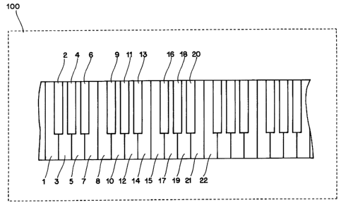
present invention, has a keyboard layout as shown in FIG. 1.
The vast majority of all useful music scales are comprised of
five, six or seven semitones. In fact, the scales containing
fewer than seven semitones are a subset of a seven semitone
scale. The present invention, therefor, is comprised of a
recognizable repeating pattern of seven keys which, when
adding a plurality of groups of these seven keys side by side,
form the new keyboard layout. As previously stated, a myriad
implementations may also be chosen to implement the same
concept, however the preferred embodiment is selected as
illustrated to minimize overall keyboard size, maximize
pattern recognition, and maintain the most possible
commonality with the traditional chromatic keyboard. The
console operator means of FIG. 4 (301-303, 305-306) permit the
musician to select one of many preprogrammed key signatures
and modes, i.e. many different musical scales. By key
signature is meant the root note assignment, e.g. if the key
CA 02250089 1998-09-18
WO 97/36282 PCT/LTS96/10957
_ 8
signature of C is selected and the MAJOR mode is selected,
referring to FIG. 2, within device 100, 1 has the musical
value C, 2 has the value D, 3 has the value E, 4 has the value
F, 5 has the value G, 6 has the value A, 7 has the value B, 8
has the value C (but one octave higher than 1), 9 has the
value D (but one octave higher than 2, etc. By mode is meant
major, minor, harmonic minor, melodic minor, phrygian, dorian,
etc.
The value of such a keyboard layout quickly becomes obvious
to those acquainted with music theory. Whereas the
traditional keyboarded musical instrument requires that the
student learn twelve different scale patterns for the major
key signatures alone, the present invention requires that the
student learn only one pattern: the pattern is, referring to
Fig. 2, keys 1, 2, 3, 4, 5, 6, 7, 8 to play, in ascending
order, the notes of one seven-note scale. That same pattern
applies to any key signature. That same pattern also applies
regardless of the mode (provided that the mode creates a scale
with seven notes), of which there are numerous modal
variations. Scales which have fewer than seven notes, such as
the various Pentatonic scales and their modes which each have
five notes, require a sequence dependent upon the scale
composition. For example, a Pentatonic Major scale is a Major
scale with deleted fourth and seventh notes. This is most
easily mapped to the present invention by muting keys 4 and 7
in Fig. 2, thus making the scale 1, 2, 3, 5, 6, 8. Keys that
are muted are displayed (304) as an "X" rather than a musical
note as an aid to the user. Most other Pentatonic scales are
variants of seven-note scales which drop the second and sixth
notes, thus the scale sequence formed by keys l, 3, 4, 5, 7, 8
allow the user to retain maximum use of the chord patterns
learned for the seven-note scale. Keys 2 and 6 in this
example are muted. Alternatively, selecting a Major scale and
ignoring keys 4 and 7 would achieve the same result as
CA 02250089 1998-09-18
WO 97/36282 PCTIUS96/10957
_ 9
selecting a Pentatonic Major scale but would defeat a feature
of the present invention, namely the elimination of unwanted
notes. The same principle applies to six-note scales such as
the blues scale, also known as Pentatonic minor with added
third. In this case, key 6 is muted, allowing maximum use of
the chord patterns learned for the seven-note scale. Thus,
instead of having to memorize how to traverse the traditional
keyboard in each of the hundreds of different possible scale
patterns, the student need learn only one pattern of the
utmost simplicity and the present invention will prevent the
sounding of notes outside of the selected scale.
The value of the present invention is also seen in the
simplicity of the patterns which must be learned in order to
play chords. Rather than attempting to simplify chords by
using electronically determined note fills or one-touch-key
chords, etc. as done in prior art, the present invention
results in a single set of simple patterns which must be
learned. These patterns apply to the various root note and
mode combinations without modification. Using the key of C
and Major mode (i.e. C Major scale) for example, the essential
chords are C Major, D Minor, E Minor, F Major, G Major, A
Minor, B Diminished, C Major Seventh, D Minor Seventh, E Minor
Seventh, F Major Seventh, G Dominant Major Seventh, A Minor
Seventh, B Half Diminished Flat Seventh. FIG. 3a illustrates
which keys of FIG. 2 on keyboard 100 comprise these chords.
As can be seen when using the patterns of FIG. 3a on keyboard
100, the patterns are extremely simple. The I chord (in this
case C major) is comprised of keys 1, 3 and 5, the first three
white keys starting with the root note. The root note is
identified as the white key immediately to the left of the
triad of alternating black keys. The II chord (D Minor) is
comprised of keys 2, 4 and 6, or the first three black keys.
The III chord (E Minor) is comprised of keys 3, 5 and 7, i.e.
three adjacent white keys played shifted right by one as
CA 02250089 1998-09-18
WO 97!36282 PCT/US96110957
compared to C Major, and once again, is every other key. The
IV chord (F Major) is comprised of keys 4, 6 and 8, i.e.
starting with the middle black key of the triad and every
other keyboard key for the next two notes. The other chords
continue in similar, easy to remember patterns, namely, every
other keyboard key starting with a particular starting key.
Similarly, the sevenths group of aforementioned chords follows
easy patterns: C Major Seventh is comprised of keys l, 3, 5
and 7, which is once again every other key beginning with key
1, in this case being all white keys, but unlike the major
chords, one extra key is added to the sequence. D Minor
Seventh is comprised of keys 2, 4, 6 and 8, i.e. every other
key beginning with key 2. The other chords among the sevenths
continues in similar, easy to remember patterns. There are,
of course, a myriad other chord types but they too have very
simple patterns, and only one pattern per chord type.
Examples of chord types include Major, Minor, Augmented,
Diminished, Major Ninth, Minor Ninth, suspended fourth, etc.,
as known in the art.
Changing to a different mode, for example from major to
harmonic minor, does not alter the patterns learned. The
basic chords in C Minor, as shown in FIG. 3e, range from C
Minor to B Diminished and follow the same patterns: 1, 3, 5,
then 2, 4, 6, then 3, 5, 7, then 4, 6, 8, etc. just like in
the C Major scale. Without learning a whole new set of
patterns for each scale, the musician can play chords in any
scale. Figs. 3a through 3f demonstrate that this concept
holds true for various key signature and mode combinations.
It can be readily seen that the present invention satisfies
the need for reducing the staggering time necessary to become
proficient with the keyboarded musical instrument in all the
various key signatures and modes while not denying the
musician the freedom to alter the chords or note patterns
played during a performance.
CA 02250089 1998-09-18
WO 97/36282 PCT/US96/10957
11
Although the above description permits full musical control
by the musician of any note combination within the select
scale, there is occasionally a need for further human
expression. For example, when the keyboard is used to emulate
the voice of a guitar, it is occasionally necessary to
simulate the bending of a guitar string, that is to say, to
vary the note pitch between two values. Prior art keyboards
satisfy this need by several means, the most popular being a
pitch bend wheel. The pitch bend wheel, therefor, is a useful
addition to the present invention to further enhance the human
expression capability of the present invention. The act of
pitch bending does in fact cause the sounding of tones not
contained in a selected scale but that is acceptable because
it is under the deliberate artistic control of the user and
does not defeat any of the objectives of the present
invention, specifically, preventing the accidental sounding of
a tone outside of the selected scale.
It is also advantageous to provide the option to the
musician of the presence of foot pedals to assist with various
keyboard functions. Such functions include:
a. Bass pedals incorporating the same simple layout pattern
of Fig. 2. This allows the musician to play richer sounding
music but without incurring as difficult a burden to learn to
play foot pedals as with the traditional arrangement. It also
permits the musician to simultaneously control one channel of
additional independent voice(s).
b. Any of the five sensing devices of Fig. 4 (301-303, 305-
306) can be made available as foot activated devices,
especially 301. This keeps the hands of the musician free to
operate the keyboard keys and yet scale alterations can still
be made.
c. Any of the other sensing devices of Fig. 4 (309-310) can
be made available as foot activated devices. This permits
CA 02250089 1998-09-18
WO 97136282 PCTIUS96/10957
12
foot-operated volume control and access to other control
functions without removing a hand from the keyboard keys.
d. Variable foot pedals such as Damper, Sostenuto or Soft,
all known in the art, can be added for finer note sound
control.
A means for entering user-defined scales is provided to
permit access to scales which may be less popular, yet to be
conceived, or which may not be known to musicians in the
mainstream culture. The means can be provided in many ways.
The preferred embodiment of data entry and scale selection,
shown in Fig. 4, consists of five sensing devices (such as
switches) and a display device (such as a liquid crystal
display or LCD) although many alternative embodiments can be
employed. Operation of this portion of the present invention
will be discussed later.
BRIEF DESCRIPTION OF THE DRAWINGS
Fig. 1 is a perspective drawing of the electronic musical
instrument keyboard.
Fig. 2 is a diagram illustrating the preferred embodiment of
the electronic musical instrument keyboard key layout of the
present invention;
Fig. 3a is a table showing the note intervals of the C Major
scale, how the notes map to the keyboard of Fig. 1, and how
the primary chords utilized in the C Major scale map to which
keys of the keyboard key layout of Fig. 2;
Fig. 3b is a table showing the note intervals of the C
Mixolydian scale, how the notes map to the keyboard of Fig. 2,
and how the primary chords utilized in the C Mixolydian scale
map to which keys of the keyboard key layout of Fig. 2;
Fig. 3c is a table showing the note intervals of the C
Dorian scale, how the notes map to the keyboard of Fig. 2, and
CA 02250089 1998-09-18
WO 97/36282 PCT/US96/10957
13
how the primary chords utilized in the C Dorian scale map to
which keys of the keyboard key layout of Fig. 2;
Fig. 3d is a table showing the note intervals of the C
Phyrgian scale, how the notes map to the keyboard of Fig. 2,
and how the primary chords utilized in the C Phrygian scale
map to which keys of the keyboard key layout of Fig. 2;
Fig. 3e is a table showing the note intervals of the C
Harmonic minor scale, how the notes map to the keyboard of
Fig. 2, and how the primary chords utilized in the C Harmonic
minor scale map to which keys of the keyboard key layout of
Fig. 2;
Fig. 3f is a table showing the note intervals of the A
Harmonic minor scale, how the notes map to the keyboard key
layout of Fig. 2, and how the primary chords utilized in the A
Harmonic minor scale map to which keys of the keyboard key
layout of Fig. 2;
Fig. 4 is a diagram illustrating the preferred embodiment of
a minimum configuration keyboard of the present invention;
Fig. 5 is a diagram illustrating the preferred embodiment of
the means to select the key signature (i.e. root note of the
desired scale) of the present invention.
Fig. 6 is a listing of a possible sequence of Major scales
which are accessible using the selection of Fig. 5;
Fig. 7 is a diagram illustrating the preferred embodiment of
the means to select the musical mode of the present invention
(i.e. Major, Minor, Harmonic minor, Melodic minor, etc.)
including the recalling of user-defined scales.
Fig. 8 is a possible sequence of scales with a root note of
C which are accessible using the selection of Fig. 7;
Fig. 9 is a diagram illustrating the preferred embodiment of
the means to quickly select a scale from among a group of
scales stored in a memory buffer, i.e. a means to quickly make
key signature and/or mode changes during a performance.
CA 02250089 1998-09-18
WO 97/36282 PCT/US96110957
14
Fig. 10 is a possible sequence of four scales stored in said
memory buffer {although four scales is not construed as the
memory buffer limit) using the selection of Fig. 9;
Fig. 11 is a diagram illustrating the preferred embodiment
of the means to define the user-defined scales of the present
invention, i.e., to enter the notes which comprise the user-
defined scales:
Fig. 12a is a first example of how scales are defined, using
the selections of Fig. 11;
Fig. 12b is a second example of how scales are defined,
using the selections of Fig. 11;
Fig. 12c is a third example of how scales are defined, using
the selections of Fig. 11;
Fig. 13 is a diagram illustrating the preferred embodiment
of the means to store scales in a memory buffer for later
recall;
Fig. 14a is a listing of user actions to store scales, using
the selections of Fig. 13;
Fig. 14b is a listing of user actions to store scales, using
the selections of Fig. 13, continued from Fig. 14a;
Fig. 14c is a listing of user actions to store scales, using
the selections of Fig. 13, continued from Fig. 14b;
Fig. 15 is a block diagram defining the minimum
configuration keyboard preferred embodiment of the present
invention;
Fig. 16 is a block diagram illustrating the rich
configuration embodiment (RCE) keyboard preferred embodiment
of the present invention;
Fig. 17 is a diagram illustrating the preferred embodiment
of a bass pedal implementation using the seven note per octave
concept of the present invention and shown connected to the
keyboard of Fig. 4;
CA 02250089 1998-09-18
WO 97/36282 PCT/US96/10957
Fig. 18 is a block diagram defining the preferred embodiment
of the bass pedal option embodiment (BPE) referenced in Figs.
10 and 11.
BEST MODE FOR CARRYING OUT INVENTION
Three embodiments of an electronic musical instrument in
accordance with the present invention will be described: a
minimum configuration embodiment (MCE) which is a musical
instrument digital interface (MIDI) keyboard with no internal
sound module or MIDI sequencer. Another embodiment, a rich
configuration embodiment (RCE) - a MIDI keyboard capable of
stand-alone operation, including internal sound module and
MIDI sequencer, will be described later in much less detail.
A third embodiment, a base pedal embodiment (BPE),
constituting bass pedals will be described also in much less
detail for the main purpose of indicating that the concept of
the present invention can be applied to more than just a
finger-operated keyboard. The concept behind the present
invention is not limited to MIDI-interfaced keyboards,
however, MIDI is currently the widely accepted standard
keyboard interface and the most logical existing choice for an
implementation of the present invention. Any references to
MIDI should not be construed as a limitation upon the present
invention. Any interface which satisfies the intent of MIDI
can be substituted.
1. MINIMUM CONFIGURATION EMBODIMENT
The minimum configuration embodiment (MCE) is illustrated in
Fig. 4. A block diagram of the minimum configuration
embodiment is shown in Fig. 15. The following table shall
serve as a cross-reference between the drawing items of Figs.
4 and 15. The following description of the MCE references
Figs. 4 and 15.
CA 02250089 1998-09-18
WO 97/36282 PCT/US96/10957
16
Fig . 4 Item ( s ) Fig. 15 Item (s ) Comment
300 900 Min Configuration
Keyboard
301-305, 308-310 907 User Control
Operators
306 905 Display
307 901 less interface Keyboard key
portion of the operators, interface
operator is inherent in 901,
not shown in 307
The primary internal functional units are described as
follows.
Keyboard key operator 901 is comprised of a plurality of
keyboard keys arranged in the order shown in Fig. 2 and again
shown in Fig. 4 item 307, a means for detecting that a key is
actuated, and optionally a means for detecting how hard and/or
how quickly a key is actuated or released (known in the art as
pressure sensing or after-touch, and velocity sensing).
Information is transmitted by output interface 902 to the
other internal functional units.
Bass pedal interface 903 contains input circuitry which
accepts pedal actuation information from bass pedal operator
950 via output 951. Pedal actuation information consists of
data representing which pedals are being activated, and
optionally how hard and/or how quickly a pedal is actuated or
released. Output interface 904 contains output circuitry
which provides the pedal actuation information to the other
internal functional units.
Display 905 consists of a multiple-character, multiple-line
display device. The preferred embodiment is a 2 line x 24
character liquid crystal display (LCD), although this should
CA 02250089 1998-09-18
WO 97/36282 PCT/US96/10957
17
not be construed as a limit placed upon the MCE. The display
receives the information to be displayed using input interface
906.
Keyboard panel operator 907 is comprised of the remaining
user interface devices of the MCE. This consists of an input
sensor 301 for the purpose of implementing the "NEXT" user
input, an input sensor 302 for the purpose of implementing the
"+" user input, an input sensor 303 for the purpose of
implementing the
"-" user input, an input sensor 304 for the purpose of
implementing the "~" user input, an input sensor 305 for the
purpose of implementing the "u" user input. Input sensors
301-305 are preferably momentary contact switches although
this should not be construed as a limit placed upon the MCE.
Additionally, keyboard panel operator 907 also consists of an
input sensor 308 for the purpose of implementing the pitch
bend user input, input sensor 309 for the purpose of
implementing the volume control user input, and a plurality of
input sensors 310 for the purpose of implementing other
miscellaneous functions such as turning the power on/off and
options such as allowing MIDI channel assignments to various
sections of the keyboard and bass pedals, sensitivity
adjustments of the pitch bend sensor, sensitivity adjustments
of the keyboard keys, sensitivity adjustments of the bass
pedals, etc.
Foot panel interface 909 contains input circuitry which
accepts data from the foot panel operator 960 by way of output
961. Foot panel information consists of data representing
such information as, but not limited to, scale selection,
keynote selection, mode selection, volume, sustain, breath,
etc. Output interface 910 provides foot panel information to
the other functional units.
Predefined scale memory 911 contains data on each predefined
scale type including the number of notes, the note intervals
CA 02250089 1998-09-18
WO 97/36282 PCT/LTS96110957
18
and a collective name for the plurality of notes of the scale.
It is preferable that predefined scale memory 91I be
implemented using some manner of alterable non-volatile memory
such as, but not limited to, FLASH EPROM (erasable
programmable read-only memory) or EEPROM (electrically
programmable read-only memory) or battery-backed SRAM (static
random access memory) to allow upgrades to the stored
information although non-alterable memory such as ROM will
satisfy the essential storage requirement of non-volatile
storage. Output interface 912 provides predefined scale
memory data to the other functional units. If an alterable
non-volatile memory device is utilized for 911, interface 912
would be bi-directional instead of an output interface only.
User-defined scale memory 913 stores/recalls data on each
user-defined scale type including the number of notes, the
note intervals and a collective name for the plurality of
notes of the scale. It is preferable that user-defined scale
memory 913 be implemented using some manner of alterable non-
volatile memory (such as, but not limited to, FLASH EPROM or
EEPROM or battery-backed SRAM) to allow persistence of stored
information although volatile memory such as non-battery
backed SRAM or DRAM (dynamic random access memory) will
satisfy the essential storage requirement. Output interface
914 provides a way to send/receive data to/from the user-
defined scale memory. Predefined scale memory and user-
defined scale memory could be combined into one component,
EEPROM for example, to reduce the number of components in the
implementation. Such a combining still permits both functions
to exist.
Scale sequence memory 915 stores/recalls sufficient
information as to uniquely define an order of scales to be
selected from memory items 911 and 913. It is preferable that
user-defined scale memory 915 be implemented using some manner
of alterable non-volatile memory (such as, but not limited to,
CA 02250089 1998-09-18
WO 97/36282 PCT/US96/10957
19
FLASH EPROM or EEPROM or battery-backed SRAM) to allow
persistence of stored information although volatile memory
such as non-battery backed SRAM or DRAM will satisfy the
essential storage requirement. The scale sequence memory is
used as a circular buffer by the control 919. For example, if
the user wishes to rotate through a sequence of seven
different scales at various points in playing the keyboard,
seven scales are present in 915. A scale sequence pointer in
control 919 contains a memory address which is used to locate
information for the current scale. When the user inputs the
"NEXT" command (item 907, specifically item 301), the pointer
is advanced to the next scale in 915. Had that "NEXT" command
caused the eighth scale to be referenced, instead the pointer
is set to the first scale in this example. That is, the
pointer wraps around in a circular manner through the valid
scale sequence entries. Output interface 916 provides a way
to send/receive data to/from the scale sequence memory. Scale
sequence memory 915 could be combined with memory 911 and
memory 913 in an appropriate electrical component such as
EEPROM to reduce the number of components in the
implementation. Such a combining still permits the three
functions to exist.
MIDI interface 917 provides the interface which allows the
MCE to transmit (and optionally receive and pass through) MIDI
information to other MIDI devices. MIDI interface 917
provides data to and receives data from the other functional
units by way of the bi-directional interface 918. MIDI output
922 is essential whereas MIDI input 923 is optional. MIDI
input 923 permits other MIDI devices such as a sequencer to
setup parameters in the MCE which may include scale sequence
information, user-defined scale information, predefined scale
information, key sensitivity information, etc. The MCE user
interface programs scales in the form of a sequence of notes.
A sequence of notes can therefor be input to the MCE using
CA 02250089 1998-09-18
WO 97/36282 PCT/US96/10957
MIDI input 923 if desired as an option. The MIDI through
output 924 is possible only if MIDI input 923 is present. The
purpose of The MIDI through output 924 is to provide a quick
MIDI loopback through the device for control of multiple MIDI
slave devices from a single MIDI master device.
Control 919 provides all logic necessary to permit the
orderly communication and control of all the above functional
units. The control is preferably a microcontroller although
the function can be accomplished with a wide variety of
alternatives such as, but not limited to, a microprocessor,
ASIC (application-specific integrated circuit), personal
computer, discrete logic, etc. Bi-directional interface 920
provides the means for control 919 to interact with the other
functional units.
Internal communications bus 921 is the means for internal
communications between the functional units.
The internal functional units are connected as follows.
Keyboard key operator 901 provides key actuation information
using output 902 to an internal communications bus 921. The
information is received from bus 921 by control 919 through an
input/output interface 920. Control 919 constantly keeps track
of which scale is currently selected. Display 905 receives
information to be displayed on input interface 906. Input
interface 906 is connected to bus 921. The display 905
displays information to the user to facilitate a user-friendly
method for selecting predefined scales, user-defined scales
and scale sequences, and to define the user-defined scales and
sca3e sequences. Keyboard panel operator 907 consists of all
panel operator devices shown in Fig. 4 (301-305, 308-310),
i.e. input devices. Operator 907 provides information using
output interface 908. Output interface 908 is connected to
bus 921. An optional external device, bass pedal operator
950, sends information by the output interface 951 to a bass
pedal interface 903. The bass pedal interface 903 sends
CA 02250089 1998-09-18
WO 97/36282 PCT/US96/10957
21
information by output interface 904 to bus 921. Another
optional external device, foot panel operator 960 sends
information using output interface 961 to the foot panel
interface 909. Foot panel interface 909 sends information
using output interface 910 to bus 921. MIDI Interface 917
sends and receives information to/from bus 921 using
input/output interface 918. MIDI interface 917 communicates
with external MIDI devices using MIDI output interface 922,
optional MIDI input interface 923 and optional MIDI through
interface (i.e. output interface) 924. Predefined scale
memory 911 sends scale information to bus 921 using output
interface 912. User-defined scale memory 913 sends and
receives information to/from bus 921 using input/output
interface 914. Scale sequence memory 915 sends and receives
information to/from bus 921 using input/output interface 916.
The manner in which the user of the present invention
interfaces with the minimum configuration embodiment, and in
which the internal functional units interact is described as
follows:
1. When the MCE is turned on (using item 310), the control
919 reads scale sequence information from memory 915 (if
memory 915 is non-volatile, otherwise default information is
used) and reads note data from memory 911 if the first scale
in memory 915 is a predefined scale or reads note data from
memory 913 if the first scale in memory 915 is a user-defined
scale. By first scale stored in memory 915 is meant the scale
indicated by the aforementioned scale sequence pointer. Thus,
the scale used when the unit was last powered on is the
default scale when the unit is next turned on, or a default
scale if no such information is found. The display 306 of
Fig. 4 and 905 of Fig. 15 shows the root note of the selected
scale, the mode (e. g. Major, Minor, etc.) and the notes
contained in the scale (e. g. C, D, E, etc.).
CA 02250089 1998-09-18
WO 97/36282 PCT/US96110957
22
2. The user can select a different root note as when a
different key signature is contained in the music being
played. Referring to Figs. 5 and 6, actuating the "+" input
sensor button 302, one of the two keynote select user
buttons, advances the selected scale from C Major to Db Major
and reflects the result on display 306. Internally, the MCE
control 919 reads the state of input sensor button 302,
computes the desired result, displays the desired result on
display 306 and begins to interpret any actuated keyboard keys
307 in correspondence to the scale selected. This pattern of
action is common to any manner of means to select an active
scale (i.e. root note and mode). Actuating "+" again advances
the selected scale to D Major. Actuating the "-" input sensor
button 303 would drop the selected scale one semitone to Db
(flat) Major, and thus the keyboard keys 1 through 8 of Fig. 2
are programmed to Db, Eb, F, Gb, Ab, Bb, C respectively. All
twelve root notes are accessible in this described manner.
Actuating and holding 302 or 303 serves as a repeat function,
allowing a new root note to cycle more rapidly. For example,
if the current scale is A Major and Eb Major is desired, the
"+" button 302 is actuated and held, causing the scales to
more quickly advance to Eb Major. Alternate embodiments are
certainly possible, such as, but not limited to, a single
keynote selection "jog wheel", a means known in the art, or a
mouse pointing device and a larger screen could be used to
very rapidly select root note, (for example, all root notes
may be displayed on the screen and "clicking" on the desired
note selects it) or data entered by means of an optional MIDI
input could select the root note. The MCE is not limited by
the order of root notes shown in Fig. 6, as alternate orders
of the root notes may also have advantages, however the shown
order is selected for simplicity; neither is the MCE limited
only to the described preferred manner of selecting root
notes.
CA 02250089 1998-09-18
WO 97/36282 PCT/US96/10957
23
3. The user can select a different scale mode as illustrated
by the following example using Figs. 7 and 8. The two mode
select user buttons, 304 and 305 provide the means for the
user to select a different scale mode. If the currently
selected scale is C Major and C minor is desired, the
input sensor button 305 is actuated to change the selected
scale to C Dorian, i.e. the mode is changed but the root note
remains the same. The resultant display is shown in Fig. 8
including the root note (which was not changed), the name of
the newly-selected mode , the notes which comprise the mode
beginning with the root note C in ascending order, and
implicitly, which keyboard keys are active and which keys are
muted (X would indicated a muted key, i.e. an unused key).
Four more actuation's of 305 results in the selection of C
Minor, and thus the keyboard keys 1 through 8 of Fig. 2 are
programmed to C, D, Eb, F, G, Ab, Bb respectively. Alternate
embodiments are certainly possible, such as, but not limited
to, a single keynote selection "jog wheel", a means known in
the art, or a mouse-pointing device enabling the user to
select a mode from a menu displayed on a screen large enough
to display multiple, simultaneous choices, or data entered by
means of an optional MIDI input could select the mode. The
MCE is not limited by the described interface for mode
selection or by the order of modes shown in Fig. 8, as
alternate orders of the root notes may also have advantages,
nor by the number of modes provided. However the shown order
of modes is selected to reflect a logical progression of
traditional modes, then a looser ordering of other modes using
seven notes, six notes and five notes. Many other logical
groupings are possible. Referring again to Fig. 8, C
Pentatonic minor illustrates how muted keys are reflected in
display 306, the notes being C X Eb F G X Bb. This indicates
that keyboard keys 1 through 7 (and of course repeating this
obvious pattern throughout the remainder of the keyboard)
CA 02250089 1998-09-18
WO 97136282 PCT/L1S96/10957
24
represent C, muted, Eb, F, G, muted and Bb, respectively.
Hence neither keys 2 nor 6 cause a musical note to be
transmitted on the MIDI output 922. Implicitly, the MCE shows
the user what the value of each keyboard key is and which keys
are active and which keys are not active (muted).
9. The scale select interface permits the user to
sequentially select from among a group of user-chosen scales
which are desired for easy access. The following example of
Fig. 9 and Fig. 10 illustrates this concept. Fig. 10
illustrates the circular buffer concept previously described.
The user previously has chosen four scales for easy sequential
access. If C Major is the current scale selection seen in
Fig. 10, after actuating the "NEXT" input sensor button 301,
i.e. the scale select button, A Minor becomes the currently
selected scale and is displayed on display 306 as shown.
Actuating "NEXT" again results in C Major. Actuating "NEXT"
again results in C Pentatonic major as the currently selected
scale, comprised of notes C, D, E, G and A. Actuating "NEXT"
again returns to the start of the sequence at C Major. As
with all cases except while defining user-defined scales or
while defining the actual scale sequence, the scale displayed
on display 306 is also the scale currently active on keyboard
keys 307. Although the example shows four scales in the
circular memory buffer (915 and 919), this should not be
construed as a limitation upon the MCE. Likewise, as in 2.
and 3. above, other means can be used to select scales, such
as, but not limited to, an optional foot switch contained in
960 of Fig. 15, or a mouse-pointing device in conjunction with
a display. which can display many more simultaneous characters.
The described embodiment is not a limitation upon the present
invention.
5. The user scale-definition interface is shown in Fig. 11.
This permits the user to define a scale not already stored in
the predefined scale memory. While defining a user-scale, the
CA 02250089 1998-09-18
WO 97/36282 PCT/US96/10957
keyboard keys 307 are not intended to be active in the MCE,
although they could remain active in the scale selected prior
to entering the user scale-definition. Fig. 12a shows a 14
step example resulting in the storage of a seven-note scale
under the default title "User defined 1". "+" and "-", 302 and
303, are simultaneously actuated to enter into user scale
definition mode, resulting in a screen display on item 306,
which reminds the user about how to perform said scale
definition. Entering "+" calls up the default starting note,
i.e., the root note which was active prior to entering into
user scale definition. This example assumes that root note
was C. C is the intended root note in this example also.
Actuating "NEXT', 301, accepts C as part of the user-defined
scale and displays the next note, C# (sharp). (Optionally, an
interface may be provided that allows the user to choose if
sharps or flats should be used in this ascending sequence of
note selection although that detail is not essential to the
MCE definition.) C# is not desired. "+" is actuated,
advancing C# to D. Actuating "NEXT" accepts D as part of the
user-defined scale and displays the next note, D#. Actuating
"+" twice followed by "NEXT" accepts F as the next note and
advances to F#. Actuating "NEXT" again accepts F#. Actuating
"+" followed by "NEXT accepts G# as the next note. Actuating
"NEXT" again accepts A. Actuating "+" advances to B. At this
point in the sequence, the user can either actuate "NEXT" to
accept B, and since there are no more unique notes, user scale
definition is complete and a save and exit results, or, the
user can actuate "-" to indicate that the seventh key in the
sequence shall be muted, or the user can simultaneously
actuate "+" and "-", the normal way to exit the mode and save
results. Upon exiting the scale definition, the notes are
saved in the user-defined scale memory 913 under the title
User defined 1.
CA 02250089 1998-09-18
WO 97/36282 26 PCT/US96/10957
Seeing the display contents shown at sequence I4, namely
"User defined 1" without the "entry?" text, confirms that this
note combination has been saved. See 5. below for further
discussion. Under said title, the notes can be later recalled
and transposed in accordance with the interface described in
Fig. 6 and text describing the operation of Fig. 6 (2. above).
Actually, the precise notes entered do not need to be saved,
but rather the intervals between the notes is the important
information. Any root note can be assigned as the first note.
However, insofar as the user is concerned, it appears that the
notes entered by the user comprises the stored information.
Either concept, storing the notes or storing the intervals
between the notes can accomplish the same desired result. It
is actually preferred to store the interval information, since
that simplifies the task described in 6, below. Fig. 12b
illustrates a second example sequence of keystrokes, showing
how the "-" is used to mute every keyboard key which would
otherwise be the fourth note of every octave. Fig. 12c shows
another case in which the user desires to enter a scale that
does not start with the keyboard's currently valid root note.
In this example, it is assumed that the currently selected
root note is C. The user enters scale definition as before
and actuates the "-" button three times followed by actuating
"NEXT", resulting in A as the root note for the new scale
definition. This saves the user the task of transposing the
notes before entering them into the MCE.
6. As further assistance to the novice musician, this same
interface described in 5. above can be used to assist in
selecting an appropriate scale already contained in the MCE,
whether in the predefined scale memory or in the user-defined
scale memory. Upon exiting after a user-defined scale is
defined, the control 919 initiates a search through predefined
scale memory 911 and user-defined scale memory 913 to check
for duplication of the note patterns. By note patterns is
CA 02250089 1998-09-18
WO 97/36282 PCT/US96/10957
27
meant the interval (in semitones) between the notes of the
scale. For example, The note intervals of the C Major scale
are 2 (from C to D) , 2 (from D to E) , 1 (from E to F) , 2 (from
F to G) , 2 (from G to A) , 2 (from A to B) and 1 (from B to C) .
In fact, this is the definition of a Major scale. If the user
was unsure which scale to choose for a particular piece of
music, the user could look through the music, enter the notes
used into one of the user-defined scale memories, and then
upon exiting, if the MCE matches the pattern of intervals to a
scale already entered, the displayed result shown in Fig. 12a
sequence 14 (for example) is not what is displayed, but rather
the scale found to match the current user entry is displayed.
For example, if the final result in sequence 13 of Fig. 12a
were the notes C, D, E, F, G, A, B, sequence 14 would display
the following:
C Major (Ionian) C D E F G A B
indicating that the entered notes match to the root note C and
Major or Ionian mode. This serves as the indication to the
user that the notes entered correspond to an existing scale
and what that scale is. This can be a tremendous benefit to
any musician, but especially the novice.
7. The scale sequence interface is shown in Fig 13. Figs.
14a through 14c shows an example of how a sequence of scales
is entered. This permits the user to later cycle through a
sequence of scales with a single key actuation. Figs. 14a
through 14c show a 46-step example resulting in the storage of
the four scale sequence used in the example of Fig. 9. "'~" and
"u", 304 and 305 of Fig. 13, are simultaneously actuated to
enter into scale sequence definition mode, resulting in a
screen display which reminds the user about how to perform
said scale sequence definition. Entering "~" calls up the
default starting scale, i.e. the root note and mode which was
active prior to entering into scale sequence definition. This
example assumes that root note was C and the mode was Major.
CA 02250089 1998-09-18
WO 97/36282 PCT/US96/10957
_ 28
C Major is the intended first scale in this example.
Actuating "NEXT', 301, accepts C Major as the first scale in
this sequence and displays the next mode, C Dorian. "~" is
actuated four times, resulting in C Minor being displayed, but
A Minor is the next desired scale. "-" is actuated three
times which decrements the root note such that A Minor is
selected. "NEXT" is actuated to enter A Minor as the next
scale in the sequence, shown at sequence 11 of Fig. 14a. The
example continues until the last desired scale is entered at
sequence 46 in Fig. 14c. Scale sequence definition mode is
exited by simultaneously actuating "'~" and "~". As previously
described, this process of stepping through root notes and
modes can be accelerated by pressing and holding the various
described buttons (301-305 as appropriate). The described
implementation should not be construed as a limitation of the
present invention. For example, a mouse pointing device and a
display device large enough to simultaneously show all modes
and all root notes could be used to very rapidly select the
scale sequences, albeit a presently more expensive
implementation. A single rotary device such as a "jog wheel"
could replace the "~" and "u" buttons, etc. A 4 x 24 LCD
display could allow the user to visualize more moves at a
time. The essential concept is the same regardless of a
myriad possible implementations. Actually, the precise scale
names do not have to be stored in memory 915, but rather a
code uniquely indicating which scale and root note is desired
to be referenced. There are only twelve possible root notes,
and only thirty-nine possible modes described in the MCE,
although as mentioned, the thirty-nine modes is not to be
considered a limitation placed upon the present invention.
Thus, as few as 9 binary bits of storage permit unique
referencing of the 12 x 39 = 468 possible scales shown in the
MCE. This technique minimizes the required memory size for
storing scale sequence information. Note that the described
CA 02250089 1998-09-18
WO 97/36282 PCT/US96/10957
29
embodiment makes no provision for editing the scale sequence
but rather forces the user to enter an entirely new sequence.
This is not to be construed as a limitation to the present
invention. Such an editing feature is desirable but non-
essential to the description of the MCE. Also, being able to
select from among a number of different stored scale sequences
is desirable, but again is not vital to the essential concept
of the present invention. Also, the ability to save sequences
of scales and/or user-defined scales under more user-friendly
titles such as the name of a song is desirable and the absence
of such a description is not a limitation upon the present
invention.
8. Musical notes are initiated by selecting or actuating
keyboard keys (307 of Fig. 4 and 901 of Fig. 15) in accordance
with the selected scale which appears on the display (306,
905). The keyboard key operator 901 passes key
actuation/release information via output 902 to internal bus
921 to bi-directional interface 920 to control 919. Control
919, which in communication with memory items 911 and 913 and
915, computes corresponding note information. Note
information is sent from control 919 via bi-directional
interface 920, then internal bus 921, then interface 918
(which as previously mentioned may be an input interface or a
bi-directional interface) to MIDI interface 917. MIDI
interface 917 communicates note information to external MIDI
devices such as sequencers and sound modules via MIDI output
interface 922.
2. RICH CONFIGURATION EMBODIMENT
The rich configuration embodiment (RCE) block diagram,
shown in Fig. 16 comprises the MCE and a number of additional
functional units. The purpose of describing an embodiment
with greater integration of functional units is to demonstrate
that the fundamental concepts of the present invention extend
to all manner of keyboard musical instruments or alternate
CA 02250089 1998-09-18
WO 97/36282 PCT/US96/I0957
representations thereof, such as, but not limited to, keyboard
interface simulated on the screen of a personal computer. The
units are described as follows.
Keyboard key operator 1001 is the same as 901 as described
previously. Keyboard key operator 1001 passes output
information on output interface 1002 which is in communication
with internal bus 1021.
Bass pedal interface 1003 contains input circuitry which
accepts pedal actuation information from bass pedal operator
1050 via output 1051. Pedal actuation information consists of
data representing which pedals are being activated, and
optionally how hard and/or how quickly a pedal is actuated ar
released. Output interface 1004 contains output circuitry
which provides the pedal actuation information to the other
internal functional units via internal bus 1021. Bass pedal
interface 1003 also contains input circuitry which accepts
foot sensor data from bass pedal operator 1050 via output
1051. This additional data comprises such information as bass
pedal voice selection. For example, the bass pedals are not
restricted for use as a bass instrument only, but can be any
available voice such as percussion or lead saxophone.
Display 1005 consists of a graphics display device capable
of displaying all root note choices, all mode choices, and
which can provide user-friendly menus for selecting and
assigning voices, acoustic environment, rhythm, etc. The
preferred embodiment is a high resolution liquid crystal
display (LCD), although this should not be construed as a
limit placed upon the MCE. The display receives the
information to be displayed using input interface 1006 which
is in communication with internal bus 1021.
Keyboard panel operator 1007 consists of various input means
to allow the user to quickly make root note, mode, voice,
acoustic environment, rhythm, etc. choices. The preferred
embodiment is a rotary-type input sensor for root note
CA 02250089 1998-09-18
WO 97/36282 PCT/US96/10957
- 31
selection (and to aid in user scale definition), a rotary-type
input sensor for mode selection (and to aid in user scale
definition), a rotary-type input sensor for the remaining
choices, all using a menu-driven system. Operator 1007 in
communication with internal bus 1021 via output 1008.
Foot panel interface 1009 contains input circuitry which
accepts data from the foot panel operator 1060 by way of
output 1061. Foot panel information consists of data
representing such information as, but not limited to, scale
selection, keynote selection, mode selection, volume,
sustain, breath, etc. Output interface 1010 provides foot
panel information to the other functional units.
Predefined scale memory 1011, user-defined scale memory 1013
and scale sequence memory 1015 operate as in the MCE
description (items 911, 913 and 915 respectively). These
units are all in communication with internal bus 1021 via
interfaces 1012, 1014 and 1016 respectively.
MIDI interface 1017 operates in the same manner as 917 in
the MCE description. MIDI through and MIDI input are not
optional but rather are always provided.
Control 1019 is preferably a microcontroller and facilitates
internal communication and control of all functional units.
It is in communication with internal bus 1021 via bi-
directional interface 1020.
Keyboard setup memory 1027 provides a means to save all
voice, acoustic, scale, and other information pertaining to
recalling keyboard settings such that the same sound is
reproducible in future sessions. Memory 1027 is in
communication with internal bus 1021 via bi-directional
interface 1028. The keyboard setup store and recall functions
constitute part of the previously described user-friendly
interface.
A multi-channel sequencer and memory 1025 is in
communication with bus 1021 via bi-directional interface 1026.
CA 02250089 1998-09-18
WO 97!36282 PCT/US96/10957
- 32
The multi-channel sequences permits storing and recalling
files of musical notes for the purpose of saving and playing
back music. It permits the combining of notes currently being
played on the keyboard keys with previously stored notes
transposed to the currently selected scale. The preferred
memory means is a combination of volatile memory such as DRAM
and non-volatile memory such as a floppy disk drive or a hard
disk drive, although other memory types may also be used. A
sequences user interface, part of the previously mentioned
user-friendly interface, facilitates easy storing and
recalling of said files. The output of sequences 1025 is
provided via output interface 1036 to the sound generation
1029 rather than using bus 1021 because of the high volume of
data.
Sound generation, sampling and channel mixing 1029 is in
communication with bus 1021 via bi-directional interface 1030.
It accepts the bulk of its input information from output 1036.
Unit 1029 incorporates a memory means which stores information
that is used to construct sounds. Unit 1029 converts note and
voice information from the multi-channel sequences, using said
memory means. It combines the various voices in a user-
determined ratio (known as audio mixing) as requested by user
interface 1027 and outputs the resultant sound data via output
interface 1038 to the digital acoustic environment generation
1031.
The Digital acoustic environment generation 1031 is in
communication with bus 1021 via bi-directional interface 1032.
This unit uses digital signal processing techniques to create
the illusion of different acoustic environments such as
various room sizes, various room liveliness factors, echo
effects, reverb effects, etc. Commands are received from bus
1021. Audio input data is received from sound generation,
sampling and mixing 1029 from output 1038. Unit 1031 outputs
multiple channel audio data via output interface 1040.
CA 02250089 1998-09-18
WO 97/36282 PCT/US96/10957
33
Multiple channel audio amplifier 1033 receives multiple
channel audio data from output 1040. It provides a headphone
interface and also amplifies audio data so that audio output
can be reproduced by audio transducers 1035 via output
interface 1042.
Multiple channel audio transducers 1035 receives multiple
channel amplified audio from output interface 1042 and
converts the audio information into sound.
3. BASS PEDAL EMBODIMENT (BPE)
A description of a bass pedal implementation is included to
demonstrate that the concept of the seven keys per octave of
present invention can be applied to musical instruments other
than keyboards, although bass pedals originated for
supplementary use with keyboard-style devices. Fig. 17 shows
the bass pedal preferred embodiment 1100 in communication with
the MCE 300 by bass pedal output 1104. The bass pedal
preferred embodiment consists of a plurality of pedals 1101
and 1102 arranged in a repeating pattern of seven pedals, in
accordance with the seven keys per octave concept of the
present invention. A plurality of Input sensors 1103, such as
switches, permits foot selection of any variable operating
features which may be desired.
Fig. 18 illustrates the internal workings of the bass pedal
implementation 1200. A control 1207 receives pedal actuation
information from bass pedal operator 1201 (refer to pedals
1101 and 1102 of Fig. 17) by means of bass pedal operator
output interface 1202, internal bus 1209 and bi-directional
interface 1208. Control 1207 also receives bass panel
operator inputs (refer to input sensors 1103) from output
interface 1206, internal bus 1209 and bi-directional interface
1208. Note information and user foot selection information is
sent from control 1207, via interface 1208, bus 1209, input
interface 1204 to bass pedal interface 1203. Bass pedal
interface 1203 outputs said information via output interface
CA 02250089 1998-09-18
WO 97/36282 PCT/US96110957
34
1211 to the keyboard. It should be noted that bass pedal
interface 1203 could be implemented using a MIDI interface
such as 1017-1023 of Fig. 16 although the interface need not
be as complex as a MIDI interface.
SUT~ZARY
4. The minimum configuration embodiment and accompanying
descriptions demonstrate that the concept of using seven keys
per octave and electronically mapping said keys to the notes
of a scale constitutes a dramatic simplification in the art of
learning, performing and composing music.
The rich configuration embodiment employs the essential
concepts of the present invention and demonstrates how the
concepts can combine with other devices to produce a stand-
alone complex music workstation. A similar end result can be
achieved by combining the MCE with external units which take
the place of the additional units described in the RCE
although there are distinct advantages of integrating the
functional units together. Such advantages include: reduced
complexity for the user, rapid setup of equipment and
equipment state, etc.
The essential concept of the present invention can be
applied to other musical instruments such as bass pedals, or
any other instrument in which there is opportunity to
electronically remap the user inputs to musical notes.
While there is shown and described the present preferred
embodiment of the invention, it is to be distinctly understood
that this invention is not limited thereto but may be
variously embodied to practice within the scope of the
following claims.
I claim: