Note: Descriptions are shown in the official language in which they were submitted.
24. SEP, 1998 11.07 VEREENIGDE DEN HAAG N0, 1707 P. 44
SEP 24 '98 04~59RM
Title: Assembly of nestable wheelchairs and wheelchair for
use in such an assembly.
The invention relates to an assembly of a number of
wheelchairs according to the~preamble of claim 1. Such an
assembly is known from US 5 354 079.
The known assembly comprises at least two children's
strollers, provided with a frame, a number of wheels and a
bucket like~seat. The frame is somewhat wedge-shaped, such
that the front wheels can pass between the rear wheels of a
stroller positioned in front thereof. The frame of the
strollers have upper and lower crossbars, whereby the seat
l0 has a series of ribs on the=bottom and a hanger bracket
mounted on the back thereof. In the seating position the back
of she seat rests against the upper crossbar and the lower
crossbar- rests in a groove between a pair of ribs on the
bottom of the seat. The orientation of the seat is determent
by which groove the lower crossbar rests in_ In a nested
position the bucket-like seat is pulled upward, such that it
can be suspended from the upper crossbar by:means of an
indent of the hanger bracket. In this position the bottom is
completely free from the lower crossbar, which means that the
bucket-like seat can swing around zhe upper crossbar. when
nested the front side of the seat of a rearward wheelchair
abuts against the backside of the seal of a wheelchair nested
in front thereof, such that-'the bucket-like seats are
positioned one behind the other, the rear wheels of the two
nested wheelchairs being close together.
When a wheelchair of this known assembly is to be used
the most rearward wheelchair will be pulled from the nested
position, after which the stroller has to be prepared by
lowering the seat onto the lower crossbar. This will be
3o awkward, especially to a disabled person or to a person
carrying for example the child to be seared, luggage,
merchandise or the like. Furthermore, such wheelchair may be
dangerous since it may partly collapse when the child is
positioned into the -seat, since the seat can be positioned
AMENDED SHEET
CA 02250184 1998-09-25
24, SEP, 1998 11.07 VEREENIGDE DEN HAAG N0. 1707 P. 45
SEP 24 '98 04:59AM
new page la
improper, for example with a rib on the lower crossbar. This
would mean that the front side of the seat could pass the
lower crossbar, thus throwing the child forward out of the
seat. Moreover, such stroller will be hard to handle,
especially when scaled up to the size suitable for a gro~srnup,
since the bucket like seat will then be heavy and relatively
large, which makes it hard to manoeuvre. Before a stroller
can be nested i.n this known assembly the bucket like seat has
to be brought into said nesting position, whereby the seat
has to be raised such that a dent in the hanger bracket can
rest on the upper crossbar. Once again, this manoeuvre can be
awkward for a person using the stroller, which will often
prevent a user of said stroller to indeed nest said stroller
after use for it is taking to much time and enexgy.
Furthermore, since the bucket like seat is not firmly
connected to the frame, the strollers of such know assembly
have a frail and difficult construction, which can be easily
damaged, especially the hanger bracket and the chassis_
The known assembly can be used, for instance, at
airports, in hospitals and nursing homes, department stores
and like establishments visited by varying populations. The
strollers are intended for »ublic or at least semi-public
use. The use of such an assembly will now be explained with
reference to an airport.
At any moment of the day, several wheelchairs are
arranged together at a central point, for instance at an
entrance of an airport. A passenger arriving at the airport
sits down in one of the wheelchairs, with or without
assistance from, for instance, a fellow traveller or an
3o airport employee. Then the user of the wheelchair proceeds to
an airplane, where the wheelchair is left behind when the
user takes his seat in the airplane. The wheelchair may be
used zqsin by another passenger for anothex displacement or
is wheeled back empty to the above-mentioned or similar
central point in due course.
AMENDED SHEET
CA 02250184 1998-09-25
24. SEP. 1998 11.07 VEREENIGDE DEN HAAG N0, 1707 'P. 46
SEP 24 '98 04:59RM
new page Ib
Normal wheelchairs have as a disadvantage that the
wheelchairs occupy a great deal of space in unused condition.
The wheelchairs are placed together, for instance in arrow
side by side. It will be clear that this is undesirable,
since space at an airport but also in, for instance,
hospitals, residences for disabled or older people and the
like, is limited. Moreover, the wheelchairs arranged together
make a disorderly, chaotic and hence unattractive impression
and can be a hindrance and even dangerous to other passers-
by, such as visitors and employees. A further disadvantage is
that the wheelchairs, when they are not, or no longe_, in use
and have been left at a different point than the above-
mentioned central
'ENDED SHEET
CA 02250184 1998-09-25
WO 97/35536 PCT/NL97/00153
2
arrangement point, they have to be returned to that central
arrangement point one by one, which is time-consuming and
strenuous, and hence expensive and unpleasant. .
It has previously been proposed to make wheelchairs
collapsible, so that in the condition where they are not used
they take up little or at least less space than in a service
position. This is undesirable for wheelchairs for public or
at least semipublic use, since the wheelchairs are not ready
for use in such a storage position. An intended user or
helper must then first unfold the wheelchair or at least make
is ready for use, whereafter it can be used. This is
undesirable, notably in places where time is limited.
Moreover, making such a wheelchair ready for use is not easy.
It requires some skill, which is not always present.
Furthermore, such a wheelchair has the disadvantage that it
has to be collapsed again after use, mostly by employees,
which is economically and ergonomically undesirable.
Moreover, these wheelchairs too can only be returned to the
central arrangement point one by one.
The object of the invention is to provide an assembly
of the type described in the preamble of the main claim,
which obviates at least the disadvantages mentioned, while
maintaining the advantages thereof. To that end, an assembly
according to the invention is characterized by the features
of the characterizing portion of claim 1.
'Nesting' is herein understood to mean the positioning
of wheelchairs relative to each other in such a manner that
the wheelchairs in an at least substantially ready-for-use
condition are at least partly slid into each other with a
proper fit. The area occupied by the joint wheelchairs viewed
in vertical projection. is then considerably smaller in the
nested condition than in the unnested condition. In the
nested condition, the wheelchairs can all rest on their own
wheels or wholly or partly on each other.
Since in the nested condition the wheelchairs take up
less floor space than in unnested condition, a great deal of
CA 02250184 1998-09-25
24. SEP. 1998 11:07 VEREENIGDE DEN IIAAG N0, 1707 P. 47y
SEP 24 '98 04:59AM
new page 3
space is gained by at least temporarily storing the
wheelchairs, while the wheelchairs in the nested condition
moreover give a tidy, neat impression. What is prevented in
that the wheelchairs are stored in a substantially or
entirely ready-for-use condition is that a user, prior to
use, first has to make the wheelchair to be used by him or
her ready for use himself, for instance by unfolding it or by
assembling parts, or must have this performed by his
attendants) or other helpers. Thus a gain of time and
serviceability are obtained for the user, while moreover for
the benefit of the user his dependency on others is largely
or entirely removed. During use a user, or possibly a helper
or attendant, can simply unnest one of the wheelchairs,
whereafter the user can directly sit down on the sitting
support: After use the wheelchair is brought back into the
nested position and is ready for use by a next or possibly
the same user at a later tiEne. 1~ further advantage of an
assembly according~to the iz~:vention is that the risk that
users and passers-by sustai;~ injury from the nested
wheelchairs is considerably reduced. Since the sitting
support is at all times connected to the frame by said
connecting means, a user can sit down on the sitting support
~.nstantaneously, without the danger of the sitting support
collapsing under him. The sitting support will always be
stable in the sitting position, thus rendering an assembly
according to the present invention very safe and easy to use.
Moreover, the permanent connection of the sitting support to
the frame enables provision of a strong construction without
making such assembly unnecessarily heavy.
Because the wheelchairs can be nested in the assembly,
they can be jointly returned to a central arrangement point,
the advantage being that this can be carried out fast and
economically by one or two persons. -
Tn an assembly according to the invention, it is
particularly advantageous when it is characterized by the
features according to claim 2. -
~~tEND~D SWEET
CA 02250184 1998-09-25
24. SEP. 1998 11:08 VEREENIGDE DEN HAAG N0. 1707 P. 48~~
SEP 24 '98 04:59RM
'new page 3a
When nesting wheelchairs in an assembly according to
the invention, in these embodiments 10%, 25% or 40% or more
of space is gained over the unnested wheelchairs.
In an advantageous embodiment, an assembly according
to the invention is characterized by the features according
to claim 3.
The wedge shape of the wheelchairs, at least in the
nested position, provides the advantage that the wheelchairs
can be partly slid into each other by, for instance, wheeling
CA 02250184 1998-09-25
WO 97/35536 . PCT/NL97/00153
4
the front part of~a wheelchair to be nested into the interior
space between the frame parts of the preceding wheelchair,
which may already be nested. The mutual angle included by the
frame parts in the nested position of the wheelchairs and the
thickness of the frame parts determine, in this embodiment,
inter aZia the extent to which the wheelchairs can be slid
into each other and hence the extent of nestability.
In a further elaboration, the assembly according to
the invention is characterized by the features according to
claim 4.
In this embodiment, each of the wheelchairs can be
brought into, at any rate more into, the wedge shape by
moving the frame parts, so as to enable nesting. In a service
position, the wheelchair can then have, for instance,
parallel frame parts. As a result, a wheelchair in such an
embodiment has a relatively small track in the service
position, while yet a high degree of nestability is possible.
In a further advantageous embodiment, a wheelchair
according to the invention is characterized by the features
according to claim 7.
The swiveling sitting support provides the possibility
of using a simple and comfortable sitting support, which, in
a swiveled position, can provide space for nesting another
wheelchair in the wheelchair in question. By positioning the
swivel pin of the sitting support near the wheelchair's
forward end - viewed in the direction of travel - and
approximately at right angles to the direction of travel of
the wheelchair, the sitting support can be swiveled forwards.
A next wheelchair can then be nested from the rear, whereby
the sitting support of the next wheelchair can extend at
least partly into the space in which the sitting support of
the preceding wheelchair would extend in a service position,
that is, in the position where it is not swung clear. When
nesting a third wheelchair in the rear of the aforementioned
next wheelchair, the sitting support of this next, now
intermediate, wheelchair is likewise swiveled forwards, in
CA 02250184 1998-09-25
WO 97/35536 PCT/NL97/00153
the direction-of the swung-away sitting support of the
preceding wheelchair, thus providing space. for the sitting
support of, and hence for the nesting of, the rearmost
wheelchair arranged last. In this way, a virtually endless
5 row of wheelchairs can be brought into the nested condition,
each, apart from the rearmost wheelchair, with the sitting
support in substantially the same, forwardly swiveled
position.
By positioning the swivel pin near the back of a
sitting portion of the sitting support, a constructionally
simple and user-friendly wheelchair with a high degree of
nestability is obtained.
Biasing the sitting support into the swiveled
position, as described in claim 9, provides the advantage
that when the user lifts his or her weight off the sitting
support, the sitting support will move to the swiveled
position and is directly nestable. When first putting the
wheelchair to use, the user will place his or her weight on
the sitting support, so that the sitting support will be
urged to the service position. Moreover, through a suitable
extent of bias, the advantage can be achieved that the
movement of the user, as he stands up from a seated posture
on the sitting support to an upright position, is at least
partly supported by the sitting support. This has ergonomic
advantages for the user, who, as a consequence, will moreover
be less dependent on helpers. As a user sits down, the
sitting support can likewise support the movement at least
partly, or at least give the user a sense of guidance.
Serviceability and a sense of safety for the user will thus
be increased.
In an alternative embodiment, an assembly according to
the invention is characterized by the features according to
claim 10.
In this embodiment, each wheelchair in the assembly
can be provided with at least one fixed sitting support,
which is advantageous in terms of construction and pricing.
CA 02250184 1998-09-25
WO 97/35536 PCT/NL97/00153
6
Moreover, no measures need to be taken to prevent parts of
the body and the like from being caught between the sitting
support and the other parts of the wheelchairs.
In a further advantageous embodiment, an assembly
according to the invention is further characterized by the
features according to claim 11.
In the use of wheelchairs, it is advantageous when
they can be braked, for instance through a brake system
acting on the wheels. It is then moreover advantageous if the
IO braking means of a wheelchair brake the wheelchair in a
neutral, non-energized position and should be actively set
out of the braking position by a user or helper. This
prevents the wheelchair, possibly with a user seated therein,
from riding off unintendedly, for instance down a slope. In
an assembly according to the invention, howe~~er, such a
construction of the wheelchairs entails the disadvantage that
in the nested condition they would all be in the braked
position. For that matter, even when the wheelchairs have to
be actively set in the braked position, there would be a
chance that in a row of nested wheelchairs at least one
wheelchair would in fact be in the braked position. This
would disenable the joint displacement of the wheelchairs.
This disadvantage can be simply obviated by enabling
operation of the braking means of all wheelchairs in a row of
nested wheelchairs from one of the wheelchairs in the row,
while the row of wheelchairs can yet be jointly set in a
braked position. 'Joint operation' , for that matter, should
herein be understood to include a procedure whereby during
the nesting of a wheelchair the braking means thereof or of
the preceding wheelchair are operated in such a manner that
it is brought into the unbraked condition, the arrangement
being such that of a row of wheelchairs only one, and
preferably the rearmost wheelchair, is braked or can be
braked. It is preferred that the braking means of the row of
wheelchairs are operable from the rearmost wheelchair in the
row because it is well accessible and, moreover, maneuvering
CA 02250184 1998-09-25
WO 97/35536 PCT/NL97/00153
7
the row of wheelchairs is thereby facilitated. The braking
means can optionally be securable in the unbraked position.
Further advantageous embodiments of an assembly
according to the invention are described in the subclaims.
In the foregoing, a method according to the invention
has been described with reference to wheelchairs that are
nestable from a rear side. Obviously, however, it is also
possible to nest the wheelchairs, for instance, from the
front, in which case for instance a possible wedge shape can
be of inverted construction, that is, the wheelchair has its
largest width at the front.
The invention further relates to a wheelchair
evidently suitable for use in an assembly according to the
invention.
The invention moreover relates to a method for storing
wheelchairs, characterized by the features according to claim
20.
To clarify the invention, exemplary embodiments of an
assembly and wheelchair will be described with reference to
the drawings, in which:
Fig. 1 is a side elevation of a wheelchair according
to the invention, in a first embodiment;
Fig. 2 is a top plan view of a wheelchair according to
Fig. 1;
Fig. 3 is a side and top plan view of a row of
wheelchairs according to Figs. 1 and 2, in nested condition;
Fig. 4 is a side elevation of a wheelchair according
to the invention, in a second embodiment;
Fig. 5 is a top plan view of a wheelchair according to
Fig. 4;
Fig. 6 is a top and side view of a row of wheelchairs
according to Figs. 4 and 5, in nested condition;
Fig. 7 is a top and side elevation of a row of
wheelchairs according to the invention, in a third
embodiment;
CA 02250184 1998-09-25
WO 97/35536 PCT/NL97I00153
8
Fig. 8-is a side elevation of a wheelchair according
to the invention in a fourth embodiment;
Fig. 9 is a front view of a wheelchair according to
Fig. 8; and
Fig. 10 is a side elevation of a series of wheelchairs
according to Figs. 8 and 9.
In this description and these figures, equal or
similar parts have equal or similar reference numerals.
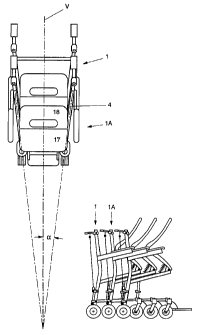
Fig. 1 and 2 show in side and top plan view an
individual wheelchair 1 according to the invention, in unused
condition. The wheelchair 1 comprises a frame 2 and a sitting
support 3. The frame 2 is made up of two side parts 4,
carried by two rear wheels 5, which are not steerable, and
two steerable front wheels 6. All wheels have the same size.
Each side part 4 of the frame 2 comprises a lower,
first tube 7, extending approximately horizontally, an
intermediate, second tube 8, to some extent slanting upwards
in the direction of the front of the wheelchair 1, and a
third tube 9, extending approximately parallel to the second
tube 8, which forms an arm support and to that end is
provided with an armrest 10. The third tube is shorter than
the first 7 and second tube 8. The first 7 and second tube 8
are not mutually connected at the front. At the rear, the
first 7 and second tube 8 are mutually connected by a rear,
approximately vertical tube 12 which extends beyond the
height of the second tube 8 and the third tube 9 and is
provided at the upper end with a grip support 13. At a point
between the second 8 and the third tube 9, the rear tube 12
is provided with a bend 11, in such a manner that the upper
part of the rear tube slants backwards to some extent. The
grip support 13 will be further discussed hereinafter. The
third tube 9 with armrest 10 is carried by the rear tube 12.
Extending approximately vertically between the first 7 and
second tube 8, at some distance from the rear tube 12, is a
central tube 14, which substantially supports the second tube
CA 02250184 1998-09-25
WO 97/35536 PCT/NL97/00153
9
8 and hence the sitting support 3, as will be further
explained hereinafter.
Each side part 4 extends substantially in a vertical
plane. The two side parts 4 are mutually connected by a first
cross connection 15 adjacent the forward ends of the first
tube 7 and by a second cross connection 16 between the rear
tubes 12, at a height between the first 7 and the second tube
8. The frame 2 of the wheelchair 1 is not collapsible and has
such dimensions that it cannot, unless with great effort, be
transported in a normal passenger car. A 'normal passenger
car' is understood to include at least a sedan and a
hatchback model, and 'in the passenger car' is understood to
refer to a passenger car with the doors and any loading doors
closed.
The sitting support 3 is formed by a bucket seat, made
of plastic, comprising a seat 17 and a backrest 18 formed
integrally therewith, or at least fixedly attached thereto.
On its underside, at the front thereof, the seat 17 is
hingedly connected to the forward ends 20 of the second tubes
8 via two hinge points 19. As a result, the seat support 3
can be swiveled forwards. In Fig. 1 the sitting support in a
forwardly swiveled position is represented in solid, full
lines, while the sitting support in the service position is
represented in broken lines. Arranged under the sitting
support 3 is a supporting frame 21. This supporting frame 21
is provided, adjacent the rear of the sitting support 3, with
a cross-rod 21A, which extends beyond the sides of the seat
17 and can abut against the upper side of the second tubes 8,
for supporting the sitting support 3 in the service position.
At the underside, between the second tubes 8 of the two frame
parts 4 and at some distance from the forward ends 20, a
third cross connection 22 is provided. Included between the
supporting frame 21 and the third cross connection 22 is a
spring device 23 which biases the sitting support 3 in the
forwardly swiveled position. In unloaded condition the
sitting support 3 is therefore always in the forwardly tilted
CA 02250184 1998-09-25
WO 97/35536 PCT/NL97/00153
position. Additionally, between the supporting frame 21 and
the third cross connection 22 a cable or chain 24 is
included, which has a length such that the sitting support 3
cannot swivel further than the forwardly tilted position
5 shown in Fig. 1. Obviously, the resilient means and the means
limiting the swiveling movement can also be constructed in
other ways.
Arranged at the front of the first tubes 7 are two
footrests 25. Included behind the rear tubes 12 is a brake
10 rod 26, which is connected at the top with a grip 28 via a
first swivel bearing 27, which grip 28 is connected with the
grip support 13 described earlier via a second swivel bearing
29. The first swivel bearing 27 is spaced from the second
swivel bearing 29, so that upon a tilting movement of the
grip 28 in approximately the vertical plane, the brake rod 26
is likewise moved in vertical direction. The lower end of the
brake rod 26 is pivotally connected with a brake bracket 30,
which is movable in the longitudinal direction parallel to
the rear tube 12 under the influence of the aforementioned
movement of the brake rod 26 in the vertical plane. At the
underside of the brake bracket a brake block 31 is included,
extending outwards at right angles to the longitudinal
direction of the brake bracket 30. The brake bracket 30, and
hence the brake block 31, is biased in downward direction by
a spring element, not shown in the drawing, for instance a
torsion or compression spring. Guide brackets 32 ensure that
the brake bracket 30 always moves along the rear side of the
rear tube 12. In a rest position, the brake block 31, owing
to the downward bias thereof, is pressed against the tread of
a rear wheel 5. As a result, the wheelchair 1 is braked. A
brake assembly as described above can, for trat matter, be
arranged on one as well as on both sides of the wheelchair 1.
If the wheelchair 1 is to be moved, for instance when a user
has sat down on the sitting support, the or each grip is
swiveled upwards, so that the brake rod 26 is moved up along
with it. The resultant vertical, upwardly directed movement
CA 02250184 1998-09-25
WO 97/35536 PCT/NL97/00153
11
of the or each brake bracket 30 draws the or each brake block
31 off the wheel 5 in question, so that the wheelchair can be
moved. If the or each grip 28 is released, the wheelchair 1
is braked again.
A wheelchair 1 as described in the foregoing is
nestable with a similar wheelchair 1, as represented in
Fig. 3. To that end, a wheelchair 1 is wheeled, with its
front first, from behind into the space between the frame
parts 4 of a preceding wheelchair 1A, with the sitting
support 3 of at least the preceding wheelchair 1A in unloaded
condition. In order to enable the rearmost wheelchair 1 to be
wheeled in, the two frame parts 4 of the wheelchairs 1, 1A
are arranged at an angle a relative to the longitudinal
median plane V of the wheelchairs. Accordingly, the vertical
projection of the wheelchair 1 is trapezoidal or wedged, with
the short side of the trapezoid directed forwards. The angle
a is so chosen that the rearmost wheelchair 1 can be moved
over approximately two-thirds of its length between the frame
parts 4 of the preceding wheelchair 1A, the front wheels 6 of
the rearmost wheelchair 1 then almost touching the front
wheels 6 of the preceding wheelchair 1A. The front wheels of
both the preceding wheelchair 1A and the rearmost wheelchair
1 therefore remain capable of swiveling. The angle which the
third tube 9 includes with the horizontal is then chosen such
that the armrest of a preceding wheelchair 1A can extend
simply and freely under the third tube 9 of the rearmost
wheelchair 1.
In order to prevent the wheelchairs 1, 1A being moved
too far under and into each other and thereby sustaining
damage, a stop tube 33 extending approximately horizontally
and parallel to the longitudinal median plane V is arranged
adjacent the lower end of at least one rear tube 12. This
stop tube 33 has a length approximately corresponding with
the length of the wheelchair, less the length over which the
wheelchairs 1, 1A can be moved into and under each other,
that is, are nestable. At the front the stop tube 33 is
CA 02250184 1998-09-25
WO 97/35536 PCT/NL97/00153
12
preferably provided with a plastic or rubber stop boss 34. In
the nested condition of the wheelchairs 1, 1A, the stop boss
34 abuts against, for instance, the rear side of the lower
end of the rear tube I2 of a preceding wheelchair 1A. The
wheelchairs 1, 1A then preferably do not make any further
contact with each other.
As is clear from the drawing and the description, the
wheelchairs in the nested condition occupy much less space,
in particular floor space, than in unnested condition.
Depending on inter alia the size of the wheels and the
relative position thereof, this saving can be, for instance,
10%, with the distance over which the wheelchairs 1, 1A can
be moved into and under each other being approximately 200 of
the length of the wheelchairs. The saving can also be, for
instance, 40%, with the wheelchairs being adapted to be moved
into or under each other over a distance amounting to 800 of
the length of the wheelchairs. In selecting the dimensions
and the extent of nestability of the wheelchairs, a suitable
compromise between riding convenience and nestability can be
opted for, for instance through an appropriate choice of the
wheel size.
As will be clear from Fig. 3 in particular, the
necessary space for nesting the wheelchairs 1 is provided by,
on the one hand, the trapezoidal shape of the wheelchair in
top plan view and, on the other, by the sitting supports
swiveling forwards in unloaded condition. The sitting support
3 being biased into the forwardly swiveled position moreover
provides the advantage that during use of the wheelchair, in
particular also during at least a part of the movement of a
user sitting down in or getting up from the wheelchair, the
user is optimally supported. Indeed, when getting up from the
wheelchair, the user will be supported to some extent in his
or her movement, and conversely, when sitting down, the user
will be braked to some extent, so that he or she will not
fall into the sitting support. Between the sitting support 3
in the service position and the frame 2, such an amount of
CA 02250184 1998-09-25
WO 97/35536 PCT/NL97/00l53
13
space is left-clear on all sides that a user or attendant
when using the wheelchair 1 cannot have his or her fingers or
other parts of the body caught in a painful manner.
In order to ensure that the wheelchairs 1 remain
mobile also in nested condition, provisions have been made
for centrally setting the nested wheelchairs "off the brake".
That is to say that through releasing operation of the
braking means of one of the wheelchairs, being the rearmost
wheelchair 1 in the example shown, all wheelchairs are
mobile. These provisions are built up, for instance, as
follows.
The brake bracket 30 is provided with a run-on pin 35
extending inwards, at right angles to the longitudinal
direction of the adjacent rear tube 12. Attached to the
central tube 14 is a run-on cam 36, of which an upper edge 37
slopes down in forward direction. During the nesting of the
wheelchairs 1, 1A, the run-on cam 36 of the rearmost
wheelchair 1 butts, through its upper edge 37, against the
underside of the run-on pin 35 of the preceding wheelchair
1A, where the or each brake block 31 bears on a rear wheel 5.
Upon further forward movement of the rearmost wheelchair 1,
the run-on pin 35 is moved up along the upper edge 37 of the
run-on cam 36, while carrying along the or each brake bracket
and hence the or each brake block 31. As a result, when
25 placing a wheelchair behind another wheelchair, the preceding
wheelchair is set "off the brake". In this manner it is
ensured that at least during the forward movement of the
wheelchairs, by pressing on the rearmost one, the preceding
wheelchairs are always "off the brake", and hence are
30 displaceable along with the rearmost one. Obviously, all
kinds of other provisions can be made for centrally setting
the wheelchairs off the brake in a nested condition.
In an alternative embodiment, not shown, during the
nesting of the wheelchairs, a preceding wheelchair 1A is
lifted somewhat at the rear side thereof by the next
wheelchair 1 being nested, in such a manner that the rear
CA 02250184 1998-09-25
WO 97/35536 PCT/NL97/00153
14
wheels of the former are lifted off the ground. As a
consequence, the brake blocks need not be dislodged from the
wheels, except in the rearmost wheelchair. This lift of the
rear side of the wheelchair can be obtained, for instance, by
run-on cams, for instance at the front of the stop tubes 33.
The rear tube 12, the central tube 14, the first tube
7 and the second tube 8 enclose a rectangle, which is closed
by a board 38. This board can be used, for instance, for
advertising purposes or it could indicate the origin and
other identification means.
Figs. 4 and 5 show in side and top plan view an
alternative embodiment of a wheelchair according to the
invention. Insofar as the wheelchair is the same as the
wheelchair described earlier, the same reference numerals
will be used, increased by a hundred, and for a better
understanding reference is made to the description given
earlier.
In a wheelchair 101 in this embodiment the sitting
support 103 is fixedly mounted on the frame 102, for instance
via the supporting frame 121. The frame 102 is the same as
the frame 2 of the wheelchair 1 described earlier.
The sitting support 103 comprises a seat 117 and a
backrest 118 mounted independently thereof, fitted, for
instance, against the rear tubes 112. Between the seat 117
and the lower edge 143 of the backrest 118 an opening 140 is
left clear, with a purpose to be further described
hereinafter. The seat 117 slopes down in rearward direction,
in such a manner that the underside of the front edge 141 of
the seat 117 is situated a distance D higher than the upper
side of the rear edge 142 of the seat 117. The lower edge 143
of the backrest 118 is situated higher than the upper side of
the front edge 141 of the seat 117. The width of the opening
140 is greater than the width of at least the front portion
of the seat 117.
When nesting the wheelchairs 101, lOlA, as shown in
Fig. 6, the front portion of the seat 117 of the rear
CA 02250184 1998-09-25
WO 97/35536 PCT/NL97/00153
wheelchair 101 is moved through the opening 140 in the
sitting support 103 of the front wheelchair 101A, above the
- seat 117 thereof. As a consequence of the suitably chosen
inclination of the seats 117, the underside of the front edge
5 141 of the seat 117 of the rear wheelchair 101 remains clear
of the seat 117 of the front wheelchair lOlA, while the
wheelchairs are yet nestable to a relatively large extent.
The angle of the seat and the thickness of the seat and the
supporting frame arranged thereunder can be chosen such that
10 a high degree of nestability i's obtained, while yet a
comfortable sitting support is maintained. Such a fixed
sitting support 103 provides constructional advantages over a
movable sitting support.
Fig. 7 shows a series of nested wheelchairs 201, 201A
15 according to the invention, in an alternative, advantageous
embodiment. In this embodiment the backrest 218 of the
wheelchair is fixedly connected to the frame 204, in
particular the rear tubes 212 thereof, while the seat 217 is
foldable into an approximately vertical position, in such a
manner that the seat 217 and the backrest 218 are
approximately in mutual abutment. To that end, the seat 217
is connected at the rear side witl-1 the frame 204 via a swivel
pin 219 which extends horizontally at right angles to the
direction of travel of the wheelchair 201. The swivel pin 219
is biased into a position such that the seat 217 in unloaded
condition is urged into the upwardly folded position. To that
end, for instance a torsion spring, not shown, is arranged.
Additionally, the swivel pin 219 is so designed that the seat
is at least substantially carried by it in both loaded and
unloaded position. Owing to the swivel pin 229 being arranged
adjacent the rear side of the seat 217, the second tubes 208
can be made of relatively short design, for instance up to
the upper side of the central tube 214. This central tube 214
then has no or substantially no bearing function and is
substantially intended for carrying the run-on cam 236 and
optionally for enclosing the board 238.
CA 02250184 1998-09-25
WO 97/35536 PCT/NL97/00153
16
If the-swivel pin 219 has sufficient bearing force to
independently bear the seat 217, the central tube can be
omitted entirely or partly, and the run-on cam 236 can be
arranged at a different position, for instance on the rear
tubes 212. Moreover, it is obvious that a mechanism for
setting the wheelchairs jointly "off the brake" can be
applied in a different manner. The wheelchair 201 in this
embodiment has the advantage that a particularly simple
construction is obtained with a particularly high degree of
nestability. The limiting factor of this nestability is then
formed only by the size of the (rear) wheels and/or the
thickness of the seat. Thus, such a wheelchair, when using
wheels with a diameter of 20 cm, can be simply designed in
such a manner that in the nested condition the rear
wheelchair 201 projects rearwardly from the front wheelchair
201A by, for instance, 20 cm. Thus five wheelchairs can be
nested on a floor area of a length approximately equal to one
meter plus the length of three front wheels in line; 140 cm.
A loose wheelchair then has a length of about 60 cm, which
means that a row of five loose wheelchairs would occupy a
length of about 300 cm. Moreover, for a wheelchair according
to the invention, substantially standard parts can be used.
At the rear, the wheelchair can be provided with an
inclining part, not belonging to the seat, against which the
front edge of the seat of the rear wheelchair butts during
nesting, in such a manner that the seat is automatically
urged in the upwardly swiveled position. In such an
embodiment the biasing spring can be omitted or at least be
designed to be less strong. The seat, upon unnesting of the
wheelchairs, falls back into the service position under the
influence of gravity.
Obviously, the seat can also be adapted to be swung
clear in other directions, for instance about a swivel pin
located along the front edge, similar to the swivel pin 19 in
Fig. 1, or about a swivel pin adjacent the middle or along a
CA 02250184 1998-09-25
WO 97!35536 PCT/NL97/00153
17
side of the seat. Further, for moving the seat, four-bar
mechanisms can be used.
In the foregoing, a frame 3, 103 has been described,
with the two frame parts 4, 104 in a fixed position relative
to each other. It is also possible, however, to adapt the two
frame parts 4, 104 for some degree of swiveling movement, in
such a manner that in a service position they extend
approximately parallel to each other and to the longitudinal
median plane, while in a nested condition the trapezoidal
shape is assumed. Here the swiveling movement of the sitting
support towards the forwardly tilted position can be
initialized by the movements of the frame parts 4. In such
an embodiment, during normal use a relatively compact frame
construction is obtained, with a rectangular basic shape,
while the wheelchairs are yet nestable.
Figs. 8-10 show a fourth embodiment of a nestable
wheelchair according to the invention, separately and in
nested condition. In this embodiment, which to some extent is
similar to a wheelchair according to Fig. 4 in particular,
the wheelchair 301 comprises a cross frame 302, a sitting
support 303 and a backrest 318. The cross frame 302
comprises, on opposite sides of the seat 303 and the backrest
318, a first frame tube 307, which extends from a fixed front
wheel 306 as far as a push rod 328 connecting the two first
frame tubes 307 at the top thereof. The cross frame 302
further comprises, likewise on opposite sides of the seat 303
and the backrest 318, a second frame tube 308, which extends
from a steered rear wheel 305 as far as an armrest 310 fitted
on the upper side of the corresponding second frame tube 308.
The seat 303 is carried by the first frame tube 307 and the
second frame tube 308 at an inclination a., in such a manner
that the front edge of a wheelchair 301 as shown in Fig. 10
can be moved above the sitting surface of the seat 303 of a
preceding wheelchair 301, while the armrest 310 of the
wheelchair extends partly above the armrest 310 of the
preceding wheelchair and the front wheels 306 of the
CA 02250184 1998-09-25
WO 97/35536 PCT/NL97/00153
18
wheelchair are accommodated under the seat 303 of the
preceding wheelchair and to that end have been moved between
and past the rear wheels of the preceding wheelchair.
The two non-steerable front wheels 306 are mutually
connected through a footrest 325 which is integrated with two
mudguard-like parts 325a which screen the side of the front
wheels 306 proximal to the user's feet during use. The push
bar 328 connecting the upper ends of the first frame tubes
307 has been shifted slightly towards the rear relative to
the backrest 318. Extending along the push bar 328 is a brake
handle 350 which is pivotally connected to the upper ends of
the first frame tubes 307. Through the first frame tubes 307
extends a brake cable from the brake handle 350 as far as
braking means, not shown in the drawing, arranged adjacent
the front wheels 306. Accordingly, by tilting the brake rod
350 the front wheels 306 can be braked and be released.
Extending rearwards from the rear edge of the seat 303
is a lift knob 351, which is so located that when a
wheelchair 301 is being nested from the rear into a preceding
wheelchair 301, the underside of the seat rises along the
lift knob 351, whereby the lift knob 351, in the nested
condition, is partly received in a recess 352 provided under
the seat 303 and the front wheels 306 of the rear wheelchair
301 are lifted slightly off the floor. As a result, the
wheelchairs can be moved together, also when the front wheels
of rear wheelchairs are braked.
A wheelchair 301 according to Figs. 8-10 has the
advantage that it is simple to manufacture, has an attractive
appearance, exhibits good maneuverability and moreover is
safe in use. Viewed in side elevation, the braked front
wheels 306 are located forward of the front edge of the seat
303. Owing to the footrest 325 being included between the
non-steered front wheels 306, a user can bring to bear at
least a part of his weight on the footrest 325 without the
wheelchair thereby tilting, even when the user will stand up
substantially straight. This means that stepping into and out
CA 02250184 1998-09-25
WO 97/35536 PCT/NL97/00153
19
of the wheelchair does not entail the risk of the user
falling over along with the wheelchair. Obviously, such an
arrangement of the footrest can also be opted for with other
wheelchairs according to the invention. In addition, in the
other embodiments too, it is possible for the front wheels to
be of non-steerable design and for the rear wheels to be of
steerable design, and furthermore all wheels can be made of
steerable design.
By way of illustration, a number of measurements of a
nestable wheelchair according to the invention are given,
which measurements should not interpreted as being
limitative. A wheelchair according to Fig. 8, for instance,
has a wheelbase of 510 mm, a seat height of 530 mm at the
front edge and 460 mm at the rear edge, the inclination of
the seat being about 10° on average. The backrest has a lower
edge at 540 mm from the ground and an upper edge at about 900
mm from the ground. The distance between the axles of the
rear wheels of two mutually nested wheelchairs is about 230
mm, while the front and rear wheels have a diameter of about
200 mm. This means that two unnested wheelchairs arranged one
behind the other occupy a floor area approximately 1420 mm in
length, while the same wheelchairs in nested condition occupy
a floor length of about 940 mm, a saving of about 300. The
use of smaller wheels and a greater inclination and/or lesser
thickness of the seat can lead to a greater saving on the
floor area needed.
Obviously, where desired, features described earlier
can be used in a wheelchair according to Figs. 8-10.
In an advantageous embodiment, at least a number of
wheelchairs are designed in sizes for pre-school children,
infants or possibly babies. This is advantageous in
particular when they are used in department stores and the
like. Such wheelchairs can be hired out or lent out as
buggies, so that people with little children are not
dependent on buggies and the like which they have brought
along, while the personnel need not collapse and unfold the
CA 02250184 1998-09-25
WO 97/35536 PCT/NL97/00153
buggies every-time. Such wheelchair buggies according to the
invention are therefore more robust and handier in use.
An assembly of a series of wheelchairs according to
the invention can be used as follows, assuming, by way of
5 example, the context of a hospital.
A patient arrives at a hospital hall, where a series
of wheelchairs are arranged in nested condition near the
entrance. The rearmost wheelchair i, 101 is moved backwards
from the row by an attendant by gripping and moving up the
10 grips 28, 128, while simultaneously wheeling the wheelchair
1, 101 backwards. Then the patient can sit down on the
sitting support, whereby, at least in the wheelchairs shown
in Figs. 1-3, the sitting support 3, 103 is urged to the
service position. Having arrived at a destination, at any
15 rate after use, the wheelchair 1, 101 can be left behind, for
use by others. In the inoperative position the wheelchair is
automatically braked. At the end of the day, or so much
earlier as desired, a person appointed for that purpose can
collect the various wheelchairs which have become spread
20 through the hospital, and return them to the arrangement
point near the entrance. To that end, each time he or she
finds a wheelch;~ir unattended, he or she can nest it in the
series of wheelchairs already collected, the collector only
needing to operate the braking means of the rearmost
wheelchair for him to bring the entire series of wheelchairs
in nested condition back to the entrance, ready for
subsequent use, without any assistance from others. Owing to
the wheelchairs being uncollapsible, they cannot be readily
carried off by the users. For that matter, anti-theft
attachments such as alarm devices and the like can be
included, as can locking means preventing use. The
wheelchairs according to the invention therefore have the
advantage that they occupy little space in a storage position
and yet are convenient in use, notably in that they need not
be set up or unfolded for use, while moreover collecting the
CA 02250184 1998-09-25
WO 97/35536 PCT/NL97/00153
21
wheelchairs can be carried out fast and efficiently by a
single person.
When using an assembly in places where the wheelchairs
are also intended for outside use, as for instance at
airports and railway stations or nursing homes, hospitals or
rehabilitation institutions with an outdoor space such as a
garden or parking lot, it is preferred that means are
provided for the covered and optionally secured arrangement
of the wheelchairs, an embodiment with a tiltable sitting
support moreover enjoying the advantage that it prevents
precipitation being left on the seat. In a wheelchair
according to the invention, it may be an advantage for the
wheelchair to have an appearance that is little attractive,
in any case for private use, since this considerably reduces
the risk of such a wheelchair being stolen.
Obviously, the other wheelchairs shown and other
wheelchairs according to the invention can be used in a
similar manner.
Analogously to the foregoing description, an assembly
of wheelchairs can also be designed for nesting from the
front. In that case, the wedge shape shown can be mirrored
with respect to a plane at right angles to the direction of
travel, in such a manner that the wheelchair has the largest
width at the front. The seat can then be adapted, for
instance, to swing clear in rearward direction, optionally as
shown in Fig. 7, and with a footrest capable of swinging
clear.
The invention is not in any way limited to the
embodiments shown in the drawings and described in the
description. Many variations thereof are possible.
Thus, for instance, only three wheels may be provided,
and the frame may be built up differently, for instance
wholly or partly from plate elements or the like. Obviously,
other sitting supports can be used, in which case the entire
sitting support or a portion thereof can be differently
designed to swing clear or be removable. The seat can be
CA 02250184 1998-09-25
WO 97/35536 PCTlNL97/00153
22
adapted to swing clear forwardly or laterally, while the
backrest may or may not be fixedly arranged. Further, the
wheelchairs can be so designed that the wheelchairs described
in the foregoing can be combined into one assembly of
nestable wheelchairs. Obviously, the wheelchairs, in addition
to being nestable, can also be wholly or partly collapsible
or detachable, while moreover all kinds of accessories can be
arranged, such as a headrest or neck support, driving means
and the like. The braking means can be designed differently,
for instance as rim or drum brakes. Further, the bias of the
sitting support of the wheelchair into the forwardly swiveled
position can be obtained differently or be omitted.
These and many similar adaptations and variations are
understood to fall within the scope of the invention.
CA 02250184 1998-09-25