Note: Descriptions are shown in the official language in which they were submitted.
CA 022~02~7 1999-01-07
METHOD FOR DIGITAL TRANSMISSION OF INFOR~ATION
Description
The invention relates to a method for digital
transmission of data over copper lines, wherein digital
signals are precoded with a fixed precoder on the transmitter
side and wherein the signals are recovered on the receiver
side through blind equalization ~see "IEEE Journal on Selected
Areas in Communication", Vol. SAC-13, December 1995, pp. 1622
to 1633).
This method can be used for transmission of information
over copper lines as well as for wireless transmission. The
subsequent discussion relates mainly to applications for
transmission over copper lines and is in no way intended limit
of the applicability of the invention.
Fast digital transmission methods over copper cable, that
include several or a large number of so-called two-wire lines
placed next to each other, have become increasingly important
because of their potential to enable a variety of new digital
services in the near future. They also provide a gradual
transition to glass fiber networks and have to be able to
operate reliably over long cable lengths, because the number
of repeaters between the telephone exchange of a telephone
network and the subscriber has to be kept small for economic
reasons.
Attenuation and distortion ~uring the land-line
transmission of in~orma~ion signals produce channèl-related
inter-symbol interference (ISI). The channel-related ISI in
digital information transmission can be effectively eliminated
CA 022~02~7 1999-01-07
through equalization with decision feedback equalization
(DFE). This method is highly efficient and not very complex.
However, DFE cannot be combined directly with coded modulation
because the feedback filters in DFE require an immediate
decision about the transmitted signals.
Tomlinson (see Electronics Letters, Vol. 7, March 1971,
pp. 138 and 139) and Harashima/Miyakawa (see IEEE Transactions
on Communications, Vol. COM-20, August 1972, pp. 774 to 780)
propose a solution for this problem. They propose to shift
the feedback filter of the DFE to the transmitter. In
addition, they introduce a modulo operation to limit the
amplitude. This method is referred to as Tomlinson-Harashima
precoding (THP). However, a transmission with optimal THP
requires information about the channel state on the
transmitter side which has to be transmitted via a return
channel. This requires complex protocols for setting up the
connection to prevent mutual blocking of the two transmission
directions. Also, not every application may have a return
channel.
This problem can be sidestepped, as described in the
above referenced article, by employing a fixed precoder which
simplifies the set-up of the connection. However, precoding
that is not optimized produces residual interference which has
to be equalized linearly on the receiver side. The linear
equalizer for the residual interference is adapted blindly,
i.e. without using a training sequence. However, in a system
using THP, it is essentially impossible to provide blind
equalization at the symbol clock rate because the signal that
CA 022~02~7 1999-01-07
has to be reconstructed has an approximately discrete Gaussian
distribution. The precoding is therefore modified to limit
the dynamic range of the effective transmitted signal and to
produce signals with better statistics. An example for such a
S method is "Dynamics Shaping" (DS). The DS method permits
blind equalization while maintaining or even increasing the
excellent efficiency of THP. For uncoded transmission with
the DS method, a simple standard method for blind equalization
can be employed, using the so-called Sato algorithm (see IEEE
lo Transactions on Communications, Vol. COM-23, June 1975, pp.
679 to 682).
It is the object of the invention to improve the method
described above and also the blind equalization process.
The invention solves the object by subdividing the blind
equalization into an equalization of the magnitude followed by
an equalization of the phase.
This method for digital data transmission is easy to
implement. Most importantly, the signal which is to be
recovered in the equalizer may be correlated, whereas the
methods known in the art can only recover white signals. The
method is very efficient due to the fixed precoding and two-
stage blind equalization. The precoding is adapted to a fixed
reference application, so that channel information does not
have to be retransmitted. Blind equalization removes the
resulting residual interference. Equalization of the
magnitude takes into consideration any correlation present in
the transmitted sequence. The blind equalization can then be
robust even if the signal-to-interference ratio at the
CA 022~02~7 1999-01-07
equalizer input is very small. In particular, after the
magnitude has been equalized, a simple blind algorithm can be
used to equalize the phase. The convergence is very fast, in
spite of strong residual interference at the input of the
S magnitude equalizer, and in spite of a low signal-to-noise
ratio (SNR) and the presence of correlated symbols that have
to be reconstructed.
The cable path that can be spanned can be significantly
lengthened by further coding of the signals, for example by
using trellis-coding. In this case, equalizing the magnitude
before separately equalizing the phase has also proven to be
particularly advantageous due to the small signal-to-noise
ratio at the equallzer input.
The method of the convention will now be described with
reference to an exemplary embodiment and the accompanying
drawings.
It is shown in:
Figure 1 is a block diagram of a copper line transmission
path that is the subject matter of the present invention,
Figure 2 is block diagram of an addition to that shown in
Figure 1, and
Figure 3 is block diagram of an additional embodiment
that is the subject matter of the present invention.
The method of the convention will now be described with
reference to an exemplary embodiment and the accompanying
drawing.
The following description is based on a digital
transmission of signals and data, respectively, in the base
CA 022~02~7 1999-01-07
band. Consequently; all signals and systems have real values.
The method is also described for the case where the signals
are first encoded, preferably trellis-coded. However, the
invention does not require additional encoding.
As seen in Figure 1, the binary data is first encoded by
a channel coder, which generates a series of Pulse Amplitude
Modulation (PAM) symbols a[k] ~ {+1, +3, ..., +(M-1)}, each
symbol may assume M values. Precoding with dynamic limitation
maps the series a[k] to a series x[k] of channel symbols. The
series x[k] is applied to a transmit filter GT(f) and
transmitted via a two-wire line of a copper cable with a
length l and a transfer function HK(f, l). A Gaussian
interference nO(t) is assumed to be present in the transmission
path. For transmission via HDSL (High Rate Digital Subscriber
Lines), such interference can be, for example, near-end
crosstalk originating from a number of other HDSL systems
which transmit over two-wire lines running in parallel in the
same cable.
The input filter of the receiver is an optimized Nyquist
filter (ONF) HR(f, lo) which without THP would generate on the
receiver side an ISI-free signal after sampling with the
symbol clock rate, as long as the actual cable length matches
the design length lo which was postulated when the precoder and
the input filter were designed. The case l = lo produces
residual interferences. All parameters of the actual
conditions and the reference application, except the cable
length l, are assumed to be identical. This is not a
significant limitation because differences in other parameters
CA 022~02~7 1999-01-07
can be adequately expressed as equivalent differences in
length.
The linear equalization provided by the ONF produces
strong colored noise with a very high variance in the sampled
signal. The noise can be reduced by connecting a subsequent
FIR filter H(z) that converts the noise into approximately
white noise (noise whitening filter). The coefficients of
this monic (i.e. linear) minimum-phase filter can be
calculated with the help of the Yule-Walker equations by
requiring that the noise variance at filter output is minimum.
(The term "monic" being defined as, for a polynomial, having
the coefficient of the term of highest degree equal to 1, or
in other words "linear".) The transmitter coupling in a cable
transmission can be taken into account by requiring a zero of
H(z) at DC (z = 1) (DC = Direct Current).
The filter H(z), the output signal of which is referred
to as r[k], generates again ISI which has to be removed by the
fixed precoder. With THP, the series x[k] of channel symbols
is generated sequentially symbol-by-symbol according to the
following equation:
(~h
x[k] = a[k] + 2M * d[k] - ~h[K] * x[k - K] .
The symbols d[k] ~ Z here correspond to the modulo-
operation in THP. The sequence h[~] indicates the impulse
response of the noise whitening filter of degree qh.
CA 022~;02~;7 1999-01-07
For the following process, an effective data sequence
(EDS) vtk] is defined via the following equation:
v[k] = a[k] + 2M * d[k].
The series x[k] is produced by filtering v[k] with the
formal inverse of H(z). Consequently, the EDS arises again
after the filter H(z), if no is present and l = lo~ The series
a[k] of PAM symbols can then be unambiguously recovered by
applying once again a modulo-operation.
Precoding can also be modified to produce signals with a
more advantageous statistics. For example, the DS method can
be used, which enables a blind equalization; additionally the
already high efficiency of THP can be further increased. With
the DS method, the series d[k] is not selected symbol-by-
symbol, but by measuring symbols over a longer period of time,
with the requirement that the transmitted power is minimum.
The boundary condition ~v[k]l < V~x has to be observed. The
variable V~AX is the externally prescribed maximum amplitude of
EDS .
As can be seen rom the power density spectrum ( PDS ) of
Zo the EDS~ the temporally adjacent values are strongly
correlated with THP as well as with the DS method. This
correlation, as well as the large number of possible levels of
the EDS values - even when using the DS method - and a low SNR
at the equalizer input, put severe demands on the blind
equalization on the receiver side. The residual interference
is removed by a linear equalizer which reconstructs the EDS
CA 022~02~7 1999-01-07
v[k] and is adapted without a training sequence, i.e. blindly.
The equalizer cannot directly reconstruct the series a~k] due
to the nonlinear modulo-operation in the pre~oder.
The blind equalization is subdivided into an equalization
of the magnitude followed by an equalization of the phase.
This improves the performance of the blind equalization over a
single stage structure. A corresponding structure is shown in
Figure 2. The transfer function F(z) represents a prediction
filter, D(z) is a coloring filter and the function G(z)
represents a phase equalizing filter.
When the magnitude is equalized in a conventional manner
by using conventional technique, an approximately white signal
with minimal variance is forced at the output of the magnitude
equalizer. A white output signal of the magnitude equalizer
can remove distortions of the magnitude only if the
transmission sequence has also a constant PDS. If this is not
the case, then the magnitude equalization has to be modified
so as to produce a variable PDS of the signal to be
reconstructed. This can be accomplished with the two methods
described below. The first method produces a white signal as
an intermediate signal which is subsequently filtered in a
suitable manner. The second method directly assigns the
desired PDS and the autocorrelation sequence (ACS),
respectively. Both methods are designed for correlated
transmission signals.
Embodiment of the Magnitude Equalization
An approximately white signal is produced with a
CA 022~02~7 1999-01-07
prediction error filter 1 - F(z) configured as an FIR filter
of degree q,. The white signal is then colored with a fixed FIR
filter D(z) to produce a good approximation of the PDS of the
EDS at the output of the FIR filter. The predictor
coefficients f [k] can be adjusted using either a Least Mean
Square (LMS) algorithm or a Recursive Least Squares (RLS)
algorithm. Most importantly, the power of the output signal
of the prediction error filter has to be minimized. If a fast
convergence of the first stage is desired, then the RLS
algorithm should be selected.
The coloring narrow-band filter D(z) is calculated by
solving the Yule-Walker equations to produce a fictitious
prediction-error filter 1-W(z) for the EDS with a relatively
high degree qw. In the absence of noise or ISI, and if q~ =
qf, the calculated coefficients are identical to those in the
filter l-F(z) after adaptation is complete.
The fictitious filter 1 - W(z) would generate from the
EDS an approximately white sequence. The inverse system 1/(1
- W(z)) can be used as a coloring filter D(z). Because the
fictitious filter 1 - W(z) is a minimum-phase and monic
filter, which is generally the case for prediction error
filters calculated with the Yule-Walker equations, this
inverse system can also be approximated by a causal, minimum-
phase and monic FIR system. The Yule-Walker equations are
subsequently used a second time to calculate the coloring
filter D(z) which produces a signal with the highest possible
whiteness from a signal with an ACS which is the same as the
filter ACS of 1 - W(z). The coloring filter D(z) depends only
CA 022~02~7 1999-01-07
on the fixed pre-selected precoder and can therefore be
calculated and set to fixed coefficient values.
lhe method described above guarantees a minimum-phase
filter D(z). Since the prediction error filter 1 - F(z) is
also minimum-phase after convergence, the total transfer
function of the magnitude equalizer is also minimum-phase.
This aspect is advantageous for the subsequent phase
equalization. In the present application, the phase response
of the transfer function that is to be equalized, and
consequently also the phase response of the inverse system, is
closer to the phase response of a minimum-phase system than of
a maximum-phase system. The residual phase distortions that
remain after the magnitude has been equalized are then not too
severe. The magnitude can be completely equalized by applying
a correction with a factor SQUAREROOT('c[k]') subsequent to
the filter D(z), wherein the factor is adjusted adaptively to
make the powers of u[k] and v[k] identical. The signal u[k]
is here the output signal of the automatic gain control (AGC).
Embodiment of the Magnitude Equalization
The magnitude is equalized with a single filter. The
coefficients of the filter are adaptively adjusted to produce
the desired ACS of the EDS directly at the output of the
filter, except for an acceptable factor which can be removed
by the AGC. An algorithm for this purpose is described in the
2S following. The structure is assumed to be identical to that
of Figure 2, except that the coloring filter D(z) is omitted.
The (time dependent) coefficient vector for F(z), f[k] =
CA 022~02~7 1999-01-07
[fl[k] f2[k] fq[k]] T is recursively updated according to
f[k+1] = f~k] - ~f ('p[k] ,2 * ~ - p[k] * s[k]), wherein unlike
in the previous formula, the number of the coefficient appears
as an index.
The signal p[k~ is the output signal of 1 - F(z), s[k] is
a vector with the most recent qr output values, where s[k] =
[p[k-l] p[k-2] p[k-qf]]T, and ~ is a vector with the desired
(normalized) ACS values of the filter output signal,
pvv [1] ~pvv [2] ~Vv [ql]
I ~pvv [O] :pvv [()] ~pvv [O] ~
The equation fLk + 1] which applies to a base-band
transmission can be easily modified for a modulated
transmission, i.e. for complex signals. After convergence,
the first qf + 1 ACS values of p[k] and v[k] are identical,
except for a factor. The ACS sequences are then almost
perfectly matched, unless qr is too small. The remaining
factor can be corrected, as described above, by using AGC.
The magnitude is reliably equalized after the method has
converged. Despite the method employs a gradient descent, it
converges relativeiv fast when equalizing residual
interference. Unlike the situation described in the previous
section, the prediction error filter 1 - F(z) here has to
remove only the correlation produced by the channel, but not
the correlation inherent in the EDS.
CA 022~02~7 1999-01-07
'
After the magnitude is equalized, the phase is equalized
to remove the ISI which remains in the signal after the first
stage and which is mainly caused by phase distortions. The
method used here is truly blind and adapts another FIR filter
G(z). The second adaptation process is started only after the
first stage has converged. In this way, the second process is
not adversely affected by the first process. Advantageously,
the Sato algorithm is applied, more particularly a variation
of the Sato algorithm modified according to Benveniste, which
during the adaptation process produces a gradual transition to
the DDLMS algorithm, thereby reducing the power of the error
signal in the steady state.
Simulations have confirmed that, if the magnitude is
equalized first, then the phase equalization in the second
equalization stage converges even with a very small SNR
produced due to a long cable. The correlation in the EDS has
no adverse effect due to the drastically reduced ISI after the
first stage. The adaptation process continues after
convergence to track slow channel variations. On the other
hand, the coefficients used in the prediction filter F(z) to
equalize the magnitude can be held constant after the start of
the phase equalization process.
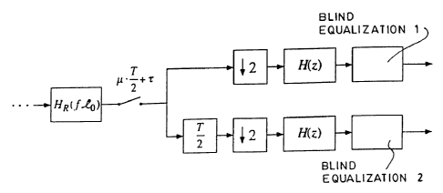
The receiver structure can be modified to make the method
less susceptible against erroneous sampling instants. This
can be achieved by using the receiver structure of Figure 3.
After the signal is sampled at the output of the ONF HR(f,
Io) at intervals T/2 with the sampling phase ~, the received
values are supplied alternatingly to two separate branches of
13
CA 022~02~7 1999-01-07
a filter bank for further processing. This produces two T-
spaced sub-channels with sampling phases which are offset
relative to each other by T/2. After equalization of each of
the two T-spaced subchannels with the respective optimized
linear equalizer, at least one of them has a location to
produce an almost maximum attainable SNR for an arbitrary
phase during the T/2 sampling. It is recommended to carry out
a separate blind equalization in each of the two channels. By
this, the convergence problems described in the published
prior art references the blind T/2-spaced equalization can be
eliminated. The method of separately equalizing the magnitude
and the phase is again applied to the sub-channels. After
convergence, the output signal of the better branch of the
filter bank is selected for the subsequent decoding. This can
be accomplished, for example, by comparing the temporally
averaged squared error signals of the two blind equalizer
algorithms in the sub-channels.