Note: Descriptions are shown in the official language in which they were submitted.
CA 022~0314 1998-10-14
FIELD OF THE INVENTION
The invention relates to snowboards, and in particular to a boot
mounting plate for mounting the operator's boots on the snowboard.
BACKGROUND OF THE INVENTION
Snowboards have achieved wide popularity. In general a snowboard
consists of a relatively wide flat board with a narrow waist and wider tip and
tail. Snowboards are usually wider than skis and shorter. The board has
two boot attachment means; these allow the operator to attach his
snowboard boots to the snowboard and operate it.
0 In the operation of a snowboard, to make turns from one side to the
other, it is intended that the board will flex on the surface of the snow
somewhat in the manner of the flexing of a ski, so as to make longer or
shorter radius turns.
However, since the snowboard itself is usually shorter than a ski, and
since the boot fastening devices are usually located spaced apart along the
length of the snowboard, it is apparent that the weight of the operator will
be applied to the board over a relatively long central area of the snowboard.
As a result, the snowboard will only be able to flex freely upwardly in front
of the front boot and behind the rear boot.
Between the two boots, the snowboard will generally not flex in the
desired manner and often remains flat. Occasionally, it may even flex in the
reverse direction.
CA 022~0314 1998-10-14
This detracts from the performance of the snowboard and can make it
somewhat unpredictable.
In order to overcome this, some snowboard operators deliberately tilt
their weight either forwards or backwards. In fact, it is common for the
operator to actually attempt to lift the front foot while putting weight on the
back foot or vice versa, so as to achieve a particular type of flex. This tends
to make snowboarding, at least in the more advance stages, difficult to learn
and somewhat unpredictable in performance.
For all of these reasons, it is desirable to provide a boot mounting
plate, which plate has a centrai attachment portion that can be attached mid-
way with respect to the length of the snowboard, and which is provided with
front and rear boot mounting portions which are raised above the snowboard,
so that the weight of the operator is transmitted through the plate center
portion to the central area of the board.
In this way, the board is capable of flexing over a much greater length.
This is an advantage for the snowboard operator.
BRIEF SUMMARY OF THE INVENTION
The invention seeks to achieve the foregoing and other advantages by
the provision of a boot mounting plate for a snowboard, comprised of, a
central mounting plate portion, having a predetermined length and width,
adapted to be attached to a mid point on the snowboard, a forward boot
portion which is forwardly upwardly angled relative to the central portion, for
CA 022~0314 1998-10-14
mounting of the forward boot, a rearward boot portion which is rearwardly
upwardly angled relative to the central portion for mounting the rearward
boot, and, resilient mounting means extending between the central portion of
the plate and the snowboard whereby the snowboard is permitted to flex
upwardly under the boots, and in a controlled manner between the flexible
mounting means.
The invention further provides for resilient biassing means connecting
the resilient mounting means to the board and plate, so as to provide for a
resilient movement of the board mounting plate relative to the board.
0 The invention further provides for biassing means located between theboard and the forward plate portion and between the board and the rearward
plate portion, for providing further resilient biassing.
The invention further contemplates the use of additional stiffening ribs,
for providing increased stiffness to the central portion of the snowboard.
The various features of novelty which characterize the invention are
pointed out with more particularity in the claims annexed to and forming a
part of this disclosure. For a better understanding of the invention, its
operating advantages and specific objects attained by its use, reference
should be made to the accompanying drawings and descriptive matter in
which there are illustrated and described preferred embodiments of the
invention .
CA 022~0314 1998-10-14
IN THE DRAWINGS
Figure 1 is an upper perspective illustration of a snowboard showing
the boot mounting plate attached thereto;
Figure 2 is a top plan illustration of the snowboard and boot mounting
plate Figure 1, with portions of the snowboard cut away;
Figure 3 is a side elevation of the central portion of the snowboard and
the boot mounting plate of Figure 2, and showing flexing movement of the
board in phantom;
Figure 4 is a section along the lines 4-4 as Figure 2, illustrating the
resilient mounting of the plate on the board under flexural loading;
Figure 5 is a side elevational view showing a further modification of
the invention;
Figure 6 is a top plan view of a further modification;
Figure 7 is a side elevational view of a further modification;
Figure 8 is a side elevational view of a further modification; and
Figure 9 is a side elevational view of a further modification.
DESCRIPTION OF A SPECIFIC EMBODIMENT
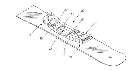
Figure 1, the invention will be seen to comprise a boot mounting plate
indicated generally as 10 shown mounted on a snowboard S. The
snowboard S may be any one of a wide variety of different shapes and sizes
of snowboards which may be used for various different purposes, and the
CA 022~0314 1998-10-14
illustration of the snowboard S in this particular set of drawings is without
limitations to any particular type of snowboard.
The boot mounting plate 10 will be seen to have a central board
attachment portion 12, a forward boot mounting portion 14 and rearward
boot mounting portion 16.
In this embodiment, the entire plate 10 is formed as a casting of
lightweight material, such as aluminum or a suitable alloy or composite
material, so as not to contribute substantially to the weight of the
snowboard .
n Plate 10 may be of hollow construction and may be provided with a
plurality of openings as shown in the drawings, the details of which are
omitted for the sake of clarity.
It will be noted from the drawings that while the central attachment
portion 12 of the plate 10 is flat, and coplanar with the center of the board
S, the forward boot attachment portion 14 is angled forwardly and upwardly
relative to the central portion 12, and the rearward boot attachment portion
16 is angled rearwardly and upwardly relative to the central portion 12 of the
plate 10.
Central portion 12 is, in this embodiment, attached to the board by
means of four mounting bolts 18, passing through suitable openings in the
central portion 12. The bolts 18 are recessed inside plate 10 through holes
in the top of the central section of plate 10 (Figure 4) indicated as 20.
CA 022~0314 1998-10-14
The board S in this embodiment is provided, by way of example only,
with recessed threaded fastenings 22, recessed into the underside of the
board S, and adapted to threadedly receive the bolts 18.
It will of course be appreciated that this is only one illustration of the
means of attachment to the board, and that various means of attachment to
the board may be used without limitation to the particular form shown.
The bolts 18 pass through the central portion 12 of the plate 10,
through oversized openings indicated as 24. They are cushioned on their
upper sides by resilient washers or disks 26. Resilient cushioning pads 28
0 are provided between the plate 10 and the board S.
Front boot bindings 30 and rear boot bindings 32 are mounted on
forward and rear portions 14 and 16 of plate 10.
In many cases, the degree of resilience or biassing achieved by the
washers and the pads, will provide sufficient resilience for the board
mounting plate to be operated at a satisfactory degree of effectiveness.
The operator simply applies his weight to the boots, and may bias
more or less weight to the front or rear boot as required. This weight
biassing transfers loading on plate 10 either forwardly or backwardly and
applies a corresponding biassing force to the points of attachment between
the board and the plate which in turn transfers loading towards the tip or tail
of the snowboard without causing the unequal dead spots between and
under the boot attachment means, which were often encountered when
CA 022~0314 1998-10-14
using conventional snowboards with conventional boot attachments directly
on the boards.
However, in order to achieve greater effects, it is possible that extra
resilient means such as springs 34 (Figures 3 and 5) may be attached
between the front and rear portions 14 and 16 of the plate 10 and the board.
This may have the effect of spreading the biassing effect of the movement of
the operators weight over a greater area of the board, achieving still further
improvements in performance.
Various modifications can be made in the design without departing
0 from the invention.
For example, while the drawings show a boot mounting plate which is
symmetrical fore and aft in terms of its length and angling upward from the
board, it is possible that an asymmetric design might be suitable for some
purposes, in which case there would be a rear mounting portion of the boot
mounting plate which might be longer and have greater of lesser upward
angling than the front mounting portion.
Another modification might be the spacing of the resilient pads 28.
These could be spaced somewhat further apart, or closer together, so as to
vary the stiffness of the central portion of the board. Pad position and
spacing might also be asymmetric from side to side. Additionally, the
tension of the screws 18 might be varied, so as to pretension discs 26 and
the pads 28.
CA 022~0314 1998-10-14
Springs might take the place of the discs 26 and the loading of said
springs and the pads 28 may all be adjustable as are springs 34 and 36 in
Figure 5, so as to provide varying degrees of stiffness to the board and may
conceivably provide for asymmetrical loading so as to provide greater
stiffness in one part of the board.
The use of an asymmetric cantilever plate or a cantilever plate in
which the loading on the pads and springs, and their positions, can be varied
is particularly advantageous when used in combination with snowboards,
which are themselves asymmetric. In this type of snowboard, the centre of
0 curvature of the snowboard's edges are asymmetrically located from back tofront, with one side's centre of curvature located ahead of the other side's.
With this type of board, it is necessary for the manufacturers to make them
either left foot forward or right foot forward, to accommodate left and right
handed operators. By the use of the cantilever plate the stiffness of the
board can be made asymmetric in the same sense as edge centre of
curvature, in either direction, without the requirement of a board which is leftor right handed. Asymmetric stiffness has a similar effect as asymmetric
centre of curvature.
It will also be appreciated that the boot mounting plate transfers the
downward force applied by the boots towards the centre of the board,
allowing the board to bend freely under the weight of the operator,
underneath the area of the boots and the binding. This is not possible with
CA 022~0314 1998-10-14
conventional snowboard binding setups, where the area under and between
the front and rear boot often takes on an undesirable flat or reverse
curvature. The curvature may also change in an undesirable manner as the
board flexes. This produces unpredictable and undesirable results. The
operator of a conventional board must maintain a form of "board bending"
action by raising the toe of the front boot and raising the heel of the rear
boot in an effort to force the board to assume a correct curvature,
particularly through the mid section between the front and rear boot
bindings. This can be extremely difficult to maintain during complex and
0 rapid manoeuvres with a snowboard, and it also restricts other desirable leg
movements .
With the boot mounting plate in accordance with the invention, these
requirements are avoided, since the board will adopt a substantially smooth,
natural curvature beneath the plate, leaving the legs free to guide and turn
the board as desired.
The use of the board mounting plate according to the invention
provides a more orthopaedically desirable alignment of the front and rear
boots and feet, so that the front toe is raised and the rear heel is raised.
This allows the operator's hips to be aligned perpendicularly to the board's
forward direction giving the operator a forward oriented stance.
This in turn enables the operator to use ski poles in exactly the same
manner as ski poles are used by a skier, providing for much greater
CA 022~0314 1998-10-14
manoeuvrability and ability to traverse rough terrain. It also permits the
operator to move around when he has reached the bottom of the hill, without
having to release the rear boot from the snowboard.
As best shown in Figure 6, the board may be provided with adjustable
stiffeners in the form of fibre-glass/carbon-fibre frames indicated generally as40, which may be in various different forms and may be formed of various
different composite materials. The stiffeners are fastened to the board S at
their centers with screw fasteners and may be provided with recesses 42 at
the ends of the arms, and additional screw fastenings 44 may be provided.
0 The screw fastenings 44 may be tightened up so as to make that portion of
the board substantially stiffer. Alternatively, the recesses 42 may be in the
form of slots, and the screws may be only partially tightened so that the
stiffeners allow a certain degree of softer flexing before the fastenings reach
the end of their slots.
If necessary, some form of resilient biassing can be incorporated in the
slots (not shown) such as springs or blocks of resilient material, so that the
effect of the stiffening is progressive, and controllable.
It should be clear that this arrangement allows each end of each
stiffener to be adjusted individually permitting any combination,
forward/backward and/or side to side of stiffening asymmetry.
Other forms of resilient connection can be made between the boot
mounting plate and the board, such as is shown in Figures 7 and 8. Figure 8
CA 022~0314 1998-10-14
shows a leaf spring mounting 50, and Figure 7 shows another form of
resilient pad 48.
As illustrated in Figure 9, a control linkage system could be used, to
provide additional control over torsional flexing and stiffness of the board,
the linkage being generally shown as 52. Although not shown in Figure 9,
the linkage 52 extends the full width of plate 10 which results in significant
torsional stiffening to the board S.
The use of the invention also enables the operator a much greater
degree of safety. In conventional snowboard binding systems there are no
0 safety releases similar to ski boot bindings.
However, using the boot mounting plate technology described herein it
would be relatively simple to incorporate spring-loaded boot and/or plate
releases similar to those used on conventional skis, so that the boots or the
entire plate would become released from the snowboard in the event of a
fall.
Such a release system is not illustrated since it is believed to be well
known in connection with the ski industry.
The foregoing is a description of a preferred embodiment of the
invention which is given here by way of example only. The invention is not
to be taken as limited to any of the specific features as described, but
comprehends all such variations thereof as come within the scope of the
appended claims.
1 1