Note: Descriptions are shown in the official language in which they were submitted.
CA 02250376 1998-10-15
WASTE TREATMENT APPARATUS AND METHOD
This invention relates generally to waste treatment,
and more particularly to a method and apparatus for the
treatment of regulated medical waste such as hospital
waste.
A waste treatment apparatus of the kind to which
this invention relates is typically located at a
commercial medical waste disposal plant, or on site at a
hospital or other medical facility. All potentially
infectious waste material produced in the operations of
the facility is treated in the waste treatment apparatus.
The apparatus delivers a product which can be compacted,
held safely in conventional trash containers, and
transported in conventional trash trucks or roll-off
containers for disposal in landfills or similar
facilities.
In the treatment of infectious waste for disposal,
it is important to ensure that the ultimate waste product
which is to be discarded is free of pathogenic
microorganisms. It is also highly desirable, and in some
instances required by law, to render the waste material
in a condition such that individual components, such as
disposable syringes, bandages, and body fluid receptacles
are unrecognizable.
In the past, medical waste was usually incinerated.
However, environmental regulations have severely limited
the use of incineration for medical waste disposal.
Alternative treatment methods, including steam
autoclaving and chemical treatment have been used. Some
of these methods are less than entirely effective in
destroying pathogenic organisms. Other effective
methods, require equipment which tends to be expensive to
install and both expensive and difficult to operate.
1
CA 02250376 2005-11-14
Another problem encountered in the operation of medical
waste treatment systems is that sometimes odors and
noxious gases, liquids and solid particles are exhausted
to the atmosphere or discharged to sanitary sewage
systems.
Many of the problems encountered in the past in the
treatment of medical waste have been addressed in U.S.
Patent 5,570,845, granted to Sterile Technology
Industries, Inc. on November 5, 1996. The patent
describes a process and apparatus in which containerized
medical waste is carried by a conveyor under a negative
pressure to a multiple-stage shredder. A sanitizing
solution is added at several points in the shredder
section of the apparatus. The output of the shredder is
compressed and the liquid component which is separated
out is recirculated. The compressed solid is conveyed
through a conveyor in which the temperature of the waste
is maintained at a level just under 212 F by the
introduction of steam. The pressure is maintained at or
below atmospheric pressure at all points in the system to
prevent release of contaminated materials into the
atmosphere. By using the combination of a sanitizing
solution and steam, it is possible to eliminate live
microorganisms entirely while still taking advantage of
negative pressure to avoid accidental release of
contaminated materials. -
This invention is an improvement over the apparatus
and method described.in Patent 5,570,845. A drawback of
the patented apparatus is that the waste material which
it delivers, although entirely free of live pathogenic
microorganisms, contains substantial quantities of
2
CA 02250376 1998-10-15
moisture, a large portion of which comes from the steam
used to effect treatment. Thus, whereas the application
of steam directly to the waste material has certain
advantages, it also has the disadvantage that it adds
weight to the processed waste material, which results in
increased residual waste transportation costs.
The principal object of this invention, therefore,
is to provide an improved treatment system for infectious
waste, which assures complete destruction of pathogenic
microorganisms and renders the waste materials
unrecognizable, and which is an improvement over prior
systems in that it produces a waste product having a low
moisture content.
A preferred waste treatment apparatus in accordance
with the invention comprises an elongated enclosure
having an entrance at one end for receiving shredded
waste material, and an exit at its opposite end for
delivering treated waste material. A conveyor,
preferably a rotating screw conveyor, moves shredded
waste material through the enclosure from the entrance to
the exit. A conduit is connected from a steam supply to
the interior of the enclosure for bringing steam into
direct contact with the waste material in a first section
of the enclosure extending from a location adjacent to
the entrance to an intermediate location between the
entrance and the exit. Waste material within the a
second section of the enclosure along a portion of the
length thereof between the intermediate location and the
exit, is dehydrated by heating, preferably by a steam
jacket surrounding the enclosure. Generally, the same
steam source is used to supply steam to the steam jacket
and to supply steam for direct contact with the waste
material.
3
CA 02250376 1998-10-15
In a preferred embodiment, a blower is connected to
the interior of the enclosure at a location spaced from
the first section thereof. The blower establishes a
pressure lower than atmospheric pressure within a part of
the enclosure for removing moisture and water vapor from
the waste material. The blower is preferably connected
to interior of the enclosure at a location between the
steam jacket and the exit, so that the part of the
enclosure having a lower-than-atmospheric pressure is a
distinct third section serving as a low pressure chamber.
The apparatus makes it possible to carry out a novel
process for treating infectious waste material comprising
the steps of: shredding the waste material; contacting
the shredded waste material directly with steam at a
temperature such that the waste material is maintained at
an elevated temperature of at least approximately 205 F
but less than 212 F for an interval of at least thirty
minutes; and thereafter dehydrating the waste material by
contacting the waste material with a surface heated to a
temperature greater than 212 F, preferably to a
temperature in the range of 220 F to 235 F. In the
dehydrating step, the waste material is preferably
exposed to a pressure below atmospheric pressure for
removal of moisture. When the shredded waste material is
continuously transported, by a rotating screw conveyor,
through the steam contact stage and through the
dehydrating stage the shredded waste material is mixed by
the screw conveyor to enhance permeation of the waste
material by the steam in the steam contact stage, and to
enhance contact of the waste material with the heated
surface in the dehydrating stage.
4
CA 02250376 2005-11-14
The shredding step is preferably carried out in a
shredding apparatus into which a sanitizing solution is
sprayed periodically to prevent the formation of_colonies
of microorganisms.
The waste treatment apparatus and process of this
invention incorporate mechanical shredding, direct steam
impingement and dehydration to produce effective and
efficient destruction of pathogenic microorganisms, and
delivering a waste product that is comparatively light in
weight by virtue of its lower moisture content, and
therefore more easily transported.
Other objects, details and advantages of the
invention will be apparent from the following detailed
description when read in conjunction with the drawings.
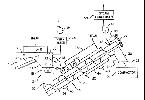
Figure 1 is a schematic diagram of a
preferred waste treatment apparatus in accordance with
the invention.
The complete treatment apparatus embodying the
invention comprises two principal components: a shredding
apparatus 2 and a heat treatment apparatus 4, through
which shredded waste is conveyed slowly while being
subjected to direct steam impingement and dehydration.
In the embodiment if treatment apparatus illustrated
in the drawing, the shredding apparatus 2 includes an
inclined belt conveyor 6 inside a housing B. The
conveyor receives waste material, typically bags, boxes
or "sharps" containers of regulated medical waste,
through an intake opening 10. A bag of waste 12 is shown
on the conveyor. Alternatively, other forms of conveyor
5
CA 02250376 1998-10-15
can be used to carry the waste material into the
apparatus. For example, a cart elevator, a dumper, a
combination cart elevator and dumper, or other suitable
conveyor can be used instead of the belt conveyor.
A hopper section 14 underneath the upper end of the
conveyor conducts the packaged waste to a shredding
mechanism 16 comprising conventional, cooperating
rotating cutters. The shredding mechanism can be made in
a variety of configurations which can be selected
depending on the materials being handled. For example it
can include a two-shaft or four-shaft shredder, or plural
two-shaft shredders or any of many other shredder
configurations.
A reciprocating ram mechanism 18, on a hinge 20,
includes a pusher plate 22, which assists gravity in
moving waste into the shredding mechanism by applying
downward pressure to the waste containers in the hopper
section 14. Other forms of rams, for example, piston
rams, can be used
A blower 24 draws air from the housing 8 through a
high efficiency particulate air (HEPA) filter 26. This
maintains an inward flow of air through the intake
opening 10, thereby preventing particles from being
discharged through the intake opening. An interlock (not
shown) is preferably provided for preventing the
introduction of raw waste material unless the blower 24
is drawing air through the intake opening.
Sanitizing spray nozzles 27 introduce a sanitizing
solution (preferably sodium hypochlorite in water) into
the housing 8 intermittently, to prevent the growth of
colonies of microorganisms in the housing 8 and in the
shredding apparatus 2.
6
CA 02250376 1998-10-15
The heat treatment apparatus 4 comprises an
inclined, elongated enclosure 28 having an entrance
opening 30 at its lower end for receiving shredded waste
material from the shredding mechanism 16, and an exit
opening 32 at its upper end for discharging processed
waste material.
The elongated enclosure preferably has a cylindrical
inner wall, and a helical screw conveyor 34 extending
through it for moving the shredded waste material from
the entrance opening 30 to the exit opening 32. The
helical screw conveyor preferably fits into the enclosure
with a small clearance between its blade and the
cylindrical inner wall of the enclosure. It is rotated
by a motor 36 through a chain 37.
Steam, supplied through a conduit 38, is injected,
at a pressure below 15 psi, into the interior of
enclosure 28 through a plurality of injection ports 40
spaced from one another in the longitudinal direction at
locations between the entrance opening 30 and an
intermediate location 42 between the entrance and the
exit opening. The steam injection ports bring steam into
direct contact with the shredded waste material within a
direct steam impingement section of the enclosure
extending from a location adjacent to entrance opening 30
to the intermediate location 42.
The screw conveyor 34 agitates and tumbles the
shredded waste material to enhance contact between the
steam and the waste material. Mixing tabs (not shown)
can be provided on the screw conveyor to enhance
permeation of the waste by the steam. The speed of the
screw conveyor is controlled so that the residence time
of the waste material in the steam impingement section is
approximately thirty minutes. Thermocouples 43 are
7
CA 02250376 1998-10-15
provided on the bottom of the enclosure 28. A first such
thermocouple operates a valve (not shown) which controls
the flow of steam to maintain the temperature of the
waste material along the length of the steam impingement
stage in the range of 205 F to 212 F, and preferably
between 205 F and 210 F.
Beyond the intermediate location 42, a steam jacket
44 surrounds the enclosure 28. The steam jacket
preferably receives steam at low pressure from the same
source that supplies steam to the direct impingement
stage. The steam in the steam jacket is maintained at a
temperature such that the surface of the inner wall of
the enclosure 28 is held at a temperature above 212 F,
and preferably at a temperature in the range of 220 F to
235 F. The steam is preferably delivered at a
temperature of 235 F, and condenses on the waste at a
temperature in the range of 205 F to 212 F. The steam
temperature in the jacket is controlled by a second
thermocouple 43, which is located on or within the steam
jacket and operates a valve (not shown) to control the
flow of steam.
The action of the screw conveyor ensures good
contact between the waste and the hot cylindrical inner
wall of enclosure 28. Thus, the steam jacket provides a
second stage of treatment in which the waste is brought
into contact with a hot surface so that moisture in the
waste material is converted to vapor. This stage serves
to dehydrate the waste material, reducing its weight.
To prevent the moisture in the vapor generated by
the heat of the steam jacket from returning to the waste,
moisture is exhausted from the interior of the enclosure,
at a location between the steam jacket and the exit, by a
blower 46, which is connected to a port 48. The steam is
8
CA 02250376 1998-10-15
either vented to the atmosphere, or a condenser 50 at the
outlet of the blower 46 may be used to return water to
the steam supply. The condenser is particularly useful
if the apparatus is located within a building. The
exhaustion of moisture takes place by virtue of the low
pressure maintained by blower 46 in the enclosure near
its exit opening 32. A flapper 52, with a counterweight
54, normally maintains the exit opening in a closed
condition so that low pressure chamber can be maintained
at the upper end of the conveyor. However, as waste
material accumulates within the exit opening, the flapper
opens under the weight of the waste material, permitting
the waste material to be discharged to a compactor 56.
The dehydration of the waste material is initiated
by the heat imparted to it by the steam jacket, and
completed by the exhaustion of water vapor from the low
pressure chamber. Thus, in the preferred embodiment of
the invention, the section surrounded by the steam jacket
and the low pressure chamber, together constitute a
dehydration stage.
The waste treatment apparatus does not depend on
chemical application for sterilization. The sanitizing
spray merely prevents the build-up of colonies of
microorganisms in the feed and shredding mechanisms, and
introduces minimal amounts of moisture into the waste.
The minimization of moisture introduction in the
preliminary stages improves the transfer of heat in the
direct steam impingement. It also improves the
efficiency of the dehydration stage in destroying
pathogenic microorganisms, and delivering a light-weight
waste product. The direct impingement of steam onto the
waste material helps to ensure complete destruction of
live microorganisms. Moisture introduced into the waste
9
CA 02250376 1998-10-15
material in the direct steam impingement stage is removed
in the dehydration stage of the apparatus.
Various modifications can be made to the apparatus
described. For example the screw conveyor can comprise
two or more sections separately controlled. Various
other modifications can be made to the apparatus, and to
the process for which it is used, without departing from
the scope of the invention as defined in the following
claims.