Language selection

Search

Patent 2250404 Summary

Third-party information liability

Some of the information on this Web page has been provided by external sources. The Government of Canada is not responsible for the accuracy, reliability or currency of the information supplied by external sources. Users wishing to rely upon this information should consult directly with the source of the information. Content provided by external sources is not subject to official languages, privacy and accessibility requirements.

Claims and Abstract availability

Any discrepancies in the text and image of the Claims and Abstract are due to differing posting times. Text of the Claims and Abstract are posted:

  • At the time the application is open to public inspection;
  • At the time of issue of the patent (grant).
(12) Patent: (11) CA 2250404
(54) English Title: VACUUM HOISTING DEVICE HAVING A VERTICALLY SUSPENDED LIFTING TUBE
(54) French Title: DISPOSITIF DE LEVAGE PNEUMATIQUE COMPRENANT UN TUYAU DE LEVAGE SUSPENDU VERTICALEMENT
Status: Deemed expired
Bibliographic Data
(51) International Patent Classification (IPC):
  • B66C 1/02 (2006.01)
  • B66F 3/35 (2006.01)
  • F15B 15/10 (2006.01)
(72) Inventors :
  • WICEN, JAN (Sweden)
(73) Owners :
  • PRONOMIC AB (Sweden)
(71) Applicants :
  • AB INITIO AFFARS- & TEKNIKUTVECKLING (Sweden)
(74) Agent: NORTON ROSE FULBRIGHT CANADA LLP/S.E.N.C.R.L., S.R.L.
(74) Associate agent:
(45) Issued: 2007-06-12
(86) PCT Filing Date: 1997-03-26
(87) Open to Public Inspection: 1997-10-09
Examination requested: 2002-03-25
Availability of licence: N/A
(25) Language of filing: English

Patent Cooperation Treaty (PCT): Yes
(86) PCT Filing Number: PCT/SE1997/000545
(87) International Publication Number: WO1997/036818
(85) National Entry: 1998-09-28

(30) Application Priority Data:
Application No. Country/Territory Date
9601232-3 Sweden 1996-03-29

Abstracts

English Abstract


The invention relates to a vacuum hoisting device
of the kind having a vertically suspended lifting tube (4),
which is extensible and contractible in dependence on the
air pressure in the lifting tube, and which at its lower part
is provided with a suction device (6) in the shape of one or
more suction cups. Up to now a valve at the suction device
is used for manoeuvering the suction device, which valve
when closed brings a vacuum source (7, 20) to work with
a constant suction capacity to decrease the pressure in the
lifting tube such that an object (32) to be lifted is attached
by the suction after which the lifting tube is contracted
such that the object is lifted. To limit the lifting height
and to lower and release the object it has been necessary to
partially open the valve and permit a restricted inlet of air
and at last completely open the valve resulting in a large
comsumption of air. According to the invention there is
instead a valve (14, 23) arranged to control the suction
capacity of the vacuum source in direct dependence of
the desired air pressure in the lifting tube (4).


French Abstract

Dispositif de levage pneumatique du type comprenant un tuyau (4) de levage suspendu verticalement qui peut s'étirer et se contracter en fonction de la pression de l'air à l'intérieure du tuyau de levage et qui est équipé au niveau de sa partie inférieure d'un dispositif d'aspiration (6) se présentant sous forme d'une ou plusieurs ventouses. Jusqu'à présent, le système utilisé comprenait une soupape située au niveau du dispositif d'aspiration ou manoeuvrer ce dernier, ladite soupape, lorsqu'elle est fermée, mettant en oeuvre une source (7, 20) de vide avec une capacité d'aspiration constante pour faire baisser la pression dans le tuyau de levage de sorte qu'un objet (32) à lever est maintenu par l'aspiration, le tuyau de levage se contractant ensuite de manière à soulever l'objet. Pour limiter la hauteur de levage et pour faire descendre et relâcher l'objet, il a été nécessaire d'ouvrir partiellement la soupape et de laisser entrer une quantité d'air restreinte pour finir ensuite par ouvrir complètement la soupape ceci ayant pour effet de consommer une grande quantité d'air. Dans cette invention on a remplacé le système précédent par une soupape (14, 23) disposée de manière à réguler la capacité d'aspiration de la source de vide directement en fonction de la pression d'air désirée dans le tuyau (4) de levage.

Claims

Note: Claims are shown in the official language in which they were submitted.


-4-
CLAIMS

1. A vacuum hoisting device for lifting in a lift cycle an
object having a weight, the vacuum hoisting device comprising:
(a) a vertical lifting tube suspended at an upper part,
the vertical lifting tube being axially extensible and
contractible depending upon air pressure in the vertical
lifting tube;
(b) a vacuum source having a suction channel connected to
the interior of the vertical lifting tube and having a suction
capacity;
(c) at least one suction cup at a lower part of the
vertical lifting tube; and
(d) a regulating device located in an energy input to the
vacuum source and operated by an energy input regulator
located near the suction cup to manually adjust energy input
to the vacuum source during the lift cycle to control the
suction capacity of the vacuum source depending on a desired
air pressure in the vertical lifting tube, the desired air
pressure being a function of the weight of the object being
lifted.

2. A device according to claim 1, wherein the vacuum source
includes an ejector device driven by compressed air, the
regulating device and energy input regulator being arranged to
control the suction capacity through flow of compressed air to
the ejector device.

3. A device according to claim 2, wherein the ejector device
and the regulating device are mounted at the upper part of the
vertical lifting tube, and further including a device
extending down from the regulating device for remote control
of the regulating device to which the energy input regulator
is attached.


-5-
4. A device according to claim 3, wherein the device
extending down from the regulating device is a bowden control
cable.

5. A device according to claim 2, wherein the ejector drive
is attached to the upper part of the vertical lifting tube,
and a compressed air tube is attached to the ejector device
and extends down in a loop where the regulating device and the
energy input regulator for controlling flow of compressed air
are mounted.

6. A device according to claim 1, wherein the vacuum source
is driven by an electric motor, the regulating device and the
energy input regulator are arranged to control motor speed and
thereby control the suction capacity of the vacuum source.

7. A vacuum hoisting device comprising:

(a) a vertical lifting tube suspended at an upper part,
the vertical lifting tube being axially extensible and
contractible depending upon air pressure in the vertical
lifting tube;

(b) a vacuum source connected to the vertical lifting
tube and having a suction capacity, the vacuum source includes
an ejector device driven by compressed air, the ejector device
attached to the upper part of the vertical lifting tube;

(c) at least one suction cup at a lower part of the
vertical lifting tube;

(d) a regulating device upstream of the vacuum source and
operated by an energy input regulator to manually adjust
energy input to the vacuum source to control the suction


-6-
capacity of the vacuum source and thus the air pressure in the
vertical lifting tube, the regulating device and energy input
regulator being arranged to control the suction capacity
through flow of compressed air to the ejector device; and

(e) a compressed air tube attached to the ejector device
and extending down in a loop where the regulating device and
the energy input regulator for controlling flow of compressed
air are mounted.

Description

Note: Descriptions are shown in the official language in which they were submitted.


CA 02250404 1998-09-28

WO 97/36818 PCT/SE97/00545
Vacuum hoisting device having a vertically suspended lifting tube.

The present invention relates to a vertical lifting tube suspended at its
upper part and of the type set forth in the introduction of the accompanying
claim 1.
Hoisting devices of this type are known for instance by SE 451 834,
and are provided with a valve device at the lower part of the lifting tube
by means of which surrounding air, when required, can be let into the interior
of the lifting tube such that the air pressure in the lifting tube can
be regulated to permit lifting and lowering of the lower part of the lifting
tube in a desired manner. This results in an extremely simple mode of
operating of the lifting device by holding an object by suction, lifting
the suction device and the object, lowering same, and delivering of the
object only by the aid of the valve device.
A drawback to this known type of hoisting device consists of the
fact, that the vacuum device, a vacuum pump or an ejector device driven
by ccmpressed air, is operated all the time with maximum vacuum flow that
is dimensioned for the heaviest case of load and for fast lifting operations.
As soon as the lifting operation is finished after 1-2 seconds the demand
of vacuum flow is essentially reduced in dependence on how much leakage
there is through the object that is lifted an~3 around the edges of the
suction device. This means that it is necessary to let in air into the
lifting tube corresponding to the over-capacity of the vacuum source. If
this is not made the vacuum level in the lifting tube will increase and
the load rise to maximum lifting height which is not desirable. All the
air let in generates a completely unnecessary pumping work which calls
for unnecessarily strong dimensioning of the pump and raises the manufacturing
costs as well as .he operating costs. Vacuum flows of this magnitude normally
also make it necessary to use fans and make it impossible to use simple
and easily applicable ejectors driven by compressed air.
The object of the invention is to achieve a simple and economically
working lifting device of the kind mentioned in the introduction where
the above mentioned drawbacks are eliminated.
This is achieved according to the invention in that the vacuuia lifting
device has obtained the characterizing features set forth in the claim.
Instead of regulating the vacuum level in the lifting tube in the known
way by letting in air through a valve the invention prescribes a solution
of the pro-blem of controlling the lifting tube by using the valve for


CA 02250404 1998-09-28

WO 97/36818 2 PCT/SE97/00545
controlling the suction capacity of the suction source or in other words
the vacuum flow. Hence, the vacuum flow is heavy during the very lifting
operation but after that not heavier than the leakage into the lifting
tube. This can suitably be obtained in the various ways set forth in the
claims 2-5.
The invention will now be disclosed more in detail with reference
to the accomp3nying drawings showing by way of example various embodiments
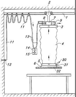
of devices according to the invention in which Figure 1 is a longitudinal
section through a first embodiment of the invention, Figure 2 is a side
view of a second embodiment, and Figure 3 is a side view of a further
embodiment.
Fig.l shows a rail 1 on which a trolley 2 is travelling. The upper
part 3 of a lifting tube 4 is hanging from the trolley. The lower part
is provided with one or more suction cups 6, and a vacuum source comprising
an ejector 7 driven by compressed air and provided with a silencer 8 and
an air filter 9 is mounted on the upper part 3. The suction side of the
ejector 7 is via a channel 10 connected to the interior of the lifting
tube 4. The ejector 7 is driven from a compressed air tube 11, which via
a loop 13 hanging down from the ejector and the compressed air tube is
connected to the ejector and at the other end to a nipple 12 belonging
to a central compressed air plant. A valve 14 for regulating the flow of
compressed air is connected to the lowest part of the loop and controlled
by a manually operated regulating means 15. The control of the lifting
tube, thus, is obtained by regulating the pressure of the driving air to
th-a ejector instead of driving the ejector or other vacuum source all the
time at maximum capacity, as previously made. In some cases when it is
necessary to obtain short lifting time periods it may be suitable to have
two ejectors connectable, one big ejector for the lifting phase and on~-:~
smaller ejector automatically connectable for maintaining the vacuum level
as lozg as the load is kept at a constant lifting level.
In this way the air and energy consimption is essentially reduced
after the load has been lifted from a support. An air supply cycle consisting
of lifting, transport azd lowering may extend ove- about 40 seconds with
a lifting time period of 4 seconds. It can easily be shown that with a
:ievice according to the invention a reduction of the air consumption during
an air supply cycle amounting ;:o 43% is obtained in co:tparison with
previously
known devices.
The device shown in Fig.2 differs from the device Showa in Fig.l


CA 02250404 1998-09-28

WO 97/36818 3 PCT/SE97/00545
by the valve 14 being connected in the compressed air tube 11 at its
connection to the ejector 7 and arranged to be controlled by a regulating
means 16, which is connected to the valve 14 by a bowden control cable
17 or similar hanging down fran the ejector.
As an alternative the vacuum source may consist of a vacuum pump
20 driven by an electrical motor 21, as shown in Fig.3. The upper part
3 with the channel 10 of the lifting tube 4 is connected to the suction
side of the vacuum pump 20 via a suction tube 22. The current consumption
of the motor 21 is regulated by a current valve 23 belonging to the supply
circuit (not shown) of the motor, which valve is remote controlled in a
suitable way, for instance by a bowden control cable 24 with a regulating
means 25 connected to the bowden cable.
The invention is of course not limited to the embodiments shown and
described here but can be modified in various ways within the scope of
the inventive idea defined by the claims. At the embodiment according to
Fig.3 the suction tube 22 may, as an alternative, be connected to a central
suction circuit with a valve 14 connected in the suction tube for controlling
the suction flow in a way similar to the way described above. Further,
at all embodiments the lower part of the lifting tube may be provided with
a handle 30 for manoeuvring of the suction device consisting of the suction
cup or cups and a manually operated valve 31 in connection to the handle
for letting in air into the lifting tube in order to achieve a rapid lowering
of the suction device and release of the object handled by the suction
device, especially when the object is an air impervious object 32. Also
a vacuum pump driven by an electric motor may, of course, be mounted on
top of the upper part 3 of the lifting tube in a similar way as the ejector
device in Figs.l and 2. Further, the motor-driven vacuum pump in Fig.3
may be replaced by an ejector device. The components at the upper part
3 of the lifting tube as well as the connection of the suction tube 22
may also be moved to the lower part 5 the lifting tube.

Representative Drawing
A single figure which represents the drawing illustrating the invention.
Administrative Status

For a clearer understanding of the status of the application/patent presented on this page, the site Disclaimer , as well as the definitions for Patent , Administrative Status , Maintenance Fee  and Payment History  should be consulted.

Administrative Status

Title Date
Forecasted Issue Date 2007-06-12
(86) PCT Filing Date 1997-03-26
(87) PCT Publication Date 1997-10-09
(85) National Entry 1998-09-28
Examination Requested 2002-03-25
(45) Issued 2007-06-12
Deemed Expired 2010-03-26

Abandonment History

There is no abandonment history.

Payment History

Fee Type Anniversary Year Due Date Amount Paid Paid Date
Application Fee $150.00 1998-09-28
Maintenance Fee - Application - New Act 2 1999-03-26 $50.00 1998-09-28
Registration of a document - section 124 $100.00 1999-09-28
Maintenance Fee - Application - New Act 3 2000-03-27 $50.00 2000-03-08
Maintenance Fee - Application - New Act 4 2001-03-26 $50.00 2001-03-15
Maintenance Fee - Application - New Act 5 2002-03-26 $150.00 2002-03-05
Request for Examination $200.00 2002-03-25
Maintenance Fee - Application - New Act 6 2003-03-26 $150.00 2003-03-03
Maintenance Fee - Application - New Act 7 2004-03-26 $200.00 2004-03-03
Registration of a document - section 124 $100.00 2004-04-22
Maintenance Fee - Application - New Act 8 2005-03-28 $200.00 2005-03-03
Maintenance Fee - Application - New Act 9 2006-03-27 $200.00 2006-03-07
Expired 2019 - Corrective payment/Section 78.6 $500.00 2006-06-14
Final Fee $300.00 2007-01-24
Maintenance Fee - Application - New Act 10 2007-03-26 $250.00 2007-03-12
Maintenance Fee - Patent - New Act 11 2008-03-26 $250.00 2008-03-05
Owners on Record

Note: Records showing the ownership history in alphabetical order.

Current Owners on Record
PRONOMIC AB
Past Owners on Record
AB INITIO AFFARS- & TEKNIKUTVECKLING
WICEN, JAN
Past Owners that do not appear in the "Owners on Record" listing will appear in other documentation within the application.
Documents

To view selected files, please enter reCAPTCHA code :


To view images, click a link in the Document Description column. To download the documents, select one or more checkboxes in the first column and then click the "Download Selected in PDF format (Zip Archive)" or the "Download Selected as Single PDF" button.

List of published and non-published patent-specific documents on the CPD .

If you have any difficulty accessing content, you can call the Client Service Centre at 1-866-997-1936 or send them an e-mail at CIPO Client Service Centre.


Document
Description 
Date
(yyyy-mm-dd) 
Number of pages   Size of Image (KB) 
Description 1998-09-28 3 177
Claims 1998-09-28 1 49
Drawings 1998-09-28 3 51
Cover Page 1998-12-14 2 73
Abstract 1998-09-28 1 56
Representative Drawing 1998-12-14 1 7
Claims 2006-04-10 3 75
Claims 2005-03-07 3 73
Representative Drawing 2006-12-06 1 9
Representative Drawing 2007-05-23 1 10
Cover Page 2007-05-23 1 47
Prosecution-Amendment 2004-09-08 2 43
Correspondence 1998-12-01 1 32
PCT 1998-09-28 8 291
Assignment 1998-09-28 4 139
Assignment 1999-09-28 3 135
Prosecution-Amendment 2002-03-25 2 37
Prosecution-Amendment 2002-03-25 2 52
Correspondence 2002-03-25 3 85
Assignment 2004-04-22 2 75
Prosecution-Amendment 2005-03-07 5 119
Prosecution-Amendment 2005-10-11 2 40
Prosecution-Amendment 2006-04-10 3 76
Prosecution-Amendment 2006-06-14 2 53
Correspondence 2006-06-23 1 16
Correspondence 2007-01-24 1 39