Note: Descriptions are shown in the official language in which they were submitted.
CA 022~i0~ i 1998-10- l~i
ere~:(J:3:lG2~IDs Ll33G~!zHou 2 ~3()GIIFI
- 1
CELLULAR WIRELESS COMMUNICATION SYSTEM
WITH FIXED T~MTN~LS
This invention relates to cellular wireless
communication systems (e.g. GSM radio systems) with fixed
terminals.
Cellular radio communication systems are largely
used to provide telephone and/or data services to mobile
terminals. In competition with traditional telephone
services where the subscriber is connected by land line to
the switching centre, cellular radio systems service
providers have been seeking to provide service to fixed
terminals. A fixed terminal can use a highly directional
antenna allowing its communication channels to be reused at
a closer base station than would otherwise be the case.
That is the number of times that a frequency band can be re-
used is increased. That allows the telephone service
provider to reduce the charge rate for the fixed service so
that it is competitive with services provided via land line.
Against this background there is provided a cellular
wireless communication system, providing communication
between base stations and mobile or fixed terminals,
including a fixed installation comprising a fixed
directional antenna directed at a predetermined base station
and an interface for providing communications between a
mobile terminal and the antenna, wherein when communication
is via the interface, information transmitted on the up link
CA 022~0~l~ l998- l0- l~
case rer: G3362/IDS 113362/ZHOU ~ 98061lFI
signalling channel includes an indication that the fixed
antenna is in use, and wherein the base station has an array
of two or more antennas and means responsive to receipt of
said indication to adjust the phases of down link
transmissions from individual antennas to produce a lobe
directed at the known position of the fixed installation;
and to reduce the power of down link transmissions to the
fixed installation. This allows a subscriber to use one
mobile telephone set for both fixed and mobile
communications, so having only one account, and may allow
the telephone service provider to reduce the charging rate
for the fixed service to a level which is competitive with
service provided via landline.
In one form, the interface includes a connector and
the mobile terminal includes a switch or proximity detector
which is operated when the connector is connected to the
mobile station, the mobile terminal being responsive to
operation of the switch or proximity detector to transmit
said indication.
In another form, the interface includes a radio
transmitter/receiver for communication with the mobile
terminal.
The interface may include means storing a code
readable by the mobile which is responsive to the code to
transmit said indication.
In that form, the indication transmitted may be the
code.
CA 022~0~1~ 1998-10-1~
case re! (',3:31i~!1DS 118:3i;'~/ZHOU ~ 980~illFI
In an alternative form the interface includes a
processor operable to encrypt a data word received from the
mobile terminal and to return the encrypted word to the
terminal, the mobile terminal performs a similar encryption
and only if the two encrypted words are the same is the
indication transmitted to the base station.
The base station may have a plurality of antennas
each with a respective tapped delay line in which the tap
output signals are weighted and summed, and wherein on
receipt of the indication, the weights are determined so as
to direct a lobe at the known position of the fixed
installation. That allows a further reduction in power of
transmissions on the up link, further reducing interference
by the fixed station and allowing up link channels to be
reused by a closer base station or mobile terminal than
otherwise and/or reduces interference.
The system preferably includes a charging centre
which during a call in which the base station receives the
indication, reduces the charge rate.
Embodiments of the invention will now be described,
by way of example with reference to the accompanying
drawings, in which:
Figure 1 is a schematic representation of a fixed
installation in a cellular wireless communication system
embodying the invention; and
Figure 2 is a schematic representation of an antenna
array at a base station in a system embodying the invention;
CA 022~i0~ i 1998-10- l~i
C~l.'il' rcl: (~8:3ii2,'IDS Ll:3:3ti2/ZHOU :2 ')81)~;1LFL
Figure 3 is a schematic representation of another
system embodying the invention; and
Figure 4 is a block diagram showing features of the
base station.
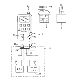
Referring to the drawing, a building e.g. a
subscriber's home 2, has a directional antenna e.g. a Yagi
antenna 4 fixedly mounted thereon. The antenna 4 is designed
to have a thin pencil beam in its polar both for reception
and transmission. The beam is directed at a base station 6.
The antenna 4 is connected via a coaxial cable to an
interface unit 10. The interface unit 10 includes a
multiway connector 12 for connection to a complementary
connector 14 in a mobile telephone set 16. A switch 18 is
operated when the connector 12 is connected to change switch
contacts 20 over so connecting the output of the telephone~s
wide band power amplifier 22 to the cable 8 through the
connector 12 instead of to the mobile's omnidirectional
antenna 24.
The switch 18 may have an operating member (not
shown) which is depressed by the connector 12 when connected
or may be in the form of a proximity switch operated by a
magnet 26 in the connector 12.
The connector 12 also connects the telephone set 16
to a power supply unit 28 in the interface 10.
Operation of the switch or proximity detector 18 may
also be used to trigger the transmission on the signalling
channel in use by the mobile of an indication that it is
CA 022~0~1~ 1998-10-1~
~serefG33~2/IDS113362/ZHOU2 980611FI
- 5
connected to its fixed antenna installation.
Because the antenna is directional, communications
on the uplink will be much less likely to interfere with
other stations than communications via the mobile
telephone~s omnidirectional antenna 24. Knowing that, the
system can reuse channels in use by the mobile via its fixed
installation at base station or mobile which is at a much
reduced distance compared with the position with the
omnidirectional antenna 24. The directional qualities of
the antenna 4 also lead the base station 6 to instruct the
mobile terminal to transmit at reduced power, compared with
the power which would be needed with the omnidirectional
antenna 24, which further reduces interference.
Referring to Figure 4, the base station 6 has a
plurality of antennae 30 in a diversity array, each
connected to respective duplexers 50. Transmitter and
receiver circuits 52 and 54 are connected to each of the
duplexers so that signals can be both transmitted and
received through the same antennae. The receiver circuit
includes the space time processors shown in Figure 2. As
the position of the fixed installation is known, a
controller 56 iS responsive to receipt of the indication, to
adjust the output phases of the transmitter circuit 52 SO
that the antennae 30 produce a narrow beam directed at the
antenna 4 and reduces the power.
The controller also provides information allowing
the channel in use between the fixed installation and the
CA 022~0~1~ 1998-10-1~
c3se rei: G33fi2/rDS 1133~;2/ZHOU 2 980~11FI
mobile station, to be re-used in an adjacent cell, and
instructs a charging centre to reduce the rate for the
call.
Since the antenna 4 also produces a stronger signal
received from the base station 6, the base station can
further reduce the power on its downlink communications with
the mobile terminal 16.
On the uplink, each antenna 30 in the array has a
respective space/time processor 32, shown in Figure 2,
comprising a delay line 34 having taps at spacings of Ts
equivalent to one symbol interval. The outputs from each
tap are weighted by a vector w and the weighted outputs are
summed in a summer 36. The sums are summed in a summer 38.
As the position of the fixed installation is known a
predetermined set of weights can be loaded into the
space/time processors so as to steer the array at the
antenna 4.
The simple system described above in which a switch
or proximity detector 18 is operated by the connector 12,
may be open to abuse and is only possible when the interface
includes a connector 12. In order to better ensure that the
cheap rate is only given to mobiles when attached to the
antenna 4, the interface 10 may include means 40 for storing
a code. In a simple example the means 40 may comprise a set
of switches, e.g. a DIP (dual in line switch). The switches
may be set to a predetermined code readable via a bus 42 by
the mobile terminal 16. The code may be utilised in various
,
CA 022~0~1~ 1998- lO- l~
c~se rcl: G.'3:3ti2/~DS 11:3:3ti2!ZHOI.' ~ 980611FI
- 7
ways. For example the mobile terminal may only transmit the
attached to antenna indication if the code is the same as
one stored in the mobile. Alternatively, the code may be
transmitted and a comparison may be made at the base
station.
In another alternative, the interface 10 may also
include a processor 42 operable under control of a program
stored in store 40 to encrypt a data word received from the
mobile and to return the encrypted word over the bus 42.
The mobile performs a similar encryption and only if the two
encrypted words are the same is the antenna attached
indication transmitted to the base station.
In order to allow the user some mobility, the
interface 10 shown in Figure 3 communicates with the mobile
terminal 16 via radio channels provided by a low power
transmitter and receiver 44 and ceiling mounted antenna 46.
The channels may be the same or different from the channel
used for communication via the fixed antenna with the base
station. In this case the interface may, itself, add the
indication that the fixed antenna is in use to the up link
signalling information. In the embodiment of Figure 3 an
array of antennas 4 is provided. A beam forming unit 48
adjusts the signals to each antenna to form a thing pencil
beam directed at the base station 6, both for reception and
transmission.