Note: Descriptions are shown in the official language in which they were submitted.
CA 022~0~34 1998-10-30
,
PATENT
ULTRASONIC COMB PROBE ARRAY ASSEMBLY
FIELD OF THE lNv~NllON
This invention relates to the ultrasonic testing
of materials, and in particular to an ultrasonic comb
probe array assembly for generating ultrasonic waves in
an object.
BACKGROUND OF THE lNV ~:N-LloN
Ultrasound is commonly used to locate
discontinuities and other imperfections in materials and
to characterize materials and measure distances.
Conventional ultrasonic testing employs longitudinal or
shear waves in a point by point inspection of the object.
More recently, ultrasonic guided wave techniques have
been developed. See, generally Rose, Rajana, and Carr,
Ultrasonic Guided Wave Inspection Concepts for Steam
Generator Tubing, Materials Evaluation, February 1993,
Page 307, incorporated herein by reference. These
ultrasonic guided wave techniques involve launching
CA 022~0~34 1998-10-30
ultrasonic waves at one position on an object, which
propagate for substantial distances within the object,
"guided" by the boundaries of the object. Defects in the
object reflect the guided waves, and thus can be
identified and located by monitoring the received waves.
Ultrasonic guided wave techniques offer several
advantages over other ultrasonic inspection techniques,
including the ability to simultaneously inspect the
entire cross-section and length of an object; the
elimination of complicated and expensive apparatus for
positioning and indexing conventional ultrasonic probes;
and increased sensitivity to some types of defects.
The design parameters for ultrasonic comb probes
include factors such as size, shape, frequency, frequency
band width, and coupling means. The probes currently in
use are designed and built for particular applications.
They are typically two pieces secured over the object,
each piece having a plurality of ultrasonic transducers
secured therein. One difficultly encountered with the
comb probes presently available is that they are fragile
and prone to failure. High energies used in some
applications and the inefficiencies in the piezoelectric
materials used in the transducers may cause some of this
energy to be dissipated as heat. This heat can causes
thermal stresses in the probe which can lead to failure
of the ultrasonic transducer elements. Failure of a
single element in conventional probes requires
replacement of the entire probe.
Another difficulty encountered with the presently
available comb probes is that the spacing between the
transducers is fixed and can not be changed. Thus probe
arrays are constructed for particular modes of operation.
In guided wave applications, available construction
techniques require that a different probe array be used
for each different guided wave mode.
CA 022~0~34 1998-10-30
.
Still another difficulty encountered with
presently available comb probes is coupling to objects
whose surfaces are not perfectly smooth. Because of the
rigidity of presently available arrays, if one element
contacts a high point on the surface of the object, there
will be a gap between the other elements and the surface.
While in some cases these gaps can be bridged with a
couplant, direct contact between the transducer and the
object is preferable.
SUMMARY OF THE lNv~NLlON
The present invention provides an ultrasonic probe
array assembly that is of simple, yet robust
construction; that resists overheating of the
transducers; that allows for replacement of failed
transducers; that allows the spacing between the
transducers to be changed; and which allows better
coupling between the individual transducers and the
surface of the object. Generally the array assembly of
the present invention comprises a plurality of probe
heads, each probe head comprising first and second
supports. There is a transducer mounted on each support.
The supports are hingedly connected to allow relative
pivoting movement of the first and second supports in a
plane. The probe heads are connected together in a
parallel, spaced relation, with their hinged connections
generally aligned. The probe heads are preferably
separated by replaceable spacers, so that spacing between
the probe heads can be changed.
This construction allows the individual probe
heads to be replaced, and allows the spacing of the heads
to be changed to generate different guided wave modes.
The use of separate probe heads and spacers also reduces
heat build up, reducing the risk of heat damage to the
transducers and damage to the array assembly from thermal
stresses.
CA 022~0~34 1998-10-30
The array assembly of the present invention is
mounted on the test object with the individual probe
heads of the array assembly each surrounding a portion of
the object. These individual probe heads better
accommodate variations in the surface of the test object,
achieving better contact between the transducers and the
object.
The array assembly of the present invention thus
provides a simple yet robust apparatus for the ultrasonic
guided wave testing of objects. The apparatus is
resistant to heat damage and thermal stresses, it allows
failed transducers to be easily replaced, it permits
adjustment of the spacing between the transducers, and it
achieves better contact between the transducers and the
surface of the test object. These and other features and
advantages will be in part apparent, and in part pointed
out hereinafter.
BRIEF DESCRIPTION OF THE DRAWINGS
Fig. 1 is a perspective view from above of a comb
probe array assembly constructed according to the
principles of this invention;
Fig. 2 is a perspective view from below of the
comb probe array assembly;
Fig. 3 is a perspective view from the front of the
comb probe array assembly;
Fig. 4 is a an exploded perspective view of the
comb probe array assembly; and
Fig. 5 is an exploded perspective view of one of
the probe heads comprising the comb probe array assembly.
Corresponding reference numerals indicate
corresponding parts throughout the several views of the
drawings.
CA 022~0~34 1998-10-30
DETAILED DESCRIPTION OF THE PREFERRED EMBODIMENT
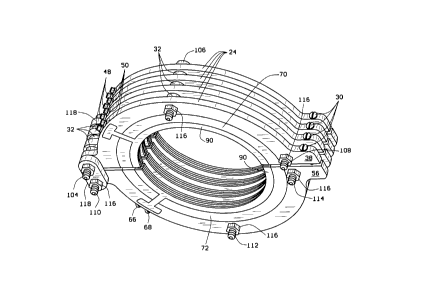
A comb probe array assembly constructed according
to the principles of this invention is indicated
generally as 20 in the Figs 1-4. The assembly 20
comprises a plurality of probe heads 22. Each probe head
22 comprises first and second supports 24 and 26. The
first and second supports 24 and 26 are hingedly
connected at one end for relative pivotal movement in a
plane. Each of the first and second supports includes a
transducer 28. Fasteners 30 between the first and second
supports, can secure the supports around an object and
hold their respective transducers 28 in intimate contact
with the surface of an object.
As shown in Figs. 1-4, the probe heads 22 are
arranged in a stack in parallel, spaced relationship,
with the hinged connections generally aligned. There are
preferably spacers 32 between adjacent probe heads 22.
These spacers are preferably replaceable, as described
below, so that the spacing of the probe heads 22, and
more particularly the spacing of the transducers 28 on
the probe heads, can be changed.
As best shown in Fig. 5, the supports 24 and 26
are mirror images of one another. The first support 24
comprises a generally semicircular housing 34 having tabs
36 and 38 projecting from the front and rear ends of the
body, and a semicircular recess 40 in one face, adjacent
the inner circumference of the semicircular housing. The
housing 34 is preferably made of aluminum, which is rigid
and light weight, yet easy to machine. There is a
generally T-shaped cutout 42 formed in the same face of
the housing 34. The bottom of the stem of the "T"
communicates with the semicircular recess 40. Two radial
passages (not shown) extend from the outer circumference
of the semicircular housing 34 to the top of the ~T".
Connectors 48 and 50 are mounted in these passages for
CA 022~0~34 1998-10-30
making electrical connections with the probe head as
described below.
Similarly, the second support 26 comprises a
generally semicircular housing 52 having tabs 54 and 56
projecting from the front and rear ends of the housing,
and a semicircular recess 58 in one face, adjacent the
inner circumference of the semicircular housing. The
housing 52, like housing 34, is preferably made of
aluminum. There is a generally T-shaped cutout 60 formed
in the same face of the housing 52. The bottom of the
stem of the "T" communicates with the semicircular recess
58. Two radial passages 62 and 64 extend from the outer
circumference of the semicircular body to the top of the
"T". Connectors 66 and 68 are mounted in these passages
for making electrical connections with the probe head as
described below.
Semicircular bodies 70 and 72 of an acoustic
damping material are seated in the recess 40 and 58 in
the first and second housings 34 and 52. The acoustic
damping material is preferably an epoxy or epoxy
composite, such as epoxy resin 2057 and catalyst 9
available from Grace Specialty Polymer, 55 Hayden Avenue,
Lexington, MA 02173. The body 70 has a semicircular
groove 74 on one face, adjacent its inner edge, and a
radially extending groove 76 extending from its outer
edge to the semicircular groove, that aligns with the T-
shaped cutout 42. Similarly, the body 72 has a
semicircular groove 78 on one face, adjacent its inner
edge, and a radially extending groove 80 extending from
its outer edge to the semicircular groove, that aligns
with the T-shaped cutout 60.
The transducers 28 are preferably semicircular
strips 82 and 84 of a piezoelectric material electrically
connected to semicircular conductors 86 and 88,
respectively. The piezoelectric material is preferably a
PZT (lead zirconate titanate) such as those disclosed in
CA 022~0~34 l998-l0-30
The Application of 1-3 Piezocomposites in Acoustic
Transducers, Wallace Arden Smith, Materials Division,
Code 1131, Office of Naval Research, Arlington, Virginia
22217-5000, incorporated herein by reference. This
composite may be cut into a strip and formed into a
semicircular configuration by scoring and bending, or the
composite may be sufficiently bendable. The conductors
86 and 88 are preferably semicircular pieces of
conventional fiberglass circuit board material with
copper clad conductor strips. Wires (not shown) soldered
to the copper cladding and to the piezoelectric material
electrically connect the conductors 86 and 88 to their
respective piezoelectric strips 82 and 84.
The piezoelectric strips 82 and 84 and their
associated conductors 86 and 88 fit within the grooves 74
and 78 in the bodies 70 and 72, respectively. The
transducers 28 are secured in their respective supports
with a polymer encapsulant 90 formed in situ. The
encapsulant may be an epoxy resin 2057 and catalyst 9
available from Grace Specialty Polymers, 55 Hayden Ave.,
Lexington, MA 02173. After setting the encapsulant can
be machined to have smooth surfaces even with the surface
of the housing.
As shown in Figs. 4 and 5, the first supports 24
each have three holes 92, 94, and 96 therein. The hole
92 iS located in the tab 36, the hole 94 iS located
generally in the center of the arc of the housing 34, and
the hole 96 iS located generally in the tab 38.
Similarly the second supports 26 each have three holes
98, 100, and 102 therein. The hole 98 is located in the
tab 54, the hole 100 is located generally in the center
of the arc of the housing 52, and the hole 90 is located
generally in the tab 56.
As best shown in Fig. 4, the probe heads 22 are
arranged in parallel, spaced apart relation. Bolt 104
extends through the aligned holes 92, bolt 106 extends
CA 022~0~34 l998-l0-30
through the aligned holes 94, and bolt 108 extends
through the aligned holes 96 in the first support 24.
Bolt 110 extends through the aligned holes 98, bolt 112
extends through the aligned holes 100, and bolt 114
extends through the aligned holes 102, in the second
support 26. Nuts 116 on the ends of the bolts 104, 106,
and 108 hold the supports 24 and spacers 32 together.
Similarly, nuts 116 on the ends of the bolts 110, 112,
and 114 hold the supports 26 and spacers 32 together.
The spacers are preferably made of nylon.
The bolts 104 and 110 extend through links 118
which hold the bolts together, thereby hingedly
connecting the first supports 24 on bolt 104 with the
second supports 26 on bolt 110.
A fastener 30 extends between the tabs 38 on the
first supports 24 and the tab 56 of the respective second
supports 26 to secure the supports around the object, and
hold the transducers 28 in contact with the surface of
the object.
OPERATION
In operation, a comb probe array assembly is
assembled from a plurality of probe heads 22 and spacers
32 selected to achieve the appropriate transducer spacing
for the intended guided wave mode. The connectors 48 and
50 on the first supports 24 and the connectors 66 and 68
on the second supports 26 are daisy chained together.
The array assembly 20 iS secured on the inspected part by
securing the individual probe heads 22 around the
inspected part with fasteners 30. There is enough
freedom in the assembly to allow the first and second
supports 24 and 26 of each probe head 22 to fit closely
against the surface of the pipe, holding their respective
transducers 28 in close proximity to the surface of the
pipe.