Note: Descriptions are shown in the official language in which they were submitted.
CA 02250613 1998-10-15
1
"ELECTRIC SUBMERGIBLE MOTOR PROTECTOR"
BACKGROUND OF THE INVENTION
1. Field of the Invention
The present invention relates to oil-filled protectors for use with
submergible
electric motors and, more particularly, for use with electric submergible
motors to be
suspended within wellbores.
2. Description of Related Art
Electric submergible pumping systems are widely used throughout the world for
recovering subterranean fluids from wellbores to the earth's surface. In many
wells,
there are deleterious fluids that can chemically attack the materials used in
the motor.
For example, hydrogen sulfide will chemically attack the copper used in the
motor's
windings. If these deleterious fluids are not prevented from entering the
motor, then the
motor will prematurely fail.
For the long term successful operation of such submergible pumping systems,
the electric motor must be supplied with uncontaminated cooling motor oil.
This
cooling oil is partially contained within one or more elastomeric bags within
a motor
protector. The elastomeric motor protector bags are generally cylindrical in
shape and
are sealed within an oil filled housing. The bags are filled with oil at the
time of
installation to an expanded state. With the rise of temperature caused by the
immersion
in the wellbore, as well as the thermal expansion caused by the operation of
the electric
motor, the bags tend to slightly expand even more. When the electric motor is
turned
off, the cooling oil cools and contracts. This contraction allows the motor
protector bag
to slightly deflate. The elastomer typically used for the elastomeric bags is
a saturated
nitrite.
CA 02250613 2005-04-04
2
A problem encountered is that several deleterious fluids can easily pass
through
the elastomeric bags and enter the cooling oil, and then attack the motor
windings and
other internal components. As used herein the term "deleterious fluids" means
any liquid
or gas that has a chemical reaction with or some other interaction with one or
more of
the internal workings of the motor that degrade the performance of the motor.
Examples of such deleterious fluids are hydrogen sulfide (H2S), carbon dioxide
(C02)
and methane (CH4). There is a need for a protector that has the needed elastic
properties and at the same time can prevent the passage of such deleterious
fluids.
S~~y OF THE INVE1VTION
The present invention has been contemplated to overcome the foregoing
deficiencies and meet the above described needs. Specifically, the present
invention is
an oil-filled protector for use with an electric submergible motor, and it
comprises a
housing connectable to an electric submergible motor, and an oil-filled
expandable
c~~' ~t~n the housing and in fluidic communication with the electric
submergible
motor. The expandable chamber is formed from an elastomeric material, and
includes
materials for preventing deleterious fluids, such as H2S, C02 and CH4, from
passing
through the chamber and into the. motor. Such materials include elastomeric
materials
with one or more metallic coatings or bonded layers. The chamber can also
include
separate annular partitions to define an inner oil-filled region and an outer
region filled
with a barrier fluid that substantially inhibits the passage of the
deleterious fluids.
Accordingly, in one aspect, the invention provides a motor protector for use
in an
electric submergible pumping system, the motor protector comprising a motor
protector
housing connectable to an electric submergible motor, and an expandable member
within
CA 02250613 2005-04-04
2a
the motor protector housing, the expandable member having a liquid-filled
interior
chamber in fluid communication with the electric submergible motor, wherein
the
expandable member comprises an elastomeric layer and a deleterious ~ fluid
barrier
disposed adjacent the elastomeric layer.
In another aspect, the invention provides an oil-filled protector for use with
an
electric submergible motor, the protector comprising a motor protector housing
connectable to an electric submergible motor, an oil-filled expandable chamber
within
the motor protector housing and in fluidic communication with the electric
submergible
motor, and the oil-filled expandable chamber being formed from an elastomeric
material
and including means for preventing deleterious fluids from passing through the
oil-filled
expandable chamber.
BRIEF DESCRIPTION OF THE DRAWINGS
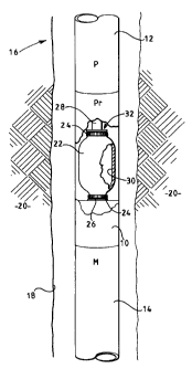
Figure 1 is a vertical partial cut-away view of an oil-filled electric motor
protector, shown operationally interconnected between a pump and an electric
motor,
and suspended within a subterranean wellbore.
CA 02250613 1998-10-15
3
Figures 2 - 5 are vertical sectional views of alternate preferred embodiments
of
an elastomeric bag for use within an oil-filled electric motor protector.
DETAILED DESCRIPTION OF THE PREFERRED EMBODIMENTS
For the purposes of the following discussion it will be assumed that the
elastomeric bag of the present invention is used within an oil-filled electric
motor
protector of the type used with submergible electric motors to be suspended
within
wellbores. However, it should be understood that the present invention can be
used
within any other type of downhole or surface motor, pump, turbine or other
industrial
machine that requires the use of an elastomeric body with improved resistance
to the
passage of deleterious fluids.
Electric motor protectors are well known to those skilled in the art, and they
provide the capability for thermal expansion of the electric motor's cooling
oil, they
provide isolation of the cooling oil from wellbore fluids, and they usually
contain thrust
bearings to absorb the axial loading of the pump that is connected thereto.
Figure 1
illustrates one preferred embodiment of a motor protector 10 of the present
invention
connected, in any well known manner, between a pump 12 and an electric motor
14.
The arrangement of the motor protector 10, the pump 12 and the electric motor
14 is
commonly referred to as an electric submergible pumping system or "ESP" 16.
Figure
1 shows the ESP 16 suspended within a wellbore 18 that penetrates one or more
earthen
formations 20.
An interior of the motor protector 10 contains one or more generally
cylindrical
elastomeric bladders, chambers or "bags" 22, which are clamped on each end by
annular
brackets or rings 24 against spaced inner brackets and/or shaft seals 26. A
shaft 28
passes through the interior of the bags 22 and connects the drive shaft (not
shown) of
CA 02250613 1998-10-15
4
the motor 14 to the rotor shaft (not shown) of the pump 12. An interior 30 of
each bag
22 is filled with dielectric cooling oil that is conveyed to and from the
electric motor 14
through internal passages (not shown) in the protector 10 and the motor 14, as
is well
known to those skilled in the art.
S The elastomeric bag 22 is preferably formed as a single continuous body,
without
a seam or weld, and has a thickened portion or bead 32 adjacent each mouth or
end
opening 34. The bag 22 is preferably formed primarily from an elastomeric
material that
provides desired elasticity at wellbore temperatures. Suitable elastomeric
materials
include nitrile rubber, tetrafluoroethylene-propylene copolymers, vinylidene
fluoride
hexafluoropropylene copolymers, virtually saturated acrylonitrile-butadiene
copolymers,
vinylidene fluoride-perfluoromethylvinylether-tetrafluoroethylene terpolymers,
vinylidene
fluoride hexafluoropropylene tetrafluoroethylene terpolymers, ethylene
propylene diene
methylene-based polymers, and combinations thereof. One or more bonded layers
of
such materials) can be used as is desired.
As has been described above, deleterious fluids, such as H2S, C02 and CH4, can
readily pass through the elastomeric material under wellbore conditions, enter
the
cooling oil, and then chemically attack the internal components of the motor
14.
Numerous attempts have been made to prevent such deleterious fluids from
entering the
motor 14 through the protector 10. Some of these attempts include having the
shaft
seals 26 and/or the bags 22 made from materials with better resistance to
penetration by
the deleterious fluids, and including scavenging agents in the protector, such
as shown
in Canadian Patent 2,183,613. The inventors hereof have found that barners to
the
passage of the deleterious fluids can be included in the bags 22. Suitable
barriers are
preferably made from materials that are impervious to the deleterious fluids,
and metallic
CA 02250613 1998-10-15
barriers are believed to be best suited. The metals chosen are preferably non-
reactive
to the deleterious fluids, but combinations of layers of different materials
can be used
wherein one or more of the layers is reactive with one deleterious fluid but
is not
reactive to another. Also, relatively thick layers of slightly reactive
metallic materials
$ can be used to achieve a suitable barrier.
Figure 2 shows one preferred embodiment of a protector 10 of the present
invention wherein a fluid barrier is applied to an inner side wall surface 36
of the bag 22.
In this preferred embodiment the fluid barrier comprises one or more layers of
a suitable
metal material that is bonded, such as by a suitable thermoset or contact
adhesive, to the
inner side wall surface 36. In addition, the layers can be applied to an
exterior surface
of the side wall of the bag 22, but at a minimum the layers need to be applied
to the inner
surface 36 to avoid abrasion damage. The layers preferably comprise one or
more
relatively thin sheets 38 of one or more suitable materials, such as aluminum,
silver, zinc,
gold, tin, cadmium, molybdenum, tungsten, zirconium, nickel, beryllium,
iridium , lead,
1$ and combinations of these. Other metals include carbides and/or nitrides of
the
transition metals. Typically, these sheets 38 are from about 0.01 microns to
about 0.1
microns in thickness. These sheets 38 need to have some ability to stretch
without
cracking because of the bags 22 expanding and deflating during operation;
therefore,
metal coated polymer materials, such as metal vapor coated polyethylene
sheets, can be
used.
Figure 3 shows an alternate preferred embodiment the one or more layers 38
comprise one or more relatively thin layers 40 of metallic material vapor
deposited or
coated directly onto the inner surface 36 of the side wall of the bag 22
and/or the
exterior surface thereof. The process of depositing or coating metals onto an
CA 02250613 1998-10-15
6
elastomeric material are well known to those skilled in the art. For example,
reference
can be made to US Patent 4,837,068. The thickness of the layers) 40 is
preferably from
about 0.01 microns to about 0.05 microns. As before, the layers) 40 is formed
from
one or more suitable materials, such as aluminum, silver, zinc, gold, tin,
cadmium,
molybdenum, tungsten, zirconium, nickel, beryllium, iridium , lead, and
combinations of
these. Other metals include carbides and/or nitrides of the transition metals.
Figure 4 shows an alternate preferred embodiment wherein one or more annular
partitions 42 are included within the bags 22 to create at least an inner
region 44 and at
least one outer region 46 within the bags 22. The partitions 42 preferably
take the form
of separate annular bags that are concentrically aligned within the bags 22
about the
shaft 28. The partitions 42 can be formed from the same material as the bag 22
or from
separate materials.
In one preferred embodiment a partition 42 is formed from the same material as
the bag 22, and includes fluidic burner sheets and/or coatings on its inner
and/or outer
surfaces in any of the manners described above in relation to Figures 2 and 3.
In an
alternate preferred embodiment, the partition 42 is formed from a metal coated
polymeric material, such as aluminum or silver vapor coated polyethylene. This
partition
42 is made slightly longer longitudinally than needed so that as the volume of
the cooling
oil increases during operation of the motor 14, the shape of the partition 42
will change
to become more uniform and rigid. In this manner, the stress of expansion on
the
polymeric material will be reduced and thus the chances of cracking the
metallic barrier
will be reduced.
An alternate preferred embodiment is shown in Figure 5 wherein more than one
partition 42 is used, with an inner partition 48 and an outer partition 50.
The partitions
CA 02250613 1998-10-15
7
48 and 50 can be made from the same or similar materials to one another, or
they can
be made from separate materials. In addition, the fluidic barriers used on the
bag 22 and
the partitions 48 and 50 can be different to provide differing and/or
redundant layers of
protection against the deleterious fluids entering the cooling oil and then
into the motor
14.
In one preferred embodiment of the types shown in Figures 4 and 5, the inner
region 44 and the outer region 46 are both filled with the same dielectric
cooling oil.
However, in one preferred embodiment, the outer region 46 is filled with a
barrier fluid
52 that resists the passage of one or more of the deleterious fluids there
through.
Examples of such barrier fluids 52 are gels, foams, or liquids of relatively
high viscosity,
and/or with suspended particles of hydrogen sulfide scavenging agents. Such
scavenging
agents include zinc, iron, copper, silver, zinc oxide, and the like, as are
well known to
those skilled in the art.
Whereas the present invention has been described in particular relation to the
1 S drawings attached hereto, it should be understood that other and further
modifications,
apart from those shown or suggested herein, may be made within the scope and
spirit
of the present invention.