Note: Descriptions are shown in the official language in which they were submitted.
CA 022~l4~2 l998-l0-22
Title: DISC BRAKE BACKING PLATE WITH AN INTEGRALLY MOULDED
LOCKING ATTACHMENT AND METHOD OF MANUFACTURING
SAME
h~ve"lor. Ray A.Les,--an
BACKGROUND OF THE INVENTION
Field of the Invention
This invention relates to disc brakes for motor vehicles, and in particular to a disc
brake backing plate with an integrally molded locking attachment configured to retain a
0 conventional friction pad, as well as a method of manufacturing the backing plate.
Description of the Prior Art
Although disc brakes have been used on motor vehicles for many years, their
use has increased substantially in recent years. In particular, there has been a significantly
increased use of disc brakes on lower priced cars and trucks, with a consequent interest in
15 methods of reducing the cost of manufacturing disc brakes and replacement parts therefor on
the part of both motor vehicle manufacturers and suppliers of parts for disc brakes. This
increased use has also led to a significant increase in the after-market for disc brake
replacement and repair.
Disc brakes, as currently manufactured, combine two main parts, namely a
20 backing plate and a friction pad. The backing plate is mounted in a brake assembly, and may
be formed by stamping a suitable metal blank to produce a backing plate with a variety of
bosses, holes, or other features for receiving and retaining the friction pad. The need to use
high speed low cost manufacturing methods often results in irregularities in the backing plate
which may lead to difficulties in attaching and/or retaining the friction pad on the backing plate
25 during braking, when the friction pad is in contact with the rapidly turning brake rotor, or even
during the pre-installation handling of the brake pad assembly.
CA 022~l4~2 l998-l0-22
There are a variety of known ways of attaching a friction pad to a backing plate.
One such way is to attach the friction pad to the backing plates using rivets. One disadvantage
of the riveting process is that it creates a rigid bond between the backing plate and the friction
pad, which can, as a result of a sudden impact, lead to breaking of the friction pad.
5 Furthermore, this process often requires one or more additional manufacturing steps with a
consequent increase in cost. In addition, when the friction pad is worn down over time, the
rivets become exposed and rub against the brake rotor, causing scoring on the rotor which is
costly to repair.
Another, more recently developed method of mounting the friction pad on the
0 backing plate is to use a pressurized molding process to mold the friction pad material directly
onto the backing plate. In this process, the friction pad material may be prepared by blending
the components of the brake lining and loosely molding the blended components into a pre-
form. A conventional pressurized molding system is used to mold the friction pad pre-form onto
the backing plate. A layer of cement or glue may be applied between the backing plate and the
15 friction pad to improve the adhesion between the two.
As pressure is applied to the mold assembly, the pre-form becomes heated and
begins to flow, filling the mold and covering the appropriate surface of the backing plate. In this
process, the lining is intended to flow into and around the various features, such as the holes
stamped into the backing plate, to improve the bond between the backing plate and the friction
20 pad.
There is a need for a backing plate which provides improved shear and tensile
strength in the bond between the friction pad and backing plate, than the strength which is
provided by features, such as holes and bosses, stamped into the backing plate. Furthermore,
CA 022~l4~2 l998-l0-22
when additional features are stamped into prior art backing plates o increase bond strength,
additional manufacturing steps are required, adding to the cost.
The backing plate is subjected to a number of forces, such as the jarring of themoving vehicle, as well as vibration caused by the rotor and noise. Accordingly, there is a need
for a backing plate which provides improved structural strength, and is able to reduce the
likelihood of premature failure.
SUMMARY OF THE INVENTION
It is an object of the invention to provide a backing plate which, while having a
0 simpler and less expensive design, provides improved shear and tensile strength in the
connection between it and the friction pad. In addition, it is an object of the invention to provide
a method of manufacturing the backing plate which reduces time and cost by requiring fewer
manufacturing steps, while at the same time improving the structural strength of the backing
plate.
In the invention, a disc brake backing plate has a first surface adapted to receive
a friction material. A plurality of holes is defined within the backing plate. Each hole has a wall
which is sloped such that the area of the hole at the first surface of the backing plate is smaller
than the area of the hole at the second surface of the backing plate. A preferably integral ridge
protrudes upwardly from the first surface of the backing plate surrounding the hole.
The backing plate, according to the present invention, is formed by first forming a
raised section on the first surface of the backing plate by preferably punching the backing plate
from the second surface. Second, a hole is formed within the raised section by preferably
punching the hole from the first surface of the backing plate. The hole is adapted to receive a
CA 022~l4~2 l998-l0-22
friction material.
Further features of the invention will be described or will become apparent in the
course of the following detailed description.
BRIEF DESCRIPTION OF THE DRAWINGS
In order that the invention may be more clearly understood, the preferred
embodiment thereof will now be described in detail by way of example, with reference to the
accompanying drawings, in which:
Fig. 1 is a perspective view of a preferred embodiment of the invention;
0 Fig. 2 is a partial cross-sectional view of the backing plate showing the first step
in the method according to a preferred embodiment of the invention;
Fig. 3 is a partial cross-sectional view of the backing plate showing the secondstep in the method;
Fig. 4 is a partial cross-sectional view of the preferred embodiment; and
Fig. 5 is a partial cross-sectional view of the preferred embodiment showing a
conventional friction pad attached;
DETAILED DESCRIPTION OF THE PREFERRED EMBODIMENT
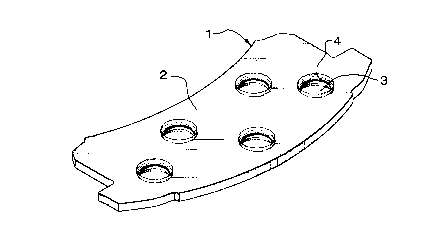
Fig. 1 shows a disc brake backing plate 1 of a conventional shape and thickness
20 (1/8 to 1/2 of an inch), made preferably from metal or a metal composite adapted to withstand the
rigors of a conventional disc braking system. The backing plate has a first surface 2 on which a
friction pad 9 (shown in Fig. 5) is to be mounted by a conventional molding process. Any
suitable number of preferably circular holes 3 are defined within the backing plate. Each hole
CA 022~l4~2 l998-l0-22
has a wall 4.
As best seen in Fig. 4, the wall is sloped such that the area of each hole at the
first surface is smaller than the corresponding area at the second surface 5. A section 10 of the
wall preferably has a rough surface which facilitates a strong bond with the friction pad during
5 the molding process. A ridge 6 protrudes outwardly from the first surface surrounding each
hole. The inner side 7 of the ridge facing the hole is rounded to permit the friction pad material
to flow easily into the hole. The outer side 8 of the ridge facing away from the hole has a rough
surface and projects outwardly, generally perpendicular to the first surface 2.
Fig. 2 shows the first step in the process of manufacturing the backing plate
0 according to the present invention. A generally round raised section 15 is formed on the first
surface 2 of the backing plate 1 by any suitable means, such as, for example, being cold-
formed by driving a first punching tool 16 into the second surface 5 of the backing plate. The
impact surface at the distal end 17 of the first punching tool preferably has a generally
hemispherical shape in order to produce a circular ridge and hole.
Fig. 3 shows the final step in the process according to the present invention. A
hole 3 (shown in Fig. 4) is formed by any suitable means, such as, for example, being cold-
formed by driving a second punching tool 18, having a generally cylindrical impact surface at its
distal end 19, into the raised section 15 of the backing plate 1 with sufficient force to create the
hole. As shown in Fig. 4, a ridge 6, as described above, remains on the first surface 2 of the
20 backing plate surrounding the hole. Because the ridge is preferably conserved from material
that would otherwise form part of the slug punched out of the backing plate, the structural
strength of the backing plate, according to the present invention, is increased 10-20% from
backing plates manufactured by prior art processes.
CA 022~l4~2 l998-l0-22
The shape of the second punching tool is configured and the force of the impact
is applied in such a way that a smooth shear section 20 is formed on the section of the wall 4
adjacent to the first surface 2, followed by a rough section 10, as described above. The shape
of the second punching tool and the force of the impact also provides the slope in the wall, as
described above.
Testing has indicated that the required bonding strength is obtained at minimal
cost and while maintaining the required structural strength for the backing plate, by punching
preferably four holes 3 with an average diameter of ranging from 318-3/4 Of an inch. The diameter
of each hole at the second surface is 10-15% larger than the corresponding diameter at the first
0 surface. The optimal range for the width of the ridges 6 surrounding each hole is 0.04-0.12
inches and the optimal range for the height of the ridges is 1/16-1/8 Of an inch. The optimal
curvature range to facilitate flow of the pre-form material into each hole is a curvature radius of
0.04-0.12 inches. It will be understood by those skilled in the art that these dimensions and
numbers of holes may be varied, and such variations are within the scope of this invention.
During the molding process (not shown) to attach the friction pad, the pre-form
material flows around each ridge 6 and into each hole 3. The rounded side 7 of each ridge
facilitates the flow of the pre-form material into each hole. After the pre-form material solidifies
and a bond with the backing plate is formed, as best shown in Fig. 5, the widening of each hole
toward the second surface 5 provides improved tensile strength, while the outer, upwardly
20 projecting side 8 of each ridge provides improved shear resistance. These improvements are
accomplished using a two step process, and without the need of adding additional features,
such as bosses or knobs, leading to a decreased manufacturing time and significant cost
savings.
CA 022~14~2 1998-10-22
It will be appreciated that the above description relates to the preferred
embodiment by way of example only. Many variations on the invention will be obvious to those
knowledgeable in the field, and such obvious variations are within the scope of the invention as
described and claimed, whether or not expressly described.