Note: Descriptions are shown in the official language in which they were submitted.
CA 02251658 1998-10-09
WO 97/38635 PCT/L1596/18605
1
SURGICAL CUTTING DEVICE REMOVABLY CONNECTED
TO A ROTARY DRIVE ELEMENT
Background of the Invention
This invention relates generally to devices used in surgical procedures, such
as, for
example, endoscopic diskectomy and endoscopic spinal fusion. More
specifically, the invention
relates to a rotatable surgical cutting device which is removably connected to
a rotary drive
element.
Field of the Invention
In the United States, spinal disk problems are the most common cause of
disability of
people under 45 years of age. There are currently 5.2 million Americans either
temporarily or
permanently disabled as a result of chronic back pain. Approximately 220,000
spinal operations
are performed in America each year to combat the disabilities caused by spinal
disk problems.
A common problem among patients suffering from chronic back pain is a
protruding
lumbar intervertebral disc. This condition occurs when a portion of the disk
protrudes into the
spinal canal space and creates pressure on a nerve. A patient may also
experience a partial or
complete collapse of an intervertebral disk, resulting in spinal instability,
immobility and severe
chronic pain.
It is often necessary to surgically remove offending disk material from the
spinal canal to
improve the spinal function of the patient and to relieve chronic pain. In
some cases it is also
necessary to perform a spinal fusion, to improve spinal stability and to
provide additional support
for any damaged intervertebral disk.
Procedures such as endoscopic diskectomy can be used for the removal of
fibrous
intervertebral tissue. Endoscopic surgeries are accomplished by creating small
openings or
"ports" in the body, through which various small instruments or a camera may
be inserted and
manipulated to observe or work in the disk space area. Current endoscopic
procedures utilized
for the removal of disk material rely primarily upon automated or manual
methods. (Surgical
Dynamics Nucleotome or the Soframor-Danek Diskector). These methods remove
intervertebral
disk material by using a guillotine cutting blade, with the aspiration of disk
material into a port
connected to a cannula, once the device is activated.
For open spinal fasions, products currently available for the removal of
intervertebral disk
tissue include the Acromed manual PLIG instrumentation and the Cloward PLIF
set
instrumentation. These instruments are manual in operation and utilize rasps
and rongeurs,
whereby disk material is removed by increasing the size of the rasp
sequentially.
-1-
CA 02251658 2005-05-19
Based upon the current instrumentation and procedures available for the
removal of intervertebral disk material and the preparation of bone graft
sites,
there remains an opportunity to improve the speed, accuracy and
effectiveness of these procedures. In addition, animal studies have indicated
that circular holes in the intervertebral disk space provide an improved
response to healing over those that are square, rectangular, or cruciate in
shape. Therefore, an opportunity exists for the introduction of a device that
will provide a smooth circular void in the intervertebral disk space, allowing
for improved healing of the annular opening.
~o Also due to the tenacious adhesion of the disk material to the vertebral
end plate, an opportunity exists for a more efficient and effective method of
removing disk material from the area of the vertebra in preparation for bone
grafts.
Lastly, there remains an opportunity to reduce the amount of trauma
suffered by the patient during back surgery, as the result of instrument
movement and manipulation in and around the spinal canal and
surrounding pathology.
Summary of the Invention
2o In accordance with one embodiment of the present invention there is
provided a cutting device for removing tissue matter from a surgical site
during a surgical procedure, which comprises: means for emulsifying the
tissue matter during a surgical procedure; the emulsifying means including a
cutting head having an entry tip dimensioned to facilitate entry of the
cutting
head within the tissue matter and two cutting blades, and defining an axis
about which the cutting head rotates, each cutting blade positioned with
respect to the axis to define a window extending through the cutting head,
each cutting blade defining a leading cutting edge adapted to cut the
tissue matter upon rotation of the cutting head in one direction of rotation,
3o the cutting blades dimensioned and configured to generally direct tissue
portions cut by the cutting edges to the window of the cutting head whereby
-2-
CA 02251658 2005-05-19
the cut tissue portions are at least partially emulsified upon continued
rotation
of the cutting head, each cutting blade defining an interior wall portion
extending continuously at a fixed angle from the leading cutting edge
substantially through the cutting head; and means for rotatably supporting
the emulsifying means during the surgical procedure.
In accordance with another embodiment of the present invention
there is provided a surgical cutting device for emulsifying matter from a
surgical site comprising: a cutting head having an entry tip adapted to
facilitate entry of the cutting head into tissue matter and two substantially
~o rigid, autonomous cutting blades, each cutting blade located on opposed
edges of a window extending through an interior portion of the cutting head
such that each cutting blade forms a leading edge adapted to cut and
emulsify the tissue matter in the same direction of rotation, each cutting
blade defining an interior wall portion extending continuously at a fixed
angle
from the leading edge substantially through the cutting head; and a shaft
connected to the cutting head for mounting the cutting head to a rotary
surgical drill.
Yet another embodiment of the present invention provides a surgical
cutting device comprising: a shaft connectable to a rotary surgical drill and
2o defining a longitudinal axis; a cutting head mounted to the shaft for
cutting
and reducing tissue matter; the cutting head including an entry tip and two
cutting blades, each cutting blade arranged about the longitudinal axis to
define a window extending through the cutting head, the cutting blades
having interior wall portions disposed adjacent the window, each interior wall
portion arranged at a predetermined angle with respect to the longitudinal
axis and extending continuously substantially through the cutting head at the
predetermined angle to terminate in a leading cutting edge, the leading
cutting edges adapted to cut and emulsify tissue matter upon rotation of the
cutting head in one direction of rotation.
so A still further embodiment of the present invention provides a surgical
cutting device for emulsifying matter from a surgical site, comprising: a main
-3-
CA 02251658 2005-05-19
shaft defining a longitudinal axis; a mounting shaft positioned at one end of
the main shaft, the mounting shaft having a diameter adapted for insertion
into a surgical drill; and a cutting head positioned at another end of the
main
shaft opposite the mounting shaft, the cutting head having an entry tip and
first and second cutting elements arranged about the longitudinal axis to
define a window extending through an interior portion of the cutting head,
each cutting element defining a leading cutting edge adapted to cut in the
same direction of rotation and being located on an opposed edge of the
window, and having an angled wall extending continuously from the leading
~o cutting edge substantially through the cutting head at a predetermined
angle, the angled wall dimensioned to facilitate directing of tissue portions
cut by the cutting elements into the window whereby the cut tissue portions
are at least partially emulsified upon continued rotation of the cutting head.
In accordance with a still further embodiment of the present invention
there is provided a cutting device for emulsifying a variety of different
types
of matter from a surgical site during a surgical procedure comprising: means
for emulsifying the variety of different types of matter during the surgical
procedure; the emulsifying means including an entry tip adapted to provide
an entry of the cutting head into the variety of different types of matter to
be
2o cut by the cutting head and two hardened, autonomous, stand alone
cutting blades, the cutting blades each having an interior wall arranged at a
fixed angle relative to a central bisecting plane extending between the
cutting blades and extending continuously substantially through the cutting
head at the fixed angle, the interior walls defining a window therebetween
such that each cutting blade defines a leading edge adapted to cut
through the variety of different types of matter it encounters through
3b0° in
the same direction of rotation; and means for rotatably supporting the
emulsifying means during the surgical procedure.
In accordance with another embodiment of the present invention
so there is provided a cutting device for removing matter from a surgical site
during a surgical procedure comprising: means for emulsifying the matter
-3a-
CA 02251658 2005-05-19
during the surgical procedure; the emulsifying means having a center of
gravity located at a central axis extending along a length (hereof and
comprising an entry tip and a cutting blade on opposed leading edges of a
window extending through the emulsifying means; and means for rotatably
supporting the emulsifying means during the surgical procedure.
In accordance with yet another embodiment of the present invention
there is provided a cutting device for removing matter from a surgical site
during a surgical procedure comprising: means for emulsifying the matter
during the surgical procedure; the emulsifying means comprising an entry tip
~o and a cutting blade on opposed leading edges of a window extending
through the emulsifying means; means for rotatably supporting the
emulsifying means during the surgical procedure; and a guard for sliding onto
a collet of a drill, the guard having an opening extending along a length
thereof for insertion of the supporting means.
The invention, in preferred embodiments, is a surgical cutting device
constructed from one piece of hardened surgical steel. The device has a
proximal end comprising a mounting shaft, a main shaft, and depth
indicators located on the main shaft. The cutting head is positioned at the
end of the main shaft at the distal end of the device.
2o The mounting shaft is designed to fit into any standard low or high
speed rotary surgical drill. The cutting device is attached to and removable
from the rotary drill in the same manner as currently available rotary tools
and
accessories, namely by placing the mounting shaft into the friction lock
collet
of the drill. The main shaft of the cutting device is designed in various
lengths
to enable the use of the device for both cannulated endoscopic surgeries, or
non-cannulated open back surgeries. The depth indicators provide a
method for the instantaneous observation of cutting depth when the device
is in the intervertebral disk space. These indicators also serve to alert the
surgeon to over-penetration into the disk wall.
so In preferred embodiments, the cutting head of the device includes two
cutting blades and an entry tip. The two-bladed configuration of the cutting
-3b-
CA 02251658 2005-05-19
head forms a window between the cutting blades providing an area for
removed disk material to accumulate and be further reduced in density.
The cutting head of the device is designed with various outside
diameters and tip configurations. The various head diameters allow for the
device to be used for the removal of disk material in the cervical, thoracic
or
lumber regions of the spine, based upon the pathology and intervertebral
disk space of the patient. The unique design of the head enables the smooth
and accurate entry of the device into the intervertebral disk space, while
simultaneously cutting and reducing the density of the removal intervertebral
fibro cartilaginous disc material. The head of the device is also designed to
perform decortication of bone if desired, either simultaneously or
independent to the removal of the disk material. Based upon the
requirements of the surgical procedure, the surgeon may select one or more
of the various tip configurations to perform the disk removal procedure. Also,
by using a series of incrementally increasing diameter heads, the surgeon
can accurately increase the size of the void created in the intervertebral
disk
space. This provides an evacuated disk space in preparation for a bone
graft.
The primary head configurations of the device can be round, teardrop,
2o bulb, or elliptical shaped and include a flat ended arrow style tip, a
conical
bullet style tip, an elliptical, circular, or rounded tip. The bullet and
arrow style
tips are designed to be used primarily for the initial entry into the
intervertebral
disk space. These tips provide a smooth entry into the annulus of the disk, to
begin the intervertebral disk tissue removal process. The rounded tip is
designed primarily to be used in a secondary operation, to increase the
amount of disk material removed and to provide a smooth circular void in
the disk. The round tip may also be used for the decortication of bone if
desired. Based upon the procedure to be performed, the location of the
injury and the position of the offending disk tissue, the surgeon will select
the
so device head configuration, entry tip style and diameter accordingly.
In particularly preferred embodiments of the invention, the emulsifying
- 3c -
CA 02251658 2005-05-19
means or cutting head has a center of gravity located at a central axis
extending along a length thereof.
The device may be used in a cannulated or non-cannulated fashion,
based upon the surgical procedure to be performed. For an endoscopic
surgical procedure, the device is used in a cannulated fashion using a
standard surgical cannula and is designed to fit in most surgical cannulas
currently available.
In the case of endoscopic surgeries, the device is placed through the
skin and docked on the edge of the intervertebral disc. Once docked, the
~o surgeon uses the surgical drill to rotate the head of the device to
smoothly
enter the annulus of the disc. As the device enters into the disk space, the
disk tissue is cut and migrates to the elliptical opening at the center of the
cutting head. As the procedure continues, the removed disk material is then
further reduced in density, as a result of the spinning of the cutting blades.
The surgeon may then use the device to decorticate the vertebral end
plate in preparation for a bone graft, using the same, or a different device
diameter or tip configuration. Due to the reduction in density of the removed
disk material, normal surgical irrigation and suction can be used to
thoroughly
flush the surgical site. Since the density of the disk material is reduced to
an
2o emulsion, rather than being trimmed or cut into fragments, the possibility
of
disk debris being left at the operation site is significantly reduced.
When used in open back surgery, the device is used in a non-
cannulated fashion, utilizing a guard. In the case of these surgeries, the
device is used to remove disk tissue and decorticate
-3d-
i
CA 02251658 2004-09-14
bone externally from the cannula, in the same manner as described above for
endoscopic procedures.
In addition to spinal related surgeries, the surgical cutting device of the
present invention is also applicable to other surgical procedures. For
example, in
hip surgery, the device can be used for the removal of soft tissue and the
decortication of bone. In hip joint revision surgery, the device can be used
for the
removal of soft tissue, the decortication of bone and the removal of bone
cement.
In shoulder and shoulder joint replacement surgery, the device is also
applicable
for the removal of soft tissue and the decorication of bone. In knee surgery
and
knee joint replacement surgery, the device can also be used for the removal of
soft tissue and the decortication of bone. In all types of surgeries, the
device will
be attached to a rotary drill and operate similarly to that in spinal surgery.
Additional procedures for which the device may be used include, but are
not limited to, the micro lumbar laminectomy, the anterior or posterior inter-
body
lumbar diskectomy and fusion, the cervical anterior diskectomy and fusion and
the anterior thoracic diskectomy and fusion.
Accordingly, some features of this invention, according to preferred
embodiments, are to provide a surgical cutting device capable of providing a
circular hole in the intervertebral disk space for efficient disk removal
during
diskectomies and in preparation for bone grafting; provide a surgical device
with
the ability to accurately remove and reduce the density of intervertebral
fibro
cartilaginous disk material, and therefore reduce the possibility of disk
debris
being left in the intervertebral space. This removal of disk material improved
bone graft contact and will improve fusion potential; and to minimize the
degree
of tissue trauma; by reducing the elapsed time and tool manipulation currently
required to remove disk material and to prepare a site for bone grafting.
Additional advantages of the present invention will also become apparent
from the accompanying detailed description and drawings.
4
CA 02251658 1998-10-09
WO 97/38635 PCT/US96/18605
1
Brief Description of the Drawings
FIG. 1 is a top view of a typical cutting device;
FIG. 2 is a side view of the cutting device of FIG. 1;
FIG. 3 is a partial detail view of the cutting device of FIG. 1 illustrating
the cutting head,
including the angled blade configuration and the entry tip;
FIG. 4 is a cross-sectional view of the cutting head taken along line 4-4 of
FIG. 3;
FIG. 5 is a top view of a cutting device having an arrow style entry tip
configuration;
FIG. 6 is an end view of the cutting device of FIG. S.
FIG. 7 is a side view of the cutting device of FIG. 5;
FIG. 8 is a top view of cutting device having a bullet style entry tip
configuration;
FIG. 9 is an end view of the cutting device of FIG. 8;
FIG. 10 is a side view of the cutting device of FIG. 8;
FIG. 11 is a top view of cutting device having a elliptical style entry tip
configuration;
FIG. 12 is an end view of the cutting device of FIG. 11;
FIG. 13 is a side view of the cutting device of FIG. 11;
FIG.14 is a top view of the cutting device of FIG. 1 illustrating the
approximate length
of the device for use in a non-cannulated open back surgical procedure;
FIG. 15 is a top view of the cutting device of FIG. 1 illustrating the
relational length of
the device for use in a cannulated endoscopic surgical procedure;
FIG.16 is a top view of a alternative embodiment cutting device having a
rounded style
entry tip configuration;
FIG. 17a is a side view of a drill guard for use in an open back surgical
procedure;
FIG. 17b is a side view of a drill guard for use in an endoscopic surgical
procedure;
FIG. 18 is a side view of a self aspirating embodiment of the cutting device
of FIG. 1;
FIG. 19a is a top view of a round cutting head configuration of the cutting
device;
FIG. 19b is a top view of a bulb cutting head configuration of the cutting
device;
FIG. 20 is an end view of the cutting head of FIG. 19b having a rounded style
entry tip
configuration;
FIG. 21a is a top view of a cervical version of the cutting device;
FIG 21b is a side view of the cutting device of FIG. 21 a; and
FIG. 22 is a top view of a cutting device illustrating an alternate shaft
configuration.
Detailed Descri tn ion
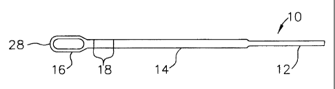
Referring to FIGS. 1 and 2, the surgical cutting device 10 of the present
invention is
shown. The surgical cutting device comprises a mounting shaft 12, a main shaft
14 attached to
-5-
CA 02251658 1998-10-09
WO 97/38635 PCT/US96/18605
the mounting shaft, and a cutting head 16 positioned at the opposite end of
main shaft 14. The
main shaft also includes engraved depth indicators 18 positioned on the main
shaft adjacent to
the cutting head. The cutting head, main shaft, and mounting shaft are an
integral piece of
hardened surgical steel, wherein the mounting shaft is connected to a rotary
drill so that the
cutting device can be rotated allowing the cutting head to operate.
Referring to FIGS. 3 and 4, the components of the cutting head 16 are shown in
greater
detail. The cutting head includes a window 20 machined through the cutting
head defining two
cutting blades 22 on a leading edge of the cutting head as the cutting device
is rotated in a
counterclockwise direction 24. Window 20 is machined through the cutting head
defining angled
walls 26 through the depth of the cutting head. Walls 26 are at an angle a
approximately 15-30 °
from a horizontal plane extending perpendicular to the opening of the window.
The cutting
blades can be smooth as shown in FIG. 3 or serrated. Window 20 provides an
area for removed
tissue to accumulate and be further reduced in density, due to the rotation of
the cutting blades.
The removed material is essentially liquified and removed by aspiration. It is
to be understood
that for a cutting device rotatable in a clockwise direction, the
configuration of the cutting blades
and tapered walls would be a mirror image of that depicted in FIG. 4. The
window 20 as shown
in FIGS. 1-4 is elliptical or oval in shape, however, other shaped windows are
contemplated as
discussed subsequently herein.
Another important aspect of the cutting head is the entry tip configuration
28. FIGS. 5-7
illustrate an arrow style entry tip 30 for the cutting device 10. The arrow
style entry tip has an
elliptical perimeter 32 with a converging sloping surface 34 which converges
in a rounded point
36. FIGS. 8-10 illustrate an alternative entry tip configuration being a
bullet style entry tip 38.
Bullet style entry tip includes a circular outer perimeter 40 having a sloping
converting surface
42 terminating in a rounded point 44.
FIGS. 11-13 illustrate a second alternative entry tip configuration being an
elliptical style
entry tip 46. Elliptical style entry tip 46 includes an elliptical perimeter
48 with an arcuate
rounded outer surface S0.
The cutting device of the present invention has dimensions that are practical
for entry into
the spinal intervertebral disc space for the various regions of the spine. The
typical outside
diameter or width of the cutting head will range from about 3 to about 13
millimeters. Widths
of the cutting head can also range from about S to about 9 millimeters. The
cutting head is
balanced around the axis of the device so that the device will not wobble
during rotation.
As seen best in FIG. 14, the typical length of the cutting device 10 of the
present invention
for use in a non-cannulated fashion is from about 3 inches to about 6 inches.
This length
provides the necessary shaft length for insertion into a surgical drill and
drill guard. The
-6-
CA 02251658 1998-10-09
WO 97/38635 PCT/CTS96/18605
mounting shaft 12 of the cutting device has a reduced diameter from the main
shaft 14 for
insertion into the surgical drill collet 52.
S FIG. 15 illustrates the typical length of the cutting device for use in a
cannulated,
endoscopic fashion and is from about 8 inches to about 12 inches. This length
provides the
necessary main shaft 14 length for insertion into the surgical drill and a
standard surgical cannula
(not shown) and provides the necessary extension of the entry tip 28 from the
cannula for entry
into the intervertebral disc. The outside diameter of the cannulated
endoscopic device is that
necessary to fit in close tolerance with the inside diameter of a standard
surgical cannula.
The length of all embodiments of the cutting device of the present invention
typically
could increase in increments of 1 /2 inch. The mounting shaft diameter 12
typically would be
0.092 inches or 0.125 inches based upon currently available surgical drill
mounting collets 52.
FIGS. 17a and 17b illustrate standard surgical drill guards, wherein FIG. 17a
depicts an
open back surgery drill guard 54 and FIG. 17b depicts an endoscopic surgery
drill guard 56. The
difference between drill guards 54 and 56 is the overall length of the guard.
Guards 54 and 56
are made of surgical steel tubing that slides onto the collet 52 of the drill
and is held in place by
friction. More specifically, guards 54 and 56 include a friction sleeve 58
which slides over the
drill collet 52. Drill guards 54 and 56 further include a finger pull 60 for
insertion and removal
of the drill guard and a guard body 62 extending from the finger pull 60. A
stabilizer bushing
64 is positioned at the end of the guard body 62. A shaft opening 66 extends
along the length of
the guard for insertion of the cutting device. Vent holes 68 are typically
located along the length
of the guard body 72 at given intervals. Standard commercially available
guards or custom made
guards that are slightly longer and have a slightly larger internal diameter
may be used with the
cutting device of the present invention.
FIG. 18 illustrates a self aspirating cutting device 70 which includes an
aspiration channel
72 extending along the length of the mounting shaft 74, main shaft 76 and
terminating at window
80 in cutting head 78. The aspiration channel terminates in openings 82 and
84, in the window
of the cutting head and in the mounting shaft, respectively. The aspiration
channel of the cutting
device is for aspiration of the removed material.
The geometrical shape of the cutting head can also be varied. The cutting head
16 of the
cutting device embodiments referenced herein illustrate a generally elliptical
cutting head.
Alternative cutting head geometries can be seen in FIGS. 16, 19a and 19b. FIG.
16 illustrates a
tear drop cutting head configuration 86 having a rounded entry tip 88 and
includes converging
walls 90 extending from entry tip 88 to main shaft 92. In the tear drop
configuration the cutting
head includes a tear drop shaped window 94. Figure 19a illustrates a round
cutting head
configuration 96. In this configuration the cutting head includes a rounded
outer wall 98
_7_
CA 02251658 1998-10-09
WO 97/38635 PCT/US96/18605
1
extending from the main shaft 100. The round cutting head also includes a
circular window 102.
FIG. 19b illustrates a bulb cutting head configuration 104 having a rounded
entry tip 106 and
generally parallel side walls 108. Converging back walls 110 extend from the
main shaft 112 to
the parallel side walls 108. The bulb cutting head configuration includes a
generally elliptical
or oval window 114. In each of the tear drop cutting head configuration, round
head
configuration, and bulb head configuration, the entry tips have a rounded
configuration as shown
in FIG. 20. The rounded entry tip includes an oval perimeter 1 i6 and a
rounded outer surface
118.
Although the present invention has been described and is illustrated with
respect to various
embodiments thereof, it is to be understood that it is not to be so limited,
since changes and
modifications may be made therein which are within the full intended scope of
the invention as
hereinafter claimed. For example, FIGS. 21 a and 21 b illustrate a cervical
cutting device 120
wherein the mounting shaft 122 and main shaft 124 are of equal diameter. The
cervical cutting
tool preferably would have an overall length of 2.75 inches and a cutting head
diameter of 0.125
inches. As seen in FIG. 21b, the height of the cutting head 126 is equal to
the diameter of the
main shaft.
FIG. 22 illustrates yet another alternative cutting device 128 having a
tapered main shaft
130 without fillets at the juncture between the main shaft and the mounting
shaft 132. Cutting
device 128, by having a tapered main shaft, provides a design having improved
strength and
rotational stability for longer shaft lengths.
30
_g_