Note: Descriptions are shown in the official language in which they were submitted.
CA 02251698 1998-10-14
WO 97/39583 PCT/US97/06216 _
1
A Method and System to Transmit Video/Data Signals from a
Device to a Communications Network Connection Card
1o
Technical Field
The present invention relates to the field of video and data
communications, and in particular, relates to the field of video and data
signal transmission from a device or a broadband communications
module to a communications network and/or a communications network
connection card.
Background of the Invention
Consider this example: You are home, laid out flat with bad
back trouble. The only thing that keeps your flagging spirit from
sinking is the pay-per-view movie showing on your television through
the paid courtesy of your cable television (CATV) service provider. The
movie has ended, but it is the first of a trilogy and you would really like
to order and watch the sequels. But this is a Herculean task to
accomplish. With your bad back, it is going to be a lot of trouble to get
out of bed, to find the telephone, to remember and to dial the pay-per
view telephone number, and to get yourself back into the least
uncomfortable position that your back will allow for more movie
watching.
Wouldn't it be nice if you could just use a remote control
unit with your television to request the delivery of the second and third
movie? So, what is the hang up? The hang up is that no cost effective
transport system exists for the transmission of signals from a device
(such as your set top box) to a signal destination (such as your CATV
service provider, video server, etc.) so that you could order your next
movie by simply using the remote control unit. Those skilled in the art
CA 02251698 1998-10-14
WO 97/39583 PCT/US97/06216 _
2
will recognize the term "set top box" as referring to those elements of
the device (whether disposed within a set top box or not) that serve as an
interface system between the device and the fiber-and-coax network that
transports the signals.
To understand the problems associated with ordering a
movie through use of your television's remote control unit, a general
description of CATV service is provided by reference to Fig. 1. Fig. 1
is a block diagram of a video signal delivery system. Generally, the
delivery or transmission of a set of video or data signals from a video
signal source (such as a CATV service) to a device (such as your set top
box) is referred to as "downstream" delivery, a "downstream path" or a
"forward path". As illustrated in Fig. l, a downstream path 5 generally
has its beginning at a video signal source 10 that transmits a set of video
signals to an optical transmitter 12. For ease of explanation, the term
"optical transmitter" is used herein to encompass the elements or
mechanisms that receive the video signals from the video signal source
10, that convert, modulate, carry, amplify and/or split the video signals
(as necessary) so as to optically transport the signals from the video
signal source 10 to one or more local distribution units such as
broadband communications module 14. A broadband communications
module is also referred to as an analog video unit, an analog network
unit, an optical receiver, or in some cases, as an optical node. A
broadband communications module 14 typically converts the video
signals from optical to electrical, and transmits the video signals through
a bandpass filter 15 over coaxial cable to a relatively large number of
devices. One such device is device 16 which is also referred to as a set
top box, home controller unit, cable ready TV, or residential gateway.
The transmission of a set of video signals from a broadband
communications module 14 over coaxial cable to a device 16 is referred
to as a "drop". Thus, Fig. 1 illustrates a downstream path 5 for the
transmission of a set of video signals from a video signal source 10, to an
optical transmitter 12, to a broadband communications module 14, to a
filter I S and for ultimate drop to a device 16. The downstream path 5
has been generally described in the context of the delivery of a movie to
a subscriber's television, but the description is applicable as well to other
video or data signal delivery such as broadcast television, or video, near
video on demand, InterNet access, interactive shopping and similar
CA 02251698 1998-10-14
WO 97139583 PCT/US97/06216 _
3
delivery services. For example, a video signal source may include a
video server, modulator, headend or a content provider. A device may
include a personal computer, set top box, digital receiver, home
controller terminal or gateway.
Generally, the delivery or transmission of a set of video or
data signals from a device to a video/data signal destination is referred to
as "upstream" delivery or a "return path". As illustrated in Fig. 1, a
return path 20 generally has its beginning at a device 16 that transmits a
set of video or data signals over coaxial cable to a bandpass filter 15.
Typically, the filter recognizes the signals as return path signals, and
transmits the signals to other elements or mechanisms for ultimate
delivery to their destination. As will be discussed in more detail below,
Fig. 1 illustrates a return path 20 for the transmission of a set of video
signals from a device I6, to a filter 15 (with return path amplification)
to a Fabry-Perot return path laser 22, to a return path concentrator 24,
to a central processing station 26, and for ultimate delivery to a
video/data signal destination 28. The return path 20 has been generally
described in the context of the order of a movie from a subscriber's
television, but the description is applicable as well to other video or data
signal delivery from a source such as video channel selection, impulse
pay per view requests, shopping requests, and enhanced video control
signals for stopping, reversing or accelerating the playback of a video or
data source.
In the above description of a downstream path 5 and a
return path 20, reference was made to elements such as the video signal
source, etc., but the actual mechanism for transporting the video or data
signals among the elements was not spelled out in all cases. This
omission was deliberate so as to provide a little historical discussion at
this point. In the early days of cable television, CATV service providers
used coaxial cable as the mechanism for transporting the video signals
from the video signal source to the device. Fence, the term "cable
company". But coaxial cable has its limitations as a transport
mechanism, and cable companies soon realized the advantages offered by
fiber optics to the transport of video signals. Most CATV service now is
provided over a fiber-and-coax network, which is a hybrid network that
provides duplex voice and data circuits and simplex broadband channels
to the public. Optical fibers are used for signal transport from a video
CA 02251698 1998-10-14
WO 97/39583 PCT/US97/06216 _
4
signal source to local distribution points such as the illustrated broadband
communications module 14. At such a local distribution point, the signal
streams are converted from optical signals to electrical signal streams,
and distributed ("dropped") to individual homes over shared coaxial
cable.
CATV service providers recognized the potential of fiber
optics for the transport of video/data signals and provided fiber-and-coax
networks for the downstream path of delivery of video signals. But, for
the most part, CATV service providers have until recently ignored and
failed to provide a signaling return path for video/data signals. The
fiber-and-coax networks generally were not set up to handle video/data
signals that were transmitted from a device 16 (such as your set top box)
back through the optical transmitter I2 to the video signal source 10.
One reason that CATV service providers (and others) ignored the
signaling return path is that, until recently, there was little possibility
that a subscriber would have information to transmit by return path. In
its early days, CATV was developed for subscribers who lived outside
the reach of over-the-air broadcast television stations. These early
subscribers paid a flat fee for service. No signaling return path was
necessary.
Another reason that CATV service providers (and others)
ignored the return path is based on economics. Alterations or additions
to a fiber-and-coax network to provide a signaling return path have not
been cost justified for several reasons. For example, the proposed
alterations and additions would be extensive and expensive. Further,
until recently, it has been believed that even with "pay-per-view
services" a subscriber would have only a small amount of information to
transmit by return path. Thus, the cost did not justify the changes that
were necessary.
But times have changed. The personal computer has
changed the attitude of the public. Surveys have demonstrated that the
majority of Americans cannot imagine living without a personal
computer. Through a personal computer, a user has access to alI sorts of
information. Through mechanisms such as local area networks, wide
area networks, the InterNet, and others, a user is able to interact with
others who are in the network and to interact with computer programs,
information and services. In other words, with a networked computer, a
CA 02251698 1998-10-14
WO 97/39583 PCT/L1S97/06216 _
user has a "downstream path" for the receipt of information, and a
"return path" for the transmission of information. Having been educated
by networked computers to the advantages of the exchange of
information, a user is surprising dismayed to find that CATV service
5 generally is only "one-way", i.e., downstream path only. There is no
convenient, efficient, economical return path. How Neanderthal!
Within the next few years, the need for multichannel, bi-
directional video/data transmissions will multiply within every home and
enterprise because of the coming integration of video/data information
into the conduct of business, the process of learning and other aspects of
life in the twenty-first century.
Synchronous Return Path S, sv tem
At least one company has given some thought to the
provision of a signaling return path in a fiber-and-coax network:
Synchronous Group, Inc., San Jose, California. Synchronous has a
return path system that includes a product known as a single home
receiver or a multiple dwelling unit receiver. The Synchronous system
is explained in connection with Fig. 1. Generally, in the Synchronous
return path system, a set of analog video/data signals are received from
the device 16, converted from electrical to optical signals, and
transmitted to the video/data signal destination 28. If necessary, the
signals are converted from analog to digital only at the video/data
destination 28 or as a relatively last step in transmitting the signals to the
video/data destination 28.
More particularly described, the Synchronous return path
system works in conjunction with standard equipment provided in
connection with mechanisms that accommodate CATV service. For
example, a device (such as your set top box) is typically equipped with a
radio frequency modem that outputs digital signals with an analog
modulated bit stream in quaternary phase shift keying (QPSK) or similar
format. Typically, the modem is part of the set top box.
In the return path, the signals come out of the set top box at
a frequency between five to forty MHz on the coaxial cable drop to a
filter 15. In Fig. 1, filter 15 is shown as a separate block from the
broadband communications module 14, but generally, the filter is
incorporated as part of such a module 14. At the broadband
CA 02251698 1998-10-14
WO 97/39583 PCT/US97/06216
6
communications module, signals from hundreds of devices may be
combined and amplified. Typically, the amplification is carried out at a
return path amplifier (not illustrated). This combination and
amplification leads to the introduction of a lot of noise, thereby
distorting the signals. As illustrated in Fig. 1., after the signals are
combined and amplified, they are transmitted to a Fabry-Perot return
path laser 22. The laser is used to convert the combined signals from
electrical to optical signals. It would be extremely uneconomical to
provide a fiber for the transport only of these combined converted
signals received from just the device 16 or group of devices served by a
single broadband communications module 14. Thus, to lessen the cost of
return path system, the converted combined signals are generally
modulated and are passed to a return path concentrator 24. At the return
path concentrator 24, the converted, combined and modulated signals are
further modulated with all of the signals that have been sent for
transmission along the return path at that time. These signals are
modulated into 55-600 MHz of spectrum and transmitted to the central
processing station 26. At the central processing station 26, the signals
are converted from optical to electrical signals and are demodulated into
their respective five to forty MHz bandwidths. After this demodulation,
the signals are provided to their respective video/data signal destinations.
At this point, the signals also may be converted from analog to digital.
One destination may be a local area network such as a selected EtherNet.
In that case, the signals may be routed to an EtherNet card for
connection and routing pursuant to an EtherNet protocol to a further
destination.
Synchronous Group is to be commended for its foresight in
developing a return path system. But this system has drawbacks. As
noted, the combination of quite a few sets of video signals leads to the
introduction of noise and results in signal distortion. Electronics must be
provided to adjust and to compensate for the noise. These electronics
themselves may present trouble by the introduction of noise, by error,
by malfunctions, etc. Needless to say, such electronics may be expensive
to design and engineer, to install, to set up to work optimally, to
maintain, and to replace. Thus, these electronics may effectively raise
the cost of a broadband communications module and its use above the
level that the market may bear for return path services.
CA 02251698 1998-10-14
WO 97/39583 PCT/US97I06216
7
Another drawback of the Synchronous return path system is
the use of the Fabry-Perot return path laser. Such a laser is relatively
expensive in the context of return path CATV services for small
numbers of subscribers. If such a laser is necessary for each broadband
communications module, then the Synchronous system is too expensive
for commercial use. As further drawbacks to the Synchronous system,
the same criticisms leveled at the system in connection with the possible
trouble, expense, maintenance, repair and adjustment of the extra
electronics in the broadband communications module may be said in
0 connection with the use of the Fabry-Perot return path laser 22, the
return path concentrator 24 and extra or adjusted elements necessary to
accommodate the Synchronous system in each central processing station
26.
Further, another drawback of the Synchronous return path
system is that it requires demodulation of each of the individual 5-40
MHz return paths at some central location. This demodulation is
necessary before handoff to a local area network, wide area network or
EtherNet router. Demodulation costs are a big part of costs in a return
path system.
Another drawback of the Synchronous return path system is
that it is an analog transmission system. The signals from device 16 are
transmitted in analog form until nearly the end of their journey. Thus,
there is little possibility or opportunity for sampling the signals or
otherwise diverting them in a useful form for use with other systems
and/or elements. In other words, to deliver video/data signals along the
Synchronous return path system to a selected EtherNet destination, the
video/data signals must travel the entire return path from the device 16,
to the broadband communications module 14, the Fabry-Perot Return
Path laser 22, the return path concentrator, the central processing station
26, and only then to the selected EtherNet destination 28. Along the
way, the signals may be lost, distorted, etc.
Opportunities Presented by the Telecommunications S, s
As noted above, surveys have demonstrated that most people
cannot imagine living without a personal computer. An even greater
number of people, it may be assumed, cannot imagine living without the
telecommunications service they have come to expect. We are not just
CA 02251698 1998-10-14
WO 97/39583 PCT/US97/06216
8
talking telephones. We are talking about interactive lines of
communication including conventional telephone service, facsimile
service, integrated services digital network (ISDN), and other digital and
data services including EtherNet connections. We are talking about a
system that allows for the interaction between people, between people
and computers (or other mechanical devices) and between computers {or
other mechanical devices).
With the myriad communication possibilities that are
afforded through the telecommunications network, it is a significant
drawback that CATV services do not provide any kind of an economical
and practical connection to the telecommunications network. This is a
failing shared by the Synchronous return path system.
In summary of the background, CATV service is hampered
in the field of communications by its failure generally to provide a way
for a user to send information along a return path from the user's device
to a video/data signal destination. The Synchronous system offers a
return path for video/data signals, but only in a manner that includes
additional elements that add cost, installation, maintenance and failure
concerns to the system. Further, the Synchronous system has a
significant drawback in its transmission of the video/data signals in
modulated analog form along the return path. Accordingly, there is a
need in the art for a system that provides for a return path for the
transmission of video/data signals from a device to a video/data signal
destination. In particular, there is a need for a system that provides for a
return path that is relatively inexpensive to set up, that functions well
with a minimum of equipment and minimum of modification to standard
elements, and that is easy to maintain and service. Especially, there is a
need for a system that provides a return path that minimizes the impact
of noise on signal transmission. Further, there is a need for a system
3o that provides a return path so that a connection may be made to the
telecommunications or other communications network. Finally, there is
a need for a system that provides an interface system that converts analog
signals received through a coaxial cable interface from a device to digital
signals that are appropriate for communication with other networks such
as EtherNet.
CA 02251698 1998-10-14
WO 97/39583 PCT/US97/06216
9
Summary of the Invention
The present invention satisfies the needs in the art. Stated
generally, the present invention allows for a connection between: (1) the
downstream path of a video/data signal transmission system from a signal
source to a device; and (2) the return path from the device to a signal
destination. With this connection, the range of broadband services that
are available to a subscriber is greatly expanded. The present invention
allows for cost effective delivery of analog and digital video services and
integrated delivery of high bandwidth data communications and
telecommunications services.
Still stated generally, the present invention provides a return
path for the transmission of signals from a device to a signal destination.
This return path minimizes signal distortion. In the preferred
embodiment, an interface is provided so that the analog signals
transmitted over a coaxial cable interface from the device to a broadband
communications module are converted to digital signals. In digital form,
the signals may be further formatted as appropriate for further
communication with any wide bandwidth communications network. The
signals may be formatted in communications network connection format
for transmission to a communications network connection card such as
an EtherNet card. The signals also may be transmitted to an optical
network unit, thereby connecting the broadband communications module
to the systems that employ optical networks.
More particularly stated, a first embodiment of the present
invention is a signal transport system for the delivery of video signals to
a device, for the return of analog signals from the device, and for the
transmission of digital signals to a signal destination. This embodiment
includes a broadband communications module that receives video signals
from a signal source and delivers the video signals to the device. The
broadband communications module is further operative to receive analog
signals from the device, and to transmit the analog signals to an
interface. The interface receives the analog signals, converts the analog
signals to digital signals and transmits the digital signals to an optical
network unit. The optical network unit further transmits the digital
signals to a signal destination. In the preferred embodiment, the
broadband communications module includes an optical receiver that
receives the video signals from the signal source and transmits the video
CA 02251698 1998-10-14
WO 97/39583 PCT/US97/06216 _
signals to a filter. The filter transmits the video signals to a coaxial cable
interface, which in turn, transmits the video signals to the device. With
respect to the receipt of analog signals from the device, the broadband
communications module preferably includes a coaxial cable interface that
5 receives the analog signals from the device and transmits the analog
signals to the filter. The filter then transmits the analog signals to a
converter and the converter converts the analog signals to the digital
signals. Preferably, the converter formats the digital signals in a
communications network connection format, and the converter transmits
1 o the digital signals in the communications network connection format to a
communications network connection card. The communications network
connection card may be adapted for use in the optical network unit, and
may transmit the digital signals to an optical receiver/transmitter or a
communications network.
In addition, the present invention may include an alarm
monitoring system so that monitoring may take place of a radio
frequency output alarm or an optical signal alarm with respect to the
video signals delivered to the device. The present invention also may
include a control feature such as a turn-on feature or a turn-off feature
with respect to the video signals delivered to the device, whereby said
video signals may be, respectively, turned-on for delivery to said device,
or turned-off for delivery to said device. Further, the present invention
may include a drop test unit for testing the electrical characteristics of
the video signals or to conduct a continuity check with respect to the
video signals.
The present invention also provides an embodiment that is a
signal transport system for the receipt of analog signals from a device
and for the transmission of digital signals to an optical network unit.
This embodiment includes a broadband communications module to
receive analog signals from the device, and to transmit the analog signals
to an interface. The interface converts the analog signals into digital
signals, and transmits the digital signals to an optical network unit.
Preferably, in this embodiment, the interface is operative to convert the
analog signals into digital signals in a communications network
connection format and to transmit the digital signals in the
communications network connection format to a communications
network connection card. The interface may be adapted for use in the
CA 02251698 2002-O1-02
WO 97/39583 PC'T/LJS97/06216 _
11
broadband communications module as may be the communications
network connection card.
In addition, the present invention provides an embodiment
that is a signal transport system for receipt of analog signals from a
device and for the transmission of digital signals to a communications
network connection card. The system includes an interface that receives
the analog signals, that converts the analog signals into digital signals in a
communications network connection format, and that transmits the
digital signals in the communications network connection format to the
communication network connection card. The interface or the
communications network connection card may be adapted for use in the
device. Alternatively, the interface or the communications network
connection card may be adapted for use in a broadband communications
module. ,
In yet another embodiment, the present invention provides a
method for transmitting signals from a device to a communications
network connection card in a signal transport system. Pursuant to the
method, analog signals are received from the device, are converted to
digital signals in a communications network connection format, and
transmitted to the communication network connection card. Preferably,
in this method, video signals are delivered to the device from the signal
source. Further, a radio frequency output alarm or an optical signal
alarm may be monitored with respect to the video signals delivered to
the source, and the results of the monitoring reported to an alarm
monitoring system. In addition, a control feature may be implemented
with respect to the video signals delivered to the device with the control
feature being a turn-on feature or a turn-off feature, whereby the video
signals may be, respectively, turned-on for delivery to the device, or
turned-off for delivery to the device. Also, a drop test unit may be
implemented with respect to the video signals delivered to the device.
The drop test unit may test the electrical characteristics of the video
signals or conduct a continuity check with respect to the video signals.
Advantageously, the present invention allows for a
connection between CATV type services and communication services. In
particular, the present invention allows for a connection between, ors the
one hand, CATV types services in the downstream path of video/data
signal transmission to a device and, and on the other hand,
CA 02251698 2002-O1-02
12
communication type services in the return path of the video/data signal
transmission
from the device. With this connection, the range of broadband services that
are available
to a subscriber is greatly expanded. In particular, the return path of the
video/ data sig-
nal transmission may include optical networks, such as fiber-in-the-loop
networks, there
by providing the subscriber with communication services of great bandwidth
capacity.
As a further advantage, the present invention enhances the value of
communication systems that are linked to the CATV type services: For example,
an
optical network including a fiber-in-the-loop network or system becomes more
valuable
through the connection provided by the present invention because the optical
network
1 o is able to provide additional and improved services. One such service that
may be
provided is a connection to the public switched telephone service through a
POTS card
in an optical network unit. Another service is a connection to another
communications
network such as an EtherNet system through an EtherNet card. Yet another
service is
that a service provider may activate, terminate, alarm; check or test the
service provided
to one or more subscribers from the optical network through the connection
provided
by an embodiment of the present invention.
In particular, the present invention improves over the Synchronous return
path system and similar systems, in that the present invention eliminates much
of the
electronics required for traditional upstream communication such as return
path ampli-
2 o hers, return path laser transmitters, return path receivers and return
path demodulators.
Therefore, the present invention seeks to provide an improved method and
interface system to transmit video and data signals in a return path from a
broadband
communications module to an optical network.
Further the present invention seeks to provide an improved return path
2 5 that minimizes signal distortion of the signal transmission.
Still further the present invention seeks to provide for the conversion of
analog signals to digital signals in the return path so as to allow for the
transmission of
signals to any wide bandwidth communication network.
In addition, the present invention seeks to provide an interface so that
3 o analog signals transmitted from a device over a coaxial cable interface to
a broadband
communications module are converted to digital signals.
Further the present invention seeks to provide an interface so that analog
signals transmitted from a device may be converted to digital signals for
further
CA 02251698 2002-O1-02
13
transmission to a communications network connection card.
The invention in one broad aspect provides a signal transport system for
the delivery of video signals in a downstream path to a plurality of devices,
for the
return of modulated analog signals having a digital content from at least one
of the
plurality of devices and transmitting the modulated signals in an upstream
path separate
from the downstream path, through an optical network to a signal destination.
The
system comprises a video signal source operative for generating video signals
to be
transmitted over the downstream path, an optical transmitter, operable for
converting
the video signal into an optical video signal and transmitting the optical
video signal over
1 o the downstream path and a broadband communications module comprising an
optical
receiver operable for receiving the optical video signals from the optical
transmitter on
the downstream path and converting the optical video signal to an electrical
video signal,
a filter operable for filtering the electrical video signal and a coaxial
cable interface
operable for transmitting the electrical video signal to a plurality of
devices and receiving
the return modulated analog signals having a digital content from the at least
one device
and transmitting the return analog signals to the filter. A converter is
operable for
converting the modulated analog signal into a digital signal and transmitting
the
converted signal to an optical network unit for transmission of the digital
signal to the
signal destination through the upstream path.
2 o Another broad aspect of the invention comprehends a broadband
communications module for use in a signal transport system, comprising an
optical
receiver operable for receiving optical video signals from an optical
transmitter on a
downstream path, converting the optical video signal to an electrical video
signal and
delivering the electrical video signals on a downstream path to a plurality of
devices, a
2 5 filter operable for filtering the electrical video signals and a coaxial
cable interface
operable for transmitting the electrical video signal to a plurality of
devices and receiving
a return modulated analog signal from at least one of the plurality of
devices, the return
modulated analog signal having a digital content from the at least one device
and
transmitting the return analog signals to the filter. A converter is operable
for
3 0 converting the modulated analog signal into a digital signal and
transmitting the
converted signal to an optical network unit for transmission of the digital
signal to the
signal destination through an upstream path.
Further still, the invention pertains to a signal transport system for the
CA 02251698 2002-O1-02
13A
delivery of video signals to a plurality of devices, for the return of
modulated analog
signals from at least one of the plurality of devices, converting the
modulated analog
signals into digital signals and transmitting the digital signals to a signal
destination. The
system comprises a video signal source operable for generating a plurality of
video signals
and a broadband communications module operable for receiving the plurality of
video
signals, transmitting the video signals to at least one device and receiving
the modulated
analog signals having digital content from the at least one device. A'
downstream path
is provided for carrying the electric video signals to the broadband
communications
module and an interface is provided for converting the analog signals to
digital signals.
1 o An optical network unit is operable for converting the digital signals
from the interface
into optical signals and an upstream path is connected to the optical network
unit for
carrying the optical signals to the signal destination.
That the present invention and the preferred embodiments thereof are
directed to overcoming the drawbacks set forth above and further features of
the
invention will become apparent from the detailed description of the preferred
embodiments to follow.
Brief Dexription of the Drawings
Fig. 1 is a block diagram of a video signal delivery system including
downstream delivery from a video signal source to a device and upstream
delivery from
2 o the device to a video signal destination.
Fig. 2 is a block diagram of the preferred signal transport system including
downstream delivery from a video signal source to a device and upstream
delivery from
the device to a video signal destination.
Fig. 3 is a block diagram including more detail of the preferred
2 5 environment of the preferred signal transport system illustrated in Fig.
2.
Fig. 4 is a block diagram including more detail of certain elements of the
preferred signal transport system illustrated in Figs. 2 and 3.
Figs. 5A and 5B are block diagrams of alternate embodiments of the signal
transport system of the present invention.
3 o Iced Description
Referring now to the drawings, in which like numerals indicate like
elements throughout the several Figures, the embodiments of the invention will
be
described in detail.
CA 02251698 2002-O1-02
WO 97/39583 PCT/US97/06216
14
An Overview of the Present Invention in its Preferred
Environment
An overview of the present invention is described in
connection with the simplified block diagram of Fig. 2. In particular,
Fig. 2 illustrates the preferred signal transport system including
downstream delivery from a video signal source 10 to a broadband
communications module 14 and to a device 16. Fig. 2 also illustrates the
preferred return path from the device 16 to the broadband
communications module 14, to an interface 30, to an optical network unit
32 and ultimately, to a video signal destination 34. In the preferred
embodiment, video signals are transmitted, but it will be appreciated that
data signals may be transmitted in the same manner. Fig. 2 also
illustrates a two-way connection for the transport of signals between
optical network unit 32 and telephone 33, where telephone 33 represents
conventional telephones, wireless telephones, modem connections, and
any other telecommunications device. Typically, telephone 33 and
device 16 will be located in the same place, such as a subscriber's home
or office.
Pursuant to this preferred embodiment, in downstream
delivery, a video signal source 10 provides video signals. As used
herein, a video signal source is used synonymously with the terms "signal
source", "content provider" or "headend". Those skilled in the art will
recognize that a content provider generally is an originator of signals.
On the other hand, a headend may originate the signals or receive the
signals from other sources such as from satellite transmissions, off-air
antenna transmissions or digital video transmissions. A headend
generally modulates video signals to a particular frequency, typically a
stacked radio frequency (RF). Thus, as used herein, the term "video
signal source" includes myriad types of signal or content providers
including CATV service providers, video servers and the like. For
simplicity, the Figures herein only illustrate a single video signal source
10, but it will be appreciated by those skilled in the art that more than
one video signal source may serve a particular broadband
communications module, a device or a subscriber. The description
herein as to the illustrated video signal source 10 is applicable to other
sources as well.
CA 02251698 2002-O1-02
WO 97/39583 PCT/US97/06216
Generally, the signals that are provided by the video signal
source 10 are video signals in analog form. Referring to Fig. 2, the
break in the transmission line between video signal source 10 and
broadband communications module 14 indicates that other elements may
5 be present between these two elements, but are not shown in this
drawing. Some of these omitted elements are discussed in more detail in
connection with Fig. 3 below.
In the preferred embodiment, the broadband
communications module 14 is the Synchronous group single home
10 receiver of the Synchronous group multiple dwelling unit receiver. This
Synchronous product may be modified as explained herein to incorporate
the functions of the present invention. Alternatively, these functions may
be provided separately or as part of another element such as the device
or the optical network unit. Other broadband communications modules
15 are available from Scientific Atlanta, Norcross, Georgia; ADC, 999
Research Parkway, Meriden, Connecticut; CCOR Electronics, Inc., State
College, Pennsylvania; and General Instruments, Harboro, Pennsylvania.
For simplicity, the Figures herein illustrate only a single broadband
communications module. It will be appreciated by those skilled in the art
that the video signal source 10 may send and typically sends signals to
multiple broadband communications modules. The description herein as
to the illustrated broadband communications module 14 is applicable to
these other units as well. The preferred broadband communications
module is also discussed in more detail in connection with Fig. 4 below.
From the video signal source 10, the broadband
communications module 14 receives signals destined for device 16, and
in a conventional manner, the broadband communications module
delivers the signals to the device. Typically, the broadband
communications module delivers or "drops" the signals to the device by
use of a coaxial cable. For simplicity, the Figures herein illustrate only a
single device 16. It will be appreciated by those skilled in the art that the
broadband communications module 14 may send and typically sends
signals to multiple devices. As is discussed below in connection with Fig.
3, the preferred broadband communications module serves one to eight
devices. The description herein as to the illustrated device 16 is
applicable to these other devices as well.
CA 02251698 2002-O1-02
16
With the signals received from the broadband communications module 14,
a subscriber may have a movie delivered from the video signal source 10
through the
broadband communications module 14 to his/her television 16. In this example,
the
device 16 has been defined as a television. However, as used herein, the term
"device"
is to be understood to have a broader definitibn and to encompass other
devices that can
receive and transmit signals such as, a set top box, a personal computer
equipped with
a video card, or a home video terminal.
With respect to the return path, in the preferred embodiment, the device
16 provides the broadband communications module 14 with signals. Preferably,
these
1 o signals are analog signals (and in particular, modulated analog signals in
that the analog
signals include digital content) transmitted from the device 16 over the
coaxial cable
interface (i.e. back over the "drop") to the broadband communications module
14. The
broadband communications module 14 then transmits these signals to an
interface 30.
More detail regarding the interface is provided in connection with Fig. 4
below. The
interface 30 receives the signals from the broadband communications module and
converts the signals into a converted set of signals. Preferably, the analog
signals are
converted to digital signals. The signals then are transmitted to an optical
network unit
32.
As used herein, an optical network unit is a terminating element in an
2 0 optical communications network in that an optical network unit generally
connects one
or more telecommunication devices (such as telephone 33) through conventional
twisted
pair telephony to the optical network. The term "optical network unit" is used
herein
pursuant to the definition thereof found in the following BellCore document:
General
Requirements and Objectives for Fiber in the Loop Systems, TR-NWT-00909, Issue
1,
2 5 December 1991, which may be referred to for further details. For
simplicity, the Figures
herein only illustrate a single optical network unit 32, but it will be
appreciated by those
skilled in the art that more than one optical network unit may be present
within the
system and that each optical network unit may serve more than one
device. The description herein as to the illustrated optical network unit
3 0 32 is applicable to these other units as well. In the preferred
embodiment, the optical network unit is a Digital Intelligent Subscriber
CA 02251698 1998-10-14
WO 97/39583 PCT/US97/06216 _
17
Carrier System (DISC*S) Fiber in the Loop CAD 12 optical network
unit manufactured by RelTec, Franklin Park, Illinois. Further details
regarding the optical network unit 32 are provided in connection with
Fig. 4 below.
Upon receipt of the converted signals, the optical network
unit 32 then is further operative to transmit the converted set of signals
to a signal destination 34. For simplicity, Fig. 2 only illustrates a single
signal destination 34, but it will be appreciated by those skilled in the art
that the optical network unit may provide the converted signals to more
than one signal destination. The description herein as to the illustrated
video signal destination 34 is applicable to other destinations as well.
Further, as used herein, a signal destination may refer to any of the
many types of destinations to which signals may be transmitted for
whatever reason. For example, a signal destination may include a CATV
service provider, a personal computer, other computers, a video server,
or other servers or video selection controller.
Referring still to Fig. 2, the break in the transmission line
between optical network unit 32 and video signal destination 34 indicates
that other elements may be present between these two elements, but are
not shown in this drawing. For example, such an omitted element may
be the transport mechanism, such as a fiber-in-the-loop (FITL) network,
that carries the signals from optical network unit 32 to video signal
destination 34. Some of these omitted elements are discussed in more
detail in connection with Fig. 3 below.
To summarize the general overview of the preferred return
path of the present invention, a subscriber or user may use device 16 to
transmit signals (preferably modulated analog with digital content) to the
broadband communications module 14. For example, the subscriber
may order a movie using the remote control unit and television. In
response to receipt of the signals, the broadband communications module
14 then transmits these signals to an interface 30, which converts the
signals (preferably from analog to digital), and further transmits the
converted signals to an optical network unit 32. In turn, the optical
network unit transmits the signals to a video signal destination. To use
the movie example again, the signals for ordering the movie are received
by the broadband communications module, converted to digital signals
CA 02251698 1998-10-14
WO 97/39583 PCT/US97/06216 _
18
by the converter, and sent to the CATV service provider by the optical
network unit 32.
The Optical Transmitter in the Downstream Path
In the delivery of video signals, the CATV industry is
moving towards fiber optic facilities deeper and deeper into the hybrid
network. In other words, the hybrid network is becoming less of a
hybrid and more of an optical network. Most of the CATV industry has
stopped fiber deployment at 2000 homes per local distribution unit. But
some CATV industry players have carried fiber deployment through to
local distribution units such that each unit services 500 homes or even
only 125 homes. A particular company, Synchronous Group has
developed a downstream path system that pushes fiber penetration down
to a very few number of homes (maybe as few as one to eight) and that is
still economical. This referenced Synchronous system includes the signal
home receiver or multiple dwelling unit receiver referenced above.
Further information regarding this Synchronous system may be obtained
from Synchronous Group. This Synchronous system is described in
general below in connection with a discussion of the preferred optical
transmitter 12.
As discussed above, the term "optical transmitter" is used
herein to encompass the elements or mechanisms that receive the video
signals from the video signal source 10, that convert, modulate, carry,
amplify and/or split the video signals (as necessary) so as to optically
transport the signals from the video signal source 10 to one or more
local distribution units such as broadband communications module 14.
In the preferred environment, the optical transmitter comprises the
above referenced Synchronous system. This Synchronous system
includes an externally modulated 1550 nanometer optical transmitter and
a cascade of high output Erbium doped fiber amplifiers (EDFAs) to
boost the optical video signals for delivery to one or more local
distribution units. The use of high output amplifiers provides for a high
optical split ratio in the delivery of video signals so that a single
broadband communications module may service as few as one to eight
devices (also referred to as living units), and that so that multiple
broadband communications modules may receive the signals from a
single EDFA location. By dropping the number of devices serviced by a
CA 02251698 1998-10-14
WO 97/39583 PCT/US97/06216 _
19
broadband communications module to as few as one to eight devices, an
optical network for video delivery is economical when compared to a
conventional coaxial cable and amplifier network.
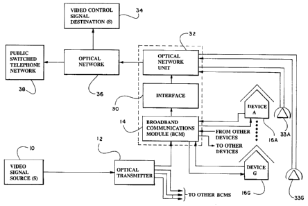
Fig. 3 is a block diagram including more detail of the
preferred environment of the preferred signal transport system as
illustrated in Fig. 2. In particular, the multiple transmission lines from
optical transmitter 12 to broadband communications module (BCM) 14
and to other BCMs indicate that the video signals may be provided to one
or more broadband communications modules. In addition, Fig. 3
illustrates that broadband communications module 14 transmits and
receives signals to and from one or more devices 16A - 16G.
The Optical Network in the Return Path
As discussed above in connection with the preferred return
path of the present invention, after the optical network unit 32 receives
the converted signals from the interface 30, the optical network unit 32
is operative to transmit the signals to one or more video signal
destinations 34. In the preferred environment, the optical network unit
32 may transmit the converted signals to an optical network 36. It will
be appreciated by those skilled in the art that the optical network unit 32
may be adapted as part of the optical network 36, rather than as a
separate unit. Preferably, the optical network 36 is a fiber-in-the-loop
(FITL) optical network, which can carry signals to provide conventional
telephone service, facsimile service, integrated services digital network
(ISDN), and other digital and data services including EtherNet
connections. From the optical network 36, the signals may be further
transmitted to one or more video signal destinations 34. For example,
signal destinations that may be connected to the optical network 36
include: video control networks, private data networks and signaling
3o networks. Also from the optical network 36, the signals may be further
transmitted to the public switched telephone network 38.
Advantageously, through the inclusion of an optical network in the
return path, a user may send signals from a device along a return path
that includes a broadband communications module, an optical network
unit, an optical network and to video signal destinations such as the
public switched telephone network.
CA 02251698 1998-10-14
WO 97/39583 PCT/US97/06216
Description of the Interface
In the general description of the preferred return path of the
present invention, it was explained that the broadband communications
module preferably receives modulated analog signals carrying digital
5 content from the device 16. The broadband communications module 14
then transits these signals to an interface 30 where the analog signals are
demodulated to digital signals and then transmitted to an optical network
unit 32. Additional details regarding the preferred broadband
communications module, the interface and the optical network unit are
10 now presented in connection with Fig. 4. Reference first is made to
Figs. 2 and 3 wherein interface 30 is illustrated as a functional block
separate from broadband communications module 14 and optical
network 32. In the preferred embodiment, no separate element
comparable to the interface block 30 exists. Rather, the functions of an
15 interface between the broadband communications module and the optical
network unit are preferably provided by certain functions carned out in
the broadband communications module, and to a lesser extent, in the
optical network unit, as is described below. Alternatively, as described
below in connection with Fig. 5A the functions of the interface may be
20 incorporated as part of or associated with the device or with the optical
network unit.
Fig. 4 illustrates certain components of the preferred
broadband communications module 14. In particular, it will be
appreciated that the broadband communications module 14 receives
modulated analog signals from the video signal source 10 at the optical
receiver 40. The analog signals are transmitted at a frequency between
SS - 860 MHz and may be transmitted at a frequency as high as 1
GigaHz. These signals are passed to a filter 42, which preferably is a
bandpass filter, and in particular, is a diplex filter. In a conventional
manner, the filter 42 passes the analog signals to a coaxial cable interface
44 for further transmission to the device 16.
With respect to the return path, the device 16 (or devices)
transmits analog signals to the coaxial cable interface 44. In an alternate
embodiment, the coaxial cable interface 44 may be provided with
multiplex signal inputs/outputs (RF combiner/splitter) such that if more
than one signal of the same type is received, then these signals may be
combined for processing. The coaxial cable interface 44 also may be
CA 02251698 1998-10-14
WO 97/39583 PCT/US97/06216
21
referred to as a "receiver" in the sense that it is a receiver of signals
from device 16.
From the coaxial cable interface 44, the signals (single or
multiplexed) are transmitted to the filter 42. Preferably, the analog
signals from the device 16 are sent at a frequency between 5 - 40 MHz,
and in the preferred embodiment, at a frequency of 15.45 - 17.756 MHz.
Upon receipt of the analog signals from the coaxial cable interface 44,
the filter 42 transmits the signals to a demodulator/converter 46. In the
preferred embodiment, the demodulator/converter is a QPSK
demodulator to EtherNet converter.
In the demodulator/converter 46, the signals are preferably
converted to digital signals, and in particular, are converted to digital
signals in an EtherNet format such as 10 Base T or 10 Base F. As those
skilled in the art will understand, the signals received from the device in
the demodulator/converter 46 are preferably combined with signals from
other devices for transmission to one or more signal destinations.
Signals from more than one device are passively combined in the
upstream connection through the diplex filter.
After conversion, the converted signals are preferably
passed to the optical network unit 32 in a manner well known to those
skilled in the art. In the preferred embodiment, the converted signals
are passed to one or more communications networks through one or
more communications network connection cards 48. The
communications network connection card of choice is an EtherNet card
preferably adapted for inclusion in the optical network unit 32. An
EtherNet card is a relatively inexpensive and popular communications
network connection card. Such an EtherNet card may be obtained from
Reltec, Franklin Park, Illinois. Those skilled in the art will recognize
that other communications network connection cards may be used as
well, or in substitution thereof. Advantageously, conversion of the
signals to digital format, and provision of the digital signals to a
communications network connection card 48 allow the signals to be
conveniently transmitted. to one or more signal destinations. For
example, from an EtherNet card, the signals may be transmitted in a
manner well known to those skilled in the art to an EtherNet router 50
(also referred to as a signal destination). Thus, the subscriber or user of
the device 16 is able to communicate through the preferred return path
CA 02251698 1998-10-14
WO 97/39583 PCT/US97/06216 _
22
with signal destinations such as the EtherNet router 50. It will be
appreciated that the provision of the digital signals to the EtherNet
router 50 (or other communications network connection) in the EtherNet
format (or other communications network format) allows the signals to
be directly interfaced with an EtherNet router (or other router) without
the need for additional elements or electronics. By avoiding the use of
additional elements or electronics, the present invention provides an
economical, convenient, reliable system for communications between a
device and a signal destination through the use of a connection between a
to broadband communications module and an optical network unit.
As noted, the converted signals from the
demodulator/converter 46 are preferably transmitted to a
communications network connection card 48 adapted for use in the
optical network unit 32. From the card 48, the signals may be routed to
one or more destinations. The routing of these signals is accomplished in
a conventional manner well known to those skilled in the art. The
signals may be routed in a conventional manner through an optical
receiver/transmitter 52 to an optical network 32. Typically, the signals
are transmitted in a conventional manner from the optical
receiver/transmitter at 1310 nanometers. In addition, from the card 48,
the signals may be multiplexed in a conventional manner with signals
from "POTS" cards 54 for further transmission to the public switched
telephone network 56.
Preferred Alarm and Control Features of the Present
Invention
Advantageously, the connection of the broadband
communications module and the optical network unit allows for the
implementation of certain testing, alarm and control features or system
with respect to the services offered to the subscriber or user associated
with device 16. With respect to the testing and alarm features, a radio
frequency (RF) output alarm and an optical signal alarm may be
implemented with the present invention. For example, referring to Fig.
4, one or more alarm features may be preferably implemented and
serviced through the connection of an alarm monitoring system 57 to the
public switched telephone network 56, and/or through certain elements
of the optical network unit 32, then to the broadband communications
CA 02251698 1998-10-14
WO 97/39583 PCT/C1S97/06216 _
23
module 14, and ultimately to the coaxial cable interface 44 servicing the
particular device 16 associated with a subscriber. A connection may be
made through the testing systems of the telephone network 56 to drop
test unit 58 to control process 60 and then to coaxial cable interface 44.
In this connection, signals are exchanged between the alarm monitoring
system and the control process 60 through the described path. These
signals may activate a program in the control process 60 in a manner
well known to the skilled in the art The control process 60 responds to
the receipt of the signals from the alarm monitoring system and takes
l0 action as provided by its programming. This action may involve
interaction with the signals passing through the coaxial cable interface
44, and/or interaction with the device 16. Alternatively, the action may
involve return of information to the alarm monitoring system. An
advantage of this feature of the present invention is that it eliminates the
need for any special status monitoring receivers or operation systems.
An example of an alarm feature is a feature that provides an
alarm with respect to the loss of RF signal or loss of optical input signal.
For example, if the video providers' RF signal is not recoverable at the
broadband communications module, then a sensor detects the loss of RF
signal and triggers a change in the state of the control unit (control
process). This change then is reported to the alarm monitoring system
57. As another example, the alarm monitoring system may be operated
to monitor a radio frequency output to trigger an alarm upon
degradation of the output delivered to the device or to trigger the alarm
upon degradation of an optical signal input to the broadband
communications module.
The preferred embodiment of the present invention also
includes control features applicable to the services provided to the
subscriber or user of the device 16. One example of a control feature
that is contemplated is the ability to turn-on or turn-off a subscriber's
CATV service. This control feature may be implemented in a similar
manner to the implementation of the alarm features as explained above.
Thus, if the CATV service provider has not been paid by a subscriber,
the service provider may send signals through the fiber in the loop
optical network unit to control process 60 so as to activate a program in
the control process 60 that results in service to the particular device
being cut off. The service is cut off at the interface 44. Once the
CA 02251698 1998-10-14
WO 97/39583 PCT/US97/06216 _
24
subscriber pays his/her CATV invoice, the service provider may (if it
has been paid enough) send signals through to control process 60 so as to
activate a program that results in service to the particular device being
turn-on. Advantageously, by the use of this exemplary control feature,
the CATV service provider does not have to send personnel to the
location of the device to turn on or to turn off the service. Thus, the
CATV service provider saves money and offers better service to its
subscribers.
An additional control feature that is contemplated is a
monitoring feature. With this monitoring feature, a service provider
may receive digitized signals representing monitoring data reporting the
health of the video signals being provided on the downstream path to one
or more devices. Conveniently, the service provider may receive these
digitized signals at a remote location. This monitoring feature is
preferably implemented in the same manner as the control features
described in the immediately preceding paragraph.
Another feature of the preferred embodiment of the present
invention is the drop test unit 58. As illustrated in Fig. 4, this drop test
unit 58 is adapted for use in the optical network unit 32 and generally
operates through a connection to the broadband communications module
14. This drop test unit 58 electrically tests the "drop" to the device. The
drop test unit accesses the control drop on an individual basis and
measures the electrical characteristics of the drop. In addition, the drop
test unit 58 may include programming features such that upon receipt of
activation signals from a service provider, the drop test unit 58, may be
able to interact with a coaxial cable interface 44 to a device 16 to check
for continuity. For example, a continuity check may include a check of
whether the coaxial cable is connected or connected properly to the set
top box. Thus, when a subscriber calls a CATV service provider to
complain about a malfunctioning television, the CATV service provider
can use the continuity check procedure to determine whether the
problem is associated with CATV service.
The testing processes provided by the present invention
allow a service provider to determine the nature of a problem plaguing a
subscriber. With the present invention, the service provider is able to
make a more specific determination of the nature of a problem than
prior art systems. As a result of the more specific determination, the
CA 02251698 1998-10-14
WO 97/39583 PCT/US97/06216
service provider may react more quickly to the specific problem and
solve it more quickly than with prior art systems. For example, as a
result of the testing features of the present invention, the service
provider is able to send the right service crew, if necessary, to the
5 device's location. In other words, the service provider is able to make a
more intelligent dispatch of a service crew. No longer will a technician
in a fancy uniform, penny loafers and a manicure be dispatched to a
problem that requires a technician in work coveralls, boots and a shovel.
Thus, the present invention allows the service provider to provide better
10 service and in a more efficient, cost saving manner.
Alternate Embodiments of the Signal Transport System of
the Present Invention
Figs. 5A and SB illustrate alternate embodiments of the
15 signal transport system of the present invention. In the embodiment
illustrated in Fig. 5A, a broadband communications module has not been
included as part of the return path of signals, and/or the downstream
path of signals. In this embodiment, the video signal source 61 delivers
signals to a device 62. The break in the transmission line between the
20 video signal source 61 and the device 62 indicates that other elements
may be present between these two elements, but are not shown in this
drawing. One or more of these elements may include a broadband
communications module. With respect to a return path, the device
directly provides digital signals to an interface 64, rather than providing
25 the analog signals to a broadband communications module as illustrated
in Figs. 2-4. As indicated by the dashed block 70, the interface may be
adapted for use in the device 62. Still referring to Fig. 5A, the interface
64 transmits the into digital signals in a communications network
connection format to a communications network connection card 66. As
indicated by the dashed block 72, the interface 64 and the
communications network connection card 66 may be adapted for use in
the device 62. Alternatively, the communications network connection
card 66 may be adapted for use in the device 62 with the interface 64
being a separate element or otherwise disposed for use in the present
invention. Preferably, the communications network connection card 66
is operative to transmit the digital signals in the communications network
connection format to the communications network connection 68.
CA 02251698 1998-10-14
WO 97/39583 PCT/US97/06216 _
26
In the embodiment illustrated in Fig. 5B, a video signal
source 80 delivers signals to a broadband communications module 82.
The break in the transmission line between video signal source 80 and
broadband communications module 82 indicates that other elements may
be present between these two elements, but are not shown in this
drawing. In this embodiment, broadband communications module 82
provides video signals received from video signal source 80 to a device
88. With respect to a return path, in contrast to embodiments described
in connection with Figs. 2-4, the device 88 provides analog signals
t0 (preferably modulated analog signals including digital content) to an
interface 86. The interface 86 preferably converts the analog signals
into digital signals in a communications network connection format and
transmits the signals in the communications network connection format
to a communications network connection card. 84. The card 84, in turn,
then provides the converted signals to a communications network
connection 90. As indicated by the dashed blocks 92 and 94, the
communications network connection card 84 and the interface 86 may be
included in different configurations of the present invention. For
example, as indicated by dashed block 92, the communications network
connection card 84 may be adapted for use with broadband
communications module 82. As indicated by dashed block 94, the
communications network connection card 84 and the interface 86 may be
adapted for use in connection with the broadband communications
module 82. Other configurations of the elements illustrated in Figs. SA
and SB wili occur to those skilled in the art.
In summary, the present invention allows for a connection
between CATV type services and communication services. In particular,
the present invention allows for a connection between, on the one hand,
CATV types services in the downstream path of video/data signal
transmission to a device and, on the other hand, communication type
services in the return path of the video/data signal transmission from the
device. With this connection, the range of broadband services that are
available to a subscriber is greatly expanded. In particular, the return
path of the video/data signal transmission may include optical networks,
such as fiber-in-the-loop networks, thereby providing the subscriber
with communication services of great bandwidth capacity.
CA 02251698 1998-10-14
~;_'~~~a yr_:'c1
27
Advantageously, the present invention provides an improved
return path that minimizes signal distortion of the signal transmission.
In this return path, the analog signals from a device are converted to
digital signals so as to allow for the transmission of signals to any wide
bandwidth communication network through any suitable communications
network connection card. In addition, the present invention provides a
system that is relatively inexpensive to set up, that functions well with a
minimum of equipment and minimum of modification to standard
elements, and that is easy to maintain and service.
t
r