Note: Descriptions are shown in the official language in which they were submitted.
CA 02251710 1999-02-08
MODUlAR BURIAL VAULT
Field of the Invention
The present invention relates to burial vaults, and more particularly to a
modular burial vault.
Background of the Invention
Burial vaults are structures placed into a gravesite to protect a decedent
confinement char,lber such as a casket coffin or um from natural destructive
~ler"ent:, such as water or the overlying weight of the earth. The vault prevents a
decedent confinemerlt ~,ar"ber from c~ sing when after natural decay the
decedenl confiner"ent c:l.an,ber has weakened and would otherwise be crushed by
the earth overlaying it.
Fr~f;~lbi icd~ed burial vaults are typically heavy duty metal structures
co,npri~i"g a flat base with a sul,~lantial metal dome. The dome is usually na--w:~r
than the base, resulting in a slight angle, br f~are, in the side walls of the dome
relative to the perpendicular from the base plate. This results in unused spaoe
within the burial vault when the decedent confi..en,ent chamber is placed inside.
I
CA 02251710 1999-02-08
Further, the weight distribution between the base and the dome is substantial. Adome typically weighs 300 Ibs., thus making it unmanageable to handle without
some lifting device being employed.
A further drawback to the pr~sent burial vaults is in fabrication and shipping.
The ba~se - dome configuration ne~ssi~ es at least two separate assemblies - onefor the base and one for the dome. Further, the present burial vaults are shipped
in an assen)bled fashion. This means that the dome and base are put together andshipped as a unit. The space enclosed by the vault is dead space in the shippingprocess.
In an alternative form, U.S. Patent No. 5,121,529, discloses a burial shell
formed by a cha,llber and a seal. The clla,.lber is formed as two sy""),e:t,ical half
shells. While alleviating some of the transportation problem, this does not alleviate
the problem of having two separdte assemblies for the top and the half shells.
U.S. Patent No. 4,249,289 discloses a co"lbi-ldlion burial vault and casket.
This design employs the same traditional base and dome configuration ~fiscussed
above. Therefore, this design has the same drawbacks.
United States Patent No. 4,314,390 di,dosçs a composite burial vault. The
design comprises a base liner which is placed into a grave. The liner is filled with
concrete. A top cover is then placed over the vault. Wllile the empty liner can be
t,anspo,ldd, the segi"e,lts are not modular and are not easily l.dnspo.ldble.
CA 02251710 1999-02-08
Brie~ Description of the Drawings.
FIG. 1 is an angled view of a modular enclosure segment in accordance with
the invention.
FIG. 2 demonsl,dlas a modular enclosure segment with another modular
5 enclosure segment rotated in place on top to form a burial vault.
FIG. 3 is a cut-away view of the bottom panel and anterior head panel as well
as boffom panel and posterior head panel forming an angle.
FIG. 4 is a cut-away view of the bottom panel w th attached left and right side
panels with defined angle.
FIG. 5 is an angled view of a modular enclosure segment without flanged lips
detailing the cGnne..tor panels bet ~Isen the left and right side panels and anterior
and posterior head panels.
FIG. 6 is a top view of a modular enclosure seg,nenl with flanged lips running
along anterior and posterior head panels, left and right side panels, and connector
1 5 panels.
FIG. 7 is a cut-away view of nested modular enclosure seymenl~
FIG. 8 is a bottom view of a modular enclosure seg,-ler( sh,~v,;ng rib supports
placed on the bottom surface of bottom panel.
FIG. 9 is a detailed cut-away view of a rib support with a support
20 pP.ss~g~v ~y.
CA 02251710 1999-02-08
FIG. 10 is a front view of a rib support showing a support passageway and
support strap running through.
FIG. 11 is a top view of a modular enclosure segment with flanged lips
showing the location of guiding mechanisms.
FIG. 12 is a cut-away side view of connected flanged lips showing the
workings of a depression and protrusion acting as guiding mechanisms.
FIG. 13 is a cut-away side view of connected flanged lips shol:;.,g a
guidance device as a hole in one flanged lip with a bolt.
FIG. 14 is a cut-away front view of a normal burial vault.
FIG. 15 is a cut-away front view of a burial vault of the p,~:sent invenffon anddemona~dti, ,9 the distance and volume savings.
Summary of the Invenffon
An object of the invention is to provide a modular burial vault where no
excess asse" Ibly would be utilked in its production. Another object of the invenUon
is to provide a burial vault that minimizes bans~vo-ldtiGn space and thus costs
asso~.;ated with transpo, l-dtion of the vaults. A further object of the invenffon is to
provide a design for a burial vault that cuts down on the thickness of the left and
right side walls, and thus reduces manufactufing costs. A further object of the
invention is to provide for a burial vault whidh weighs less than the burial vaults of
the prior art. This allow-s a minimum of pe.~onnel to be used during the handling of
CA 022~1710 1999-02-08
the ?arts, and during the final assembly. A further object of the invention is to
minimize the need for external lifting devices during all phases of modular
construction, transportation, handling, and final burial vault placement. A further
object of the invention is to minimize the excess volume in a burial vault, allowing
for closer spacing of plots within a given burial area.
The present invention therefore provides an inexpensive and efficient burial
vault. The invention comprises two modular enclosure segments, or box-like
structures, which, when joined together, from an enclosed space in which a
decedent confinement chamber may be placed
1û In a preferred embodiment, the invention is directed to a box-like structure
constructed from light weight steel. The box like structure has a bottom panel,
anterior and po~-terior head panels, and a left and right side panel. The head panels
and side panels are connected to the bottom panel with a slight flare outward, or
inscribed angle between the bottom panel and the connected panels a little more
than perpendicular.
In the preferred embodiment, the slight flare produces a gap between the
head panels and the neighboring side panels. This gap is filled with an
appr~,pi iat~ly sized and shaped side extension connector panel, thus producing an
open and continuous box like structure anchored by the bottom panel.
The side panels, head panels, and connector panels that fill the spaoe
between them forrn a penn-~,ter to which a flanged lip is connected. In a pn,f~ d
CA 02251710 1999-02-08
embodiment the flanged lip is adapted with at ieast one socket-like indentation and
one protrusion. Thus when one modular enclosure segment is rotated so that the
interiors or concave faces of the box structures are facing one another an
indentation will line up with a protnusion so as to inhibit further movement. This will
5 also indicate a proper lineup of the flanged lips. The lining up of the lips properly
will significantly increase the strength of the overall structure.
In the pr~ f~ r,~d embodi",ent rib supports are added to the bottom panel on
both the interior or concave face of the box structure and the exterior, or convex
face of box structure. These supports are adapted to receive a hook or strap, so
10 that the modular box can be l~ted using some extt:",al lifting device.
The entire stmcture can be made of a metal pre~erably a lightweight metal,
a plastic ",ate:rial including ther",opl~ s and injection molded plastics foam as
well as fiberglass.
Detailed Descri~ tion of the Invention
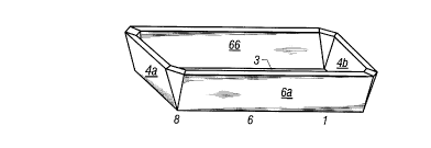
FIG. 1 de"lonat-ates a modularenclosure seylllenl 1 for use in the invenUon.
The modular enclosure seg",ent~ are placed togeU,er as shown in FIG. 2 concave
faces facing each other to form burial vauit 2 to which may be placed a dec~dent
confinement cha"~ber, such as a coffin or casket. Each enclosure segment 1a is
substantially identical to any other enclosure sey,nent 1b. In the most pr~,h.,~d
20 embodiment each enclosure se~",ent 1a is identical to any other enclosure
CA 02251710 1999-02-08
segment 1b By having enclosure segment of the burial vault identical to the
opposite piece, a manufacturer need only produce the one modular segment, thus
saving greatly in manufacturing costs.
Tuming in greater detail to the modular enclosure segments, each modular
enclosure segment is co,~,prised of a bottom panel 3. Anterior head panel 4a andposterior head panel 4b are connected to bottom panel 3, and the inscribed angle5 between bottom panel 3 and each of the head panels 4 is slightly greater than
ninety deg, ~es, producing a slight flare to modular enclosure segment 1, as shown
in FIG 3. Two side panels 6 - left side panel 6a and right side panel 6b - are
1 û connected to bottom panel 3 in a similar fashion to fomm inscribed angle 7 in FIG.
4. If side panels 6 and head panels 4 are connected to bottom panel 3 in a slightly
flared fashion, a roughly triangular area between head panels 4 and side panels 6
is left empty.
In a preferred embodiment, the side panels would be ridged, or rippled. This
~ridging" or ~rippling" of the longer side panels would create inherent beams in the
side panels, thus mi~ king any bowing of the modular enclosure seylnent. In
anotherembodi-"enle"lphaski"gsupport,thesidepanelswouldhavesupponribs.
These support ribs could either be attached or could be a part of the mold for the
enclosure.
In a p~f~:lled embodiment,as set forth in FIG. S~ a side ext~nsion panel 8 is
conne~,t~ to each head panel 4 - side panel 6 i,~,t~rae~tion, thus filling the naturally
CA 02251710 1999-02-08
occurnng empty area produced by the slight flaring of side panels 6 and head
panels 4. The addition of side extension panel 8 to complete the full wall is
preferable because of the added strength and stability of the final vault.
A flanged lip 9 is attached to the perimeter defined by side panels 6 and
5 head panels 4. If side ext~:nsion panels 8 are present the flanged lip would also be
attached to them. thus forming a lip perimeter cornplctely around modular enclosur
segment 1 as shown in FIG. 6.
In the pre~ d embodi",enl the modular enclosure segment 1 would be
made of 14 gauge steel. Other burial vaults require the use of heavier duty steel
10 but due to the design chard~le,i:,lic~ of the present invention a lighter ,.,a~,ial can
be e" ,~ 'n~d. The lighter duty ., Id~:l ial is cheaper to use in the production p, ~ess
easier to form and lighter to ship. These all contribute to the overall cost
effectiveness and emciency of the invention. Other grades of steel could be used.
Plastics especially the use of injection molding and the""opl~li~ could also be
15 utilized in the invention. In,e~ foams or fiberglass could also be employed in the
manufacture of the invention.
The design of the modular enclosure segment 1 also contributes greatly to
shipping costs. The slightly flared design of the head panels 4 and side panels 6
allows muKiple modular enclosure segment 1 to be completely nested within one
20 another. Thus the units could be shi,Jped as stacks of modular enclosure
segr"enb with little wasted space. When nested as shown in FIG. 7 it should be
CA 02251710 1999-02-08
noted that multiple modular enclosure segment 1 and 1 a take just over the volume
of modular enclosure segment 1. Thus great efficiencies in shipping are achieved
by using nested stacks of the present invention.
In a preferred embodi,nent, as shown in FIG. 8, support ribs 10 are attached
5 width-wise, or parallel to head panel 6, to bottom panel 3. It should be noted that the
support ribs 10 can be placed lengthwise on bottom panel 3 as well. Support ribs
10 can be attached either on the face of bottom panel 3 fonming the convex face,
or the exterior face, of modular enclosure segment 1, or on the face of bottom panel
3 forrning the concave face, or the interior face, of modular endosure seylllent 1.
In the preferred embodiment in which the ribs are placed solely on one face of the
bottom panel, the ribs are placed on the interior face of bottom panel 3.
For ease of manufacturing, shipping, and use, ribs are plaoed on both faoes.
This ensures that any modular enclosure seg,nent is identicaî to any other one.
Support ribs 10 give added support to counter weight placed on the exterior faoe of
15 the modular enclosure segment 1. In addition, ribs placed on the interior faoe of
bottom panel 3 ensure that a space is present between the modular endosure
seyment~ when nested. When nested, the e~tterior face of bottom panel 3 of the
t~,p" ,ost modular enciosure segment wouid rest upon the support ribs placed on the
extt:rior face of bottom panel 3 on the bottom modular enclosure seS~,nent. This
20 causes the topinos~ modular enclosure sey",enl's flanged lips to rise a set amount
CA 02251710 1999-02-08
ovar the other segment's flanged lips. This aids in handling and separation of the
nested segments after delivery.
In a pre~erred embodiment, support ribs 10 are designed with at least one
passage 11 through them. As shown in Figs. 9 and 10, this allows the support rib10 to be used with straps, hooks or other lifting devices for handling purposes.Preferably, at least two passages 11 would be present. Pass~ges should be
sy" ", l~t- ical with respect to support rib 1 û, so that if straps are placed through thern,
equal loads will be placed on each strap.
An additional advantage of the modular enclosure segment is now realked
in their actual use. The ability to use lighter materials greatly aids in the handling
characteri~lics of the burial vault. Heaviem"a~ri~ls greatly increase the weight of
the unit. Thus, it is easier for handling at grave side and shipping when using the
lighter materials. Secondly, other conventional buAal vaults can have a lopsidedproportion of weight in one segment or another. Thus, a 90 - 10 ratio on an
average 300 pound unit would mean that one segment would be 270 pounds. Wth
this weight, some sort of .nechanical lifting device would be required to move the
heavier segment. In the current design, the modular enclosure seg",e"t~
co",p,ising the burial vault are identical. Wth the lighter materials used, two men
can easily lift, handle, and place the unit without the aid of an extemal li~ting device.
To forrn the final burial vault 2, one modular enclosure seyl nent 1 is lowered
into the dug grave concave face facing upwards. This can be accomplished
CA 02251710 1999-02-08
manually or by the use of straps run through opening 11 in support ribs 10. Another
modular enclosure segment 1 concave face facing downwards is then lowered
onto the first modular enclosure segment. As before the modular enclosure
segment may be lowered manually or by using straps hooks or other lifting
mechanism placed through opening 11 in support ribs 10. The top modular
enclosure sey,-,ent is then adjusted so that flanged lips 9 of both modular enclosure
sey, ~,er,t are engaged in a touching ~Id~ionship about the peri"~eter of the modular
enclosure segmenrs.
In a prererred embodiment, flanged lips 9 have guiding devices 12 and 13
10 to line up the flanged lips properly. In one embodiment. this guiding devioe
cG, np, i~es alte, . ,ating deprt:ssions and protn~sions as shown in Fig 11. Thus when
the accGn ,panying modular enclosure segment is rotated and placed concave face
down on the concave face up modular enclosure seyn,er,l ~ere will be a matching
protrusion 13 - depression 12 pair facing one another. This is shown in two
alternatives prssent~d in FIGS. 12 and 13. In FIG~ 12 flanged lips 9 and 9a have
been tumed so protrusion 12a "Idtches co"esponding depression 13. This serves
to match up the modular enclosure segment.
In FIG. 13 the invention uses a guide hole 12b and cG,lt:sponding bolt 14
to match up n;anged lips 9 and 9a and stabilizing the overall burial vault.
CA 02251710 1999-02-08
The use of flanged lips allows greater stability for the unit, and provides extra
support in the segment. This extra support of the design allows for the use of lighter
materials in the construction of the invention.
Another added benefit of the overall design is realized in the symmetrical
5 aspects of the burial vault construction. In a normal burial vault, flanged sides of the
head cause the unit to have an overall profile as shown in FIG. 14. The sy" "~e~ ic~l
design of the present burial vault 2 with the same angle of nanged side is further
r~3p,~sented in FIG. 14. Thus, for the same width casket or coffin, the sy"",~et~
design of the present invention allows for a plot width less than that of a
10 convenffonal burial vault, as shown in the supe" ositiGn of FIG. 14. This leads to a
greater economy in the size of plots in a particular area.
Various modiricdtions may be made in the nature, composition, opelation
and a"dngei"ent of the various elements, steps and procedures described herein
without departing from the spirit and scope of the invention as defined in the
following claims.