Note: Descriptions are shown in the official language in which they were submitted.
L~ L~ J_ ' i ~ ' CA 02251809 1998-10-13
MET~HOD, A~PARi~TUS f'.N~ KITS ~OF~ SEQ~JENCING OF
~JCLEI~ AC~:)S USING MULTIPLE l:)YES
.
DESCR~TIOI'~
BACKGROUND OF THE IN~ENl'ION
Thi~ application relates to an improved me~hod for se~uencing of nuc~eic acid~ using
mt~ltiple fluoresce~lt l~bels, and to ~rpa-~tu~ and kits adapted for use witl~ the metho~
Sequencing of nucleic acids usin~ the ~13in terrnination method in~olves the general
steps of combinin~ th~ target nncleic acid polymer to be sequenced with a sequenci g pnmer
S which hybridizes with the tar~et nucleic acid polymer; e~tendir,~ the sequer.ci~g ~ r in ~he
presencc of nor~nal nucleotide (A, C, G, ~d 'r) and a chain-termina~g nucleotide, such a~ a
dideoxynucleotide, which pr~ents further extension of the pnm~ o~çe ircorporated; and
analyzing the pr~duct for the le~gth of the ~xtended ~ra~ncnts obtained. Analysis of
fra8ments may be done by electrophoresis, for example on a polyacrylamide ~el.
Alth~ugh this type of analy~is was ori~n~Lly ~ Çv.IL~çd us~ng r~diolabeled fr~ t~
which were dc~ectcd by autoradio~raphy af~er separation. modcrn automated D~ sequencers
generally are desi~ned for llse wi~h sequencing fr~gmente having a fluore~c~ll label. The
fluorescently labeled fragments are detected in re~l time ~lS they m~grate past a de~ector.
US Patent No. 5,17 L ,534 ~hich is incorpora~ed herein by reference descnbes a
Yariation of Ihis basic ~e~u~ncin~ in which f'our dil~ferent fluoLcsce~t labels arc
enlployodl one for each sequencing reaction. The fr~ nt~ dcvelop~d iII the A, G, C and T
se~uenci~g re~ctions are lhen recombincd a~d intr~duced together ~nto a s~p~tion matrix. A
sy~tem of optical filters is used to indi~idually detect the fluorophores as they p~ss the
detectt-r. This allows the t~roughput of a se~u~ncing apparatus to be incre~sed by a factor of
20 four, sincc the four sequencin~ reacti~n which were previously mn in four separate laneg or
capillaries ca~ now be nln in c~e.
Olesen ct al., "Chemiluminescent DNA Sequcncing with M~l~sp~ex Labe~ing",
Bio~eckniques I5 480-485 (1~9~) describe a mo~lifir~tior of a S~n~er sequencing techmquc
in which several samples (e.g. ~our samples) arc sepa.~tcly used as templates for the
2S production of sequencing fragrncnts. Each sample was reac~ed with a different primer species
labeled w~th a ~irf~le~l~ cherr~~ n~scent hapten. Tlle A reactions from each sample were
A~lENDED C5~c~T
L~ ) ' . L <~ CAl ' o i 2 ~ 18 0 9 19 9 8 r ~ )' )'J I ~ ; jr ~
then c~ bi~ed, 3nd lilcewise the C re~ctions, the G reactions a~d the T r~ o~s. The
comb~ned r~ were t~e~ separated by e~ccucl horesis, ~r.sfe~e~ a~er sep~tinn tO a
~ylon membrane and sequen~ially observed using the differe~t cherni~llminescent labels. I~e
signal strength for each detection d~creases with e~ch successive label ~nte~o~ated
It is an objec~ of the present 1nvention to provide a fi~er improveme~t for use w~th
chain terrnin~ion sequencing ,.,r~ti~n~ which c~ increase the ttlroughput of an ~s~lu,.l~L~l.
A~,~,E~ LLT
- -
CA 02251809 1998-lo' i3 ~I L .~
SUM~IARY OF 7HE ~ TION
~n order to use nuclçic ~cid se~uencing as a dia~n~stic lool, it will ~e necess~ry to
detumine the sequence ~f the s~me DNA re~ion from many samples. ~he present inven$lon
rnake~ it possible to increase the throu~hput of an instrument being used for this purpose.
Thus~ a first ~specl of the invenlion prov,des a method for evaluating the s~quence of a ~r~es
nucleic ~cid polymef in a plurality of samples. In this meth~d, each ~mple is f~rst di~,ided into
four aliquots which are con~bined w~t~ four se~encin~ .eaction mL~ res. E2ch sequencing
rcaction m~xnlre contaiIls a pol~n~erase en2~e, ~ Fnmcr for hybrid!~ing urith the t3rg~t
~ucleic acid, n~cleotide feedstoc~s and a different dide~xynucleotide. This results in the
10 form~t~nn o~an A-n~ Lu~, a G-mixture, a T-mixnlre and 3 C-mixture for each sample
cc~aiRir.g ~ro~uct oligon~ ou~ i~a~ments of varying lengths. The product oligonucleotide
fr~ n~s a,re labeIed vvith spectro~copically-delectable Lag, for example a fluore~ce~t ta~, and
thesc tags will gencrally be the ~am~ for all four scquencing r~cti~7ns for ~ sample. However~
the spectroscopically-~etec~lble ~ags used for each s~mple 3re distin~uishable one ~om the
15 other on the ~asis of th~r absorption, excitalion or emi~sion ~pec~a.
Next, the .~-m~xtur~s for e~ch sample are combincd to form ~ combincd A mixrure, the
G-mixtures are combln~ to fonn ~ combincd G-~ixhlre ~nd so on for all four miYrures. The
c~mbilled mixturcs are loaded onto a separati~n ma~ix at s~aratc loading sites and an electric
field is applied to cause lhe product oli~o~ oti~e fiagments to migr2le wit}lin Ihe separation
20 matnx. The sepa~ed product oLigonucleotide fragments haYi~ ifr~ t
sp~,koscopica3 y~esectablc tags are ~ct~cted as they ~rate within thc separation mal;r~x.
- 'rhc mcthod of the invention c~ be used as describc~ above to determine Ihe positio~
of evcry ~ in the sec ~ c~, ar it call be uscd t~ deterrnine the pGSitiOIl of less than ~1~ four
~ascs. For example, thc method can be used to detcm~in~ thc pasition of only the A b~ses
2~ wi~i~ a s~q-lR~l~e for some diagnostic applications.
A fi~her aspec~ of the prese~t inventio~ is a kit usefill for diag~lostic $~1l~r~rin~ of a
selected portion of a gcne. One ~mbo~imellt o~ such ~ kit conta~ns a plurality of s~lu~ncing
primer~ f~r the sPl~ct~d portion of thc genc. each s~uencin~ prirner bcing identicaL in its ~IA
sequence but being labeled wi~ a cli~.~ spectroscopically-detectable ta~.
A f~rther aspcct of the invention is an appa~atus for perf~rrni~g the metho~ of the
in~eneion~ Such ~n apparan~s compnses
t~ CO S~
CA 022~1809 1998-10-13
WO 97/40184 PCT/CA97/002Sl
(a) means for providing excitation energy to a detection site within a separation
matrix disposed within the apparatus;
(b) means for detecting light emitted from fluorescently-labeled oligonucleotidefragments located within the detection site;
(c) configuration control means, operatively connected to the means for providing
excitation energy and the means for detecting to provide combinations of excitation
wavelength and detection wavelength specific for a plurality of di~l ~nl fluorescell~ly-labeled
oligonucleotide fragments; and
(d) data processing means, operatively connected to the configuration control
means and the means for detecting for receiving a signal from the means for detecting and
~signing that signal to a data stream based upon the combination of excitation wavelength
and detection wavelength set by the configuration control means.
BRTFF DF.~CR~PTION OF THE DR~WINGS
Figs. 1 A and B shows a schematic representation of the method of the invention;Figs. 2 A, B, C, and D show excitation and emission spectra for theoretical sets of
useful fluorescent tags; and
Fig. 3 shows an apparatus for evaluating the sequence of nucleic acid polymers using
the method of the invention.
DETA~T F.n DF.SCRTPTION OF THE INVENTION
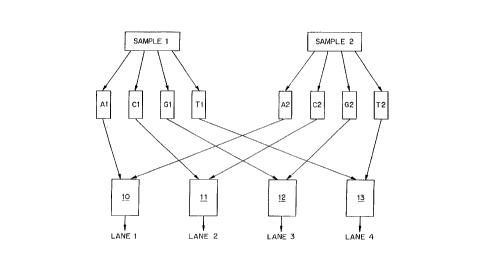
Fig. l A shows a schematic representation of one embodiment of the method of theinvention. The figure depicts the application of the method to two samples for clarity. As will
be appal-enl from the discussion below, however, the method of the invention is not limited to
two samples, and is in fact preferably applied for four or more samples, up to a limit imposed
only by the number of di.ctingllish~ble tags which can be identified.
As shown in Fig. IA, two samples, "sample l " and "sample 2" are each divided into
four aliquots and these aliquots are introduced into sequencing reactions Al, Cl, Gl, and T1,
and A2, C2, G2 and T2. Each sequencing reaction contains the reagents necessary for
producing product oligonucleotide fr~gmPnts of varying lengths indicative ofthe position of
one-base within the target nucleic acid sequence. These reagents include a polymerase
,
. . .
I L . '~ L _ J ' CA 0 2 2 5 1 8 0 9 1 9 9 8 - 1 0 - 1 3
. ~
enzyme, for ex3tnple T7 polymesa~e, Seque-l~seTU, Thermo SequenaseT~, or the Klenow
fr~ nt of DNA polyln~l~se, A, C, G ~ T nucleotide feedstocks; one typc of ~hain
tcrminaîing dideoxynuclcotid~; and a s~quenc~ng primer.
A~er Ihe product aligonl~cleotide fragments are formed in each reaction mlxture, the
prodlucts from reaction mixturc A I are combined with ~h~ products frorn reacti~n mixture A2
to form a c~mbined mixlure 10 which is loaded onto lane 1 of ~ sep3~tion matrix. Likewise,
the products from reaction mixturc C1 are c~mbined with the prodlIcts from rea~;tion mixturc
C2 to forrn a comhine~ mixLure I 1 which ~s loaded onto lan~ ~ ~f the separation matrix: the
products from reactioll ~ixnlre Gl are combined with the prad~cts from re~ction mixture G2
10 to forrn ~ combined mixture I2 which is !oaded onto lanc 3 of the s~paration matI~x; and the
products from reaction mi-.ctur~ T1 are combin~ ~ ~lie ~r~e;~ m reac..o.. i.~ re r
to fonn a combi~ed mLltt~re 13 whic~l is ioaded onto lane 4 of tbe scpara~i~n rna~ix.
The key to the pre~ent in~entin~ thc use of l~bels i3~ the reactia~s A 1, ~ l, G l, ~nd
Tl which are ~ tn~ ab~e from the labels used in reac~iuns A2, C~, G2 and T~, respec-
tively. Thus, u~like the method ~escnbed in US Pa~er~ ~lo. S,171,534 where the labels us~d
for lhe A, C, G. and T r~ction~ for a sample are distinct~ in the present inveneion ~he labels
used f~r the follr sequenci~.~ re~ctions for any one samplc can be, and prefierabi~ are, the
same. Tn~tearl, it is the labels whlch are used in the seueral samples which are distinct in the
method ~f the insres~tion~
A~ ~ltem~tive ~mbodimeDt ofthe inventlon is illustrated in Fig. IB. I~ this case~ the
~p~ r wa~ts to sequence a plurality of genes (or di~ferent exorls of the same gene~ from one
patient sample, The s~nple ~0 is divided into faur aliquots. A sequç.~ ng re3ction mix
co.~t~ining the reagents n~ceCc~ for prodncing p~duct oli~m~c1eo~lde ~ nents of ~ng
leng~hs is'ad~ed ~o each ~liquol. 1 he sequencing n~ix added to a first aliquot contains all
the re~ for an A tesmination rcaction, plus ~ plorality of sequ~ g pri~ners, each onc
labcled with a rliet;ng~ h~7~1e llu~yhore, ~nd eaeh one being specific for a ~ rt~ gene (or
dif~.c.~t xon of thc same gene). ThC scquencing mix added to d se~ond aliquot con~in~ all
of the reagents for a C termi~ation reacticn, plus thc same plu~lity o~'se~ nc;n~ pnmers.
Sequ~ r~act~o~ mixes for (i a~d ~ are made in the same fashion. These sequencingmixtur~ are rea~ted to produce oli~ntlllcleotides frag~slen~;, ~d the., loaded onto lanes 21, 22,
23, and ~4 of a sequ~ ng gel and s~pAr~t~d Us~ng t~s technique, any number of genes or
CA 022~1809 1998-10-13
W O97/40184 PCT/CA97/002Sl
exons in a sample can be ~imlllt~neously sequenced up to the limit imposed by the number
tin~lish~ble tags which can be identified.
Suitable labels for use in the present invention are fluorescent tags. These can be
incorporated into the product oligonucleotide fragments in any way, including the use of
5 fluorescently-tagged primers or fluorescently-tagged chain terminating reagents. Colored dyes
detected using absorption spectroscopy can also be employed.
The fluorescent tags selected for use in the present invention must be dictin~ h~hle
one from another based on their excitation and/or emission spectra. For example, as shown in
Fig. 2A, a set oftags could be selected which had overlapping emission spectra (Eml, Em2,
Em3 and Em4) but separate and ~listinglli.~h~ble excitation spectra (Exl, Ex2, Ex3, and Ex4).
A set of tags could also be selected which had overlapping excitation spectra but separate and
distinguishable emission spectra as shown in Fig. 2B. Further, as shown in Fig 2C, a set of
tags could be selected in which some of the tags have overlapping excitation spectra (Exl and
Ex2) but separate and ~listingllish~hle emission spectra (Em] is ~ tinglli~h~ble from Em2),
15 while the others have separate and distinguish~ble excitation spectra (Ex1, Ex3, and Ex4) but
overlapping emission spectra (Em 1, Em3 and Em4). A further combination of excitation and
emission spectra is shown in Fig. 2D.
Examples of sets of suitable tags, together with the wavelength maximum for the
excitation and emission spectra are shown in Table 1. Many other fluorophores are available
20 that can be used as labels for DNA sequencing reaction products. Such dyes are available
from Applied Biosystems, Inc. (Foster City, CA), Molecular Probes~ Inc. (Oregon) and others.
CA 022~1809 1998-10-13
WO 97/40184 PCT/CA97/00251
Table 1: Fluorescent Dye's suitable for use with the invention
Fluorescent Dye Excitation Max (nm) Emission Max (nm)
Texas Red X 599 617
Carboxy-X-Rhodamine 585 612
CarboxyFluorescein 494 521
CarboxyTetraMethylRhodamine 561 591
Carboxycyanine 5.0 650 667
Fig. 3 shows a basic layout for an appa- dllls for ev~ ting the sequence of nucleic acid
polymers using the method of the invention. Light from a light source 31, which may be for
example a laser, a light emitting diode, a laser diode, an incandescent or polychl o,..alic lamp,
or any combination of such sources, is passed through an optical filter 32 if necessary to select
5 an approp.iate excitation wavelength which is directed to a detection site 33 in a separation
matrix 34. Additional optical components, not shown, may be included as necessary to direct
light to the separation matrix. Light emitted by fluorescent tags in the detection site 33 passes
through a second optical filter 35 to a detector 36. Again, additional optical components can
be included to direct light from the separation matrix 34 to the detector 36. Either or both of
10 the optical filters 32 and 36 may be adjustable under the control of a microprocessor,
minicomputer or personal computer 37 to provide various configurations of excitation and
emission wave]engths as di~cussed more fully below. The output from the detector is then
transmitted to a data processing system such as a dedicated microprocessor, minicomputer or
personal computer 37 for anaiysis to produce a report on the sequence ofthe sample being
15 evaluated.
In the case where the properties of the selected tags are of the type shown in Fig. 2A,
the optical filter 32 may adjustable, for example by rotating several di~e. c~L filters through the
path of the excitation beam, to produce excitation beams corresponding to the different
CA 022~1809 1998-10-13
W O 97/40184 PCT/CA97/00251
excitation wavelengths of the tags. An acousto-optic tunable filter of the type employed in
U.S. Patent No. 5,556,790, which.is incorporated herein by reference, can also be used to
- separate excitation wavelengths. Optical filter 35 may then be simply a cut-off filter selected
to exclude light of the excitation wavelengths from the detector. Information concerning the
position of the optical filter 32 as a function of time is tr~n~mitted to the data processing
system, and used to permit intel yrelation of the fluorescence data. Thus, when the optical
filter 32 is in a position that corresponds to the excitation spectrum of the tag used to label
sample 1, the data processing system interprets the emission intensity as data for the sequence
of sample 1, when the optical filter 32 is in a position that corresponds to the excitation
spectrum of the tag used to label sample 2, the data processing system inle, ~ ts the emission
intensity as data for the sequence of sample 2 and so on for as many di~el e-~L tags are used.
In the case where the properties of the selected tags are of the type shown in Fig. 2B,
the optical filter 35 is adjustable, for example by rotating several dirrerenl flters through the
path of the excitation beam, to selectively collect emissions wavelengths corresponding to the
dirrel ~,l tags. Optical filter 32 may be simply a cut-off or band-pass filter selected to exclude
light of the emission wavelengths from the detector. Information concerning the position of
the optical filter 35 as a function oftime is l~ Lled to the data processing system, and used
to permit inte,~,el~Lion ofthe fluorescence data. Thus, when the optical filter 35 is in a
position that corresponds to the emission spectrum of the tag used to label sample I, the data
processing system interprets the emission intensity as data for the sequence of sample 1, when
the optical filter 35 is in a position that corresponds to the emission spectrum of the tag used
to label sample 2, the data processing system interprets the emission intensity as data for the
sequence of sample 2 and so on for as many dirrel ~nl tags as are used.
Finally, in the case where the properties of the selected tags are of the type shown in
Fig. 2C, both optical filter 32 and optical 35 are adjustable in synchro~liG~lion to control the
excitation and emission wavelengths being monitored. Information concerning the position of
the optical filters 32 and 35 as a function oftime is transmitted to the data processing system,
and used to permit interpretation ofthe fluorescence data. Thus, when optical filter 32 is in a
position that corresponds to excitation spectrum Exl in Fig 2C, and optical filter 35 is in a
position that l,anslllils the light of the wavelength of emission spectrum Eml, the data
processing system interprets the emission intensity as data for the sequence of the sample
. . .
CA 022S1809 1998-10-13
WO 97/40184 PCTICA97/00251
labeled with tag 1. When the optica} filter 35 is in a position to l~ slll;l light ofthe
wavelength of emission spectrum Em2, on the other hand, the data processing system
interprets the emission intensity as data for the sequence of the of sample labeled with tag 2.
When absorption of light rather than emission of light is monitoredl the apparatus still
5 has subst~ntially the structures shown in Fig. 3. In this case, however, any optical filters
employed before and after the separation matrix are selected to pass light of the same
wavelength, corresponding to an absorption of the selected spectroscopically-detectable label.
The light source 31 in the appal ~tus of the invention may be a single light source which
is moved across the gel to irradiate each detection zone individually, for example as described
in US Patent No. 5,207,880 which is incorporated herein by reference. The light source 31
may also be a singe light source which is split into multiple beamlets, for example using optical
fibers or through the use of a beam splitter such as a spot array generation grating to each of
the detection sites as described generally in US Patent Application Serial No. 0~/353,932 and
PCT Patent Application No. PCT/US95/15951 which are incorporated herein by reference.
The light source 31 may also be multiple individual light sources, each of which irradiates a
subset of one or more of the detection sites within the separation matrix.
While optical filter 32 described above can be used effectively to provide selection of
excitation wavelength, it will be understood that other approaches to providing di~relenl
excitation wavelengths can be used as well. For example a plurality of lasers of different
wavelengths could be used, with the light from each directed in turn to the detection site. For
detection of product oligonucleotide fragments in multiple lanes of an electrophoresis gel, one
set of lasers might be used (one for each necessary wavelength) ~,vith light from each of the
lasers being conducted by optical fibers or through the use of a beam splitter such as a spot
array generation grating to each of the detection sites as described generally in US Patent
Application Serial No. 08/353,932 and PCT Patent Application No. PCT/US95/ 15951.
Optical switches, operatively connected to the data processing system, are used to select
which of the excitation wavelengths is striking the detection zone at any given time, in the
same manner as a rotating optical filter could do. A detector assembly which scans across the
lanes of an electrophoresis gel could also be used, for example as described in US Patents
Nos. 5,360,523 and 5,100,529, which are incorporated herein by reference, although the time
.
CA 022~1809 1998-10-13
WO 97/40184 PCT/CA97/002Sl
required for such a device to scan all the lanes of a gel may be a limiting factor in applications
with short total migration times.
It will also be appreciated that multiple optical filters mounted on individual detectors
could be used in place ofthe adjustable optical filter 35 and the single detector 36 shown in
5 Fig. 3. Similarly several detectors with adjustable optical filters might also be used.
Other optical components which separate light by wavelength may also be used in
place of optical filter 3 5 . Thus, for example, a diffiaction grating or prism which spatially
separates light of differing wavelength may be employed. In this case, radiation from the
dirre~ t;"l fluorophores will be distributed in space, and can be detected by dedicated detectors
10 such as photodiodes, CCD elements (linear or X-Y). Similarly, distinct optical filters for each
wavelength can be employed in combination with a multiplicity of detectors. Optical filters
which are transmissive at the emission wavelength of one fluorophore and reflective at the
emission wavelength of a second fluorophore can also be used to direct emitted light to
separate detectors depending on wavelength.
The detectors used in the apparatus of the invention may be photomultipliers,
photodiodes or a CCD. As noted above, the apparatus can be configured with one or more
detectors for each detection site. The apparatus can also be configured such that one detector
overlaps with several detection sites if the excitation light is directed to the detection sites one
at a time. In addition, the apparatus can use a single detector (or a small array of detectors)
20 which is sc~nned across the gel during detection.
For determining the sequence of a selected region of DNA using the method of theinvention, a kit may be form~ ted. Such a kit comprises, in packaged combination, a
plurality of containers, each cont~ining a reagent for the sequencing of the selected region of
DNA. The reagent in each container has a reactive portion, which is involved in the
25 sequencing reaction, and a fluorescent label portion. The label portions of the reagents in
each container are dilrel e"l and (li~tingnich~ble one from the other on the basis of the
excitation or emission spectra thereof.
In a pr~re, I ed embodiment, a kit in accordance with the invention comprises a plurality
of primers for sequencing the selected region, each of the primers having a di~l enl and
30 rli.ctinvllich~hle fluorescent label. Thus, the reactive portions ofthe reagents in this case are
the oligonucleotide primer to which the labels are ~tt~ched. The reactive portions may be
.J ~ + 1'~ J~ i
I I L . . ~ ' J - ._ l d - l L - ' - - CA 02251809 1998-10-13 -
- 10-
dif~ercnt f~om olle ~other, but are preferably the same~ Such a kit may also include additional
reag~Dts for seql~cin~ including polymer~se enzymes, dideoxynucleotides and buffers.
Alternati~ely, the kit may contain one primer f~r the selected regicn ~nd a plurality of
containers of chain-termin~ting nucleotides, each labeled wllh a different and distinguich~ble
S fluarescent label. In this case, the reactive portion of the re~gent is ~he chain t~-min~in~
nuclcotide which can be illCOlt)ur~t~ in place of a no~al nucl~otide during thc sequencir~g
reaction. The Icit may include reagent~ havin~ just one type of c~ain-t~rminatin~ nucleotido,
for example ddA with a plurality ~f distinct flll~rescent labc]s, o~ it may include reag~nts
llaving two or nlore types of chain-tenninating nucleotides. each with ~ plurality of distincl
10 labels. Such a kit may also incl~de add-~ion~l rea~ents for SeQ~Ien~ing7 inclllding polyrnera~e
enzysnes and ~uf~ers, as well as ~ t ~n31 ch~in-~ermin~Ling nucieolidcs (single-labeled) for
those not pr~vided as part of a Ir;ulti-label re3gent set.
Forpracticing IJle method shown in ~ig. IB~ a suitable kit in aecolda~lce with the
invenrion inciude,~ at lcast one contain~r eonlaining a mixture of a pluraiity of seque~cing
15 primers, one for each ,~,ene r~gion to be evaluated. The pl~rality of seq~encing primers e~ch
comprise a re~ctive portion whcll hybridizes with DNA in the sarnple and a label portion, the
la~el por~ions l~f ~he reagent~ ~eing different and distinguishable ane fr~m the Gther~
Pref~rably, the detectable labels are spectr~scopically-detecta~le tags, distin~uish~ble one ~om
t~e oth~r by their emic.~ n or excitati~n spectra.
~ ,~o~n St~~E~
,