Note: Descriptions are shown in the official language in which they were submitted.
CA 022~l880 l998-l0-l6
W O 97/~8928 PCT/GB97/01081
A METHOD AND APPARATUS FOR TRANSFERRING DRIVE
- This invention relates to a method and apparatus for transferring drive.
For many years it has been known to transfer drive by means of direct,
permanent mechanical interconnections. An example of such an
interconnection occurs when the output shaft of a motor is coupled directly
to the member that the motor is intended to drive.
However, in many branches of industry it is commonly required to
transfer objects over comparatively large distances and to apply drive at
locations remote from eg a motor. It therefore is well known to employ
drive-transferring apparatuses such as belts, chains and gear trains in order
to achieve these aims.
However, all known drive-transferring technologies are associated with
significant disadvantages
For example, drive belts and drive chains rely on the imparting of tensile
forces in order to transfer drive. In drive belts, the use of such forces
causes gradual stretching of the belts. Similar effects are observed in
drive chains over time.
Prolonged use of belts and chains leads to failure, as a result of friction
25 and wear in the belt/chain members. Failure of a drive belt usually
necessitates replacement of the entire belt; or at best a repair that
significantly reduces the performance of the belt. Some belt and chain
failures are dangerous, especially when fragments of such members are
thrown from an apparatus at speed.
,
- CA 02251880 1998-10-16
It is p~ssibl~ to Icpl~cc ~di~Jidual l~n~s o~ a dri~ chain, but this is often
a ~e-consl-ming process Hidler:o it has not be~n po~sible tO ~utomale
the rep~il 0~ a brokeIl link iD a drive chain.
5 &~ar ~ains ~1O ~o~ suf~er from ~he s~me di~d~ntages ~, be~ :s and ehains;
howevcr, th~ are sill pro~e to wear; they ~re e~pe~sive to rn~nu~acmre;
~nd they g~nerally r~e pelm~nent installations including be~i~ s
secu~e~ to fL~ed datum poinls. Also, ge~ ins, ge~erall~r em~loy only
ri~id ~emb~rs and h~nc~ they lac~ som~ of the ve~satility illurin~, to b~lts
0 a~d chains, th~t employ flc~ible members.
ord~ to the inYe~rion in a broad aspect thele ~ provided a ~rive-
~sferrL~g appar~nls, compr~si~g:
a t;r~t cs~r~ guide de~Ding a dli~e~ sfer p~
plu.~lity of dri~e-transfc~i~ members mova~y cap~e i~ the
cons~ainina glide, wherein:
(i) the fiTst ccns~inin, guide in~ d~ ne or more ape~ures
permimn~ e~ Jement of o~e or mor., uf Lh~ drive-t ~sferring members
with one c7r mor., r7lrther members in a drive-t~a~sf~rring m~nn~r; ~nd
~o (ii! the ~Tive-transt'erri~g rncmbers are cap~ble or tra~3f~rr}~lg
drive berw~ en di~crete par~ o~ t~e cons~ guide by me~ns of
eompr~Si~e inL~rconnection, characterised in that one ol more ~f the
driYe-tr~ncfi~ g m~m~ers ~llclude~ a radio frequency identifi~~Gn
;mirtPr, a ~ar cod~ a~'or anorher means for alldibly, opucall~f or
25 o~her-vise ~n~mit~ing encod~ information.
This apparan~s overcomes at least some of the disadvantage~i of th~ pri~r
art.
~o In p~icul;~rl the ~ansferri~g of drive by compressive intercoImec~ion
AMEND~D SHEET
CA 02251880 1998-10-16
2a
means that r~nsi7e f~ilure o~ components of the appalatus is ~lost unlikely
~v u~ur. F lr~he~mo~e, the use of compressive ~nt~rcoml~ticIl means ~ha~
~he ~i~re-~-ansfcrring m~mbers need not be pe. m~ne~t~y com~ected
toge~her. r~is in tur~ means [hat in~Iividual drilve-~a~fer~ing m~mbers
5 c~n re~dily ~e repaire~ or rcpl~ced in ~e apparatus, ~her~y ~~bvia~ng ~he
AMEN~ SHEET ~
CA 022~1880 1998-10-16
WO 97/38928 PCT/GB97/01081
lifficlllties associated with repair of drive belts and drive chains.
~- The failure modes of apparatuses according to the invention are safer than
in the prior art. This is partly because the constraining guide can be
s designed substantially to enclose all the moveable parts of the device.
Thus, component failure may be cont~in~d safely within the constraining
guide, even when the apparatus is operating at high speed.
Additionally, the use of compressive interconnection means that parts of
10 the apparatus are less likely to be thrown outwardly of the apparatus
during failure.
The use of compressive interconnection also means that the drive-
transferring elements can be made of materials and shapes inherently
S resistant to wear and damage yet which also are associated with low
frictional forces, thereby improving the efficiency of the apparatus.
Particularly suitable shapes for the drive-tra,l~ellillg members are
spherical and spheroidal shapes.
20 All the components of the apparatus of the invention may if desired be
m~mlf~ctured from rigid materials. Thus, it is possible to produce a
drive-transferring apparatus that is versatile in terrns of the locations
between which drive may be transferred; yet which does not suffer from
the known disadvantages of flexible drive-transferring members such as
2s belts and chains.
Another possibility is for e.g. the constraining guide to be flexible. This
confers versatility on the apparatus of the invention. One preferred for~n
of flexible constraining guide is a hose-like construction that may be
30 forrned into a variety of shapes while permitting movement of the drive-
CA 022~1880 1998-10-16
W O 971~8928 PCTtGB97/01081
transferring members in the manner defined above.
Further, advantageous features of the invention are set out in clairns 2-9l
appended hereto.
In another broad aspect, the invention is considered to reside in a method
of transferring drive comprising imparting motion to one or more of a
plurality of drive-transferring members loosely captive in a constraining
guide, whereby to cause compressive interconnection of a plurality of said
o members and thereby transfer drive in the constraining guide.
There now follows a description of preferred embodiments of the
invention, by way of example, with reference being made to the
accompanying drawings in which:
Figure l is a schematic representation of a first embodiment of the
invention;
Figure 2 shows an optional branch in the constraining guide visible
in Figure ~;
Figure 3 shows part of the Figure l embodiment in more detail;
Figure 4 is a variant on the Figure 3 arrangement;
Figure 5 shows one form of multiple branching of the constraining
guide visible in eg. Figure l;
Figure 6 shows an arrangement for lubricating part of the Figure
l embodiment;
Figure 7 is a variant on the Figure 6 arrangement;
Figure 8 shows some further optional features of the invention;
Figure 9 shows the apparatus of the invention configured for
garment distribution;
Figures 10a-lOf show various embodiments of the constraining
guide;
CA 022~1880 1998-10-16
W O 97t~8928 PCT/GB97/01081
Figure 11 shows an apparatus for controlling drive-transferring
members at a junction;
Figures 12a and 12b show an alternative form of the constraining
guide;
..
Figure 13 shows a three-dirnensional array of constraining guides
installed in a warehouse;
Figures 14a, 14b, 14c and 14d show arrays of constraining guides
in vehicles;
Figures 15a and 15b show a possible reservoir of drive-transferring
~o members;
Figures 16 and 17 show flat bed conveyors embodying the
principles of the invention;
Figures 18 and 19 show typical layouts of conveyors according to
the invention;
Figures 20a and 20b shows a further vehicle including a three
dimensional array of constraining guides;
Figures 21a and 21b show a motor according to the invention;
Figure 22 shows an optional feature of the constraining guide;
Figure 23 shows an embodiment of drive-transferring member; and
Figure 24 shows a further embodiment of drive-transferring
member.
Referring to the drawings there is shown a constraining guide 10 in the
form of tubular member. The tubular member 10 has a hollow, elongate
2~ interior subst~nti~lly filled with a line of contiguous bead-like drive-
transferring members 11. A driven member shown schematically at 13
protrudes through the wall of constraining guide 10 and imparts drive to
successive drive-transferring members 11. This causes drive to be
transferred along the constraining guide 10 in a compressive manner.
CA 022~l880 l998-l0-l6
W 097/~8928 PCT/GB97/01081
Driven member 13 protrudes through an aperture in the wall of
constraining guide 10. A sirnilar aperture may be provided at a location
remote from driven members 13, whereby drive may be taken from the
apparatus if desired. Apertures may be formed in the wall of constraining
s guide 10 at virtually any desired location. The apertures may, if desired,
he closable eg by means of automatic or m~nl-~lly operated closures. One
form of closure is described below in relation to a drive-transferring
member ejection apparatus.
10 The driven member 13 may be a star wheel as shown schematically in
Figure 1, or may be a drive screw. Numerous other, equivalent
arrangements may also be employed for imparting linear motion to the
drive-transferring members 11. Nonetheless, a driven member 13 that
converts rotary motion (eg from an electric motor) to linear motion is
preferred.
As is evident in Figures 3 and 4, constraining guide 10 may include an
elongate slot 13. This permits access to one or more of the drive-
trallsfe~ g members 11 along a lengthy portion of the constraining guide
20 10. This in turn permits one or more further members to be engaged with
the line of contiguous members 11, thereby giving rise to a transport
apparatus.
~ n the Figure 3 embodiment, the constraining guide 10 is generally
25 rectangular in cross-section, with the elongate slot 13 formed in one of the
vertical sides of the guide 10. This permits a member such as rod 14
connected to a member 11 to protrude generally horizontally from the
apparatus. This in turn permits articles to be carried on the apparatus by
means of suspension from rod 14.
CA 022~1880 1998-10-16
WO 97/38928 PCT/GB97/01081
If desired, a second corlstraining guide 10 that is the mirror image of
constraining guide 10 shown in Figure 3 may be disposed to provide
- support at each end of rod 14. It is believed to be desirable, but not
essential, for the mirror image constraining guide 10 to contain a plurality
5 of members such as the drive-transferring members 11. However, such
members need not n~cess~rily be driven as in the embodiment of Figure
1, and could under some circumstances be dispensed with entirely so that
the further constraining guide serves simply as a support for the otherwise
free end of rod 14.
In the Figure 4 embodiment, the elongate slot 13 extends along the bottom
of a generally circular cross-section constraining guide 10. This permits
the carrying of a plurality of hangers 16. This version of the invention
may be of utility in the garment manufacturing and/or warehousing
S industries.
As is evident from Figures 1, 3 and 4, the drive-transferring members are
spheroidal in shape. Thus, they are well suited for transferring drive by
means of compressive interaction. Furthermore, the members 11 roll
20 easily within the guide 10, thereby minimi~ing wear and friction.
However, the members 11 may be of numerous other shapes including
completely spherical; cylindrical and even polygonal.
25 In the embodiments of Figures 1, 3 and 4 a plurality or indeed all of the
~ members 11 include an aperture and a detent for securing to a further
member such as rod 14 or hanger 16.
Figures 2 and 5 show that the constraining guide 10 may be br~nrhe-l in
30 a number of ways, whereby to transfer drive to several locations
CA 022~1880 1998-10-16
WO 97/38928 PCT/GB97/01081
simlllt~n~ously. If necessary, the branch lines of the constraining guide
10 may include further driven members such as member 13a shown
schem~tir~lly in Figure 1. The further driven members may, in common
with the driven member 13, take a variety of forms according to the
arrangement of the apparatus.
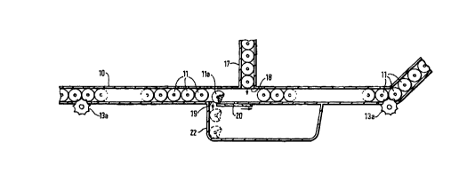
Figure 1 shows a further branch 17 in the guide 10, for repleni~hing the
guide 10 with members 11. Branch 17 may be con~tit-te~ as a spring-
loaded store of members 11 separated in normal use of the apparatus from
o the rem~intler of guide 10 by a moveable wall shown schem~ic~lly at 18
in Figure 1. If it is necessary to increase the number of members 11
within the guide 10, the wall 18 may be removed either by an automatic
mech~ni.~m or m~ml~lly in order to allow one or more additional members
11 to be dispensed from branch 17 into the main part of guide 10.
Figure 1 also shows a closable aperture 19 that may be employed for
selectively removing members 11 from the main part of guide 10. This
may be required, for example when a member lla becomes damaged or
broken.
In the embodiments shown, aperture 19 includes a slidable cover 20 that
may be withdrawn to one side to allow the damaged member 11a to fall
into a receptacle 22 secured to the underside of constraining guide 10.
25 Tn~te~ of a receptacle, the damaged member 11a may enter a conveyor
for removing it to a waste receptacle or repair area.
Figure 6 shows an optional portion of guide 10 formed as a downwardly
extending curve 10a. This portion of the constraining guide 10 contains
30 a pool of lubricant 23. Thus, drive-transferring members 11 passing
CA 022~l880 l998-l0-l6
W O 97/~8928 PCT/GB97/01081
through the portion of guide 10 shown in Figure 6 autom~tie~lly receive
a coating of lubricant.
Curved portion lOa need not be present if the materials chosen for the
~.
s components do not require lubrication by immersion in a liquid. For
example, the materials of the mutually engaging parts of the drive-
transferring members and the constraining guidc may be chosen to have
a low coefficient of friction. Another possibility is for the drive-
tra..sf_rring members, and/or the relevant parts of the constraining guide
o to be irnpregnated, coated or otherwise treated with a lubricant.
Downwardly directed curves lOa may be located at appropriate points
along the guide 10 in order to provide lubrication for the members 11
throughout the apparatus. If desired, the portion lOa may be automatically
or m~ml~lly refillable with lubricant, eg by means of suitable apertures.
The drive members 11 may be m~mlf~ctured from any of a variety of
materials. However, it is envisaged that a generally rigid copolymer
would be most appropriate in terms of cost and durability. The material
20 of the drive members 11 can be chosen to have a low coefficient of
friction with the constraining guide 10.
The guide~10 may typically extruded eg from aluminium or an aluminium
alloy; however, a number of other materials, including flexible materials,
25 may also be used.
The sliding cover 20 shown in relation to aperture 19 (which may also be
employed on other apertures in the apparatus) may be motorised eg by
means of a solenoid actuator itself operated under the control of an optical
30 or other sensor.
CA 022~1880 1998-10-16
W O 97/~8928 PCT/GB97/01081
The constraining guide 10 is shown in the drawings to be an open-ended
elongate device. However, it is most likely that in practical embodiments
of the invention the constraining guide 10 would constitute a closed loop
whereby to avoid the need for constant replenishment of the members 11.
s However, in applications where the drive to the transferred is
reciprocatory, it may be desirably economical to employ an open-ended
constraining guide 10 as shown.
As shown in Figure 7, the constraillhl~ guide 10 may be shaped in a
o variety of ways to accommodate obstacles, etc. in a warehouse or factory.
The constraining guide 10 may be supported at intervals, eg. by
suspenders 24 extending downwardly from the ceiling of a building.
The lubricating trough or pool 23 of Figure 6 is also visible in Figure 7.
There is, in addition, a bypass path for the constraining guide 10 so that
the drive-transferring members 11 need only enter the lubricating trough
23 as necessary. Controlling gates (examples of which are described
hereinbelow) may be employed selectively to divert the drive-transferring
20 members through the lubricating trough 23 as desired.
Figure 8 shows some further ways in which the constraining guide 10 may
be formed. As shown at 25a and 25b, the constraining guide may be
formed into coils for encircling a further component eg. a sensor for
detecting the presence of the drive-transferring members 11.
The drive member 13a is shown schematically protruding through the wall
of constraining guide 10 in Figure 8.
30 Figure 8 also shows a branch 27 in the constraining guide, included for
CA 022~1880 1998-10-16
W O 97138928 PCT/GB97101081
the purpose of repleni~hing the constraining guide 10 with drive-
transferring members 11 as necessary.
Gate members 28 protruding through the wall of constraining guide 10 in
~.
s the vicinity of junction 27 are laterally slideable selectively to open and
close the junction 27 and thereby allow one or more fresh drive-
transferring members 11 to fall into the constraining guide 10.
Similar gate members may be instal}ed at a further junction 29 for the
purpose of se~ectively removing drive-transferring members 11 from
constraining guide 10.
A detector of fractures or other failures in the drive-transferring members
11 may be operative at point F in Figure 8 to cause opening of the
s junction 29 and ejection of drive-transferring members when faults in the
drive-transferring members 11 are ~letec~ed.
Gate members 28 moveable for selective interposing in the paths of the
drive-transferring member 11 may also be supplied at branches such as
20 30. Computer control of the gate members permits guiding of the drive-
transferring members along a selected branch of constraining guide 10.
Figure 9 shows a specific example of this form of the invention, in a
garment distribution warehouse. A plurality of garment hangers 32 are
2s secured to the drive-transferring members 11 via the elongate slot 13. A
- junction such as 27 of Figure 8 allows repleni~hment of drive-transferring
members as necessary. A further junction such as 30 allows diverting of
the garments to a predetermined destination.
If desired, the drive-transferring members may be encoded as described
CA 022~1880 1998-10-16
W O 97/~8928 PCT/GB97/01081
12
in detail below in order to predeterrnine their path along the constraining
guide 10.
In the Figures 10, various forms of the constraining guide 10 and drive-
5 transferring member 11 are shown.
In Figure 10a, constraining guide 10 is an elongate, hollow, square sectionmember having an elongate slot in its lower face.
o In Figure lOb, constraining guide 10 comprises an inner, elongate, hollow
tubular member 33 surrounded by an outer such member 34. Elongate
slot 13 passes through both tubular members 33 and 34. Thus it is
possible to employ drive-trallsfellh~g members as shown having one or
more downwardly projecting portions 35.
In the preferred embodiment, the inner tubular member 33 has a low
coefficient of friction with the parts of the drive-transferring members 11
with which it is in contact. Outer tubular member 34 is ~refel~bly of a
rigid material, and as shown in Figure lOc may be armoured or otherwise
20 strengthened.
The drive-transferring members 11 may in this embodiment comprise a
pair of rollers 37 spaced from one another and mounted on a common axle
38. A central member 39 of approximately rectangular shape occupies the
25 space between the rollers 37. Axle 38 passes through an aperture in
central member 39.
Downwardly projecting member 35 is releasably secured to a portion of
central member 39 extending a short distance beyond slot 13.
CA 022~1880 1998-10-16
W 097/38928 PCT/GB97/01081
Downwardly projecting member 35 includes an aperture for receiving eg.
the hook of a garment hanger 32. Downwardly projecting member 35 is
- encoded eg. by means of a bar code 40, by implanting of a radio
fre~uency identification tag or in another optical, audible or otherwise
tr~n~mi~sible manner.
This embodiment of the invention is of parlicular use during product
m~ml~a~ture and distribution. On m~mlf~cture of a garment, it is hung on
ih~nger 32 the hook of which is inserted into the aperture of a member
0 35. This member 35 may then remain uniquely associated with the
product on hanger 32 during its transport via an apparatus according to the
invention to eg. the interior of a lorry, for subsequent distribution to a
warehouse or retail unit.
During this process the bar code or other code 40 may be read
periodically to ensure correct routing of the drive-transferring member to
which the downwardly projecting member 35 is secured. Such routing
may be achieved through operation of the gate members 28 described
hereinabove in the apparatus of the invention.
When the garment reaches a final or intermediate destination, the
downwardly projecting member 35 may be removed from the drive-
tralls~ g member. In the embodiment shown this is achieved through
use of a slidable dovetail joint, but other methods of releasably securing
25 the downwardly projecting member may also be employed.
After removal of the downwardly projecting member 35, the drive-
transferring member 11 to which it was formerly attached may be recycled
within the constrair~ing guide for receipt of another downwardly projecting
member 35; alternatively the drive-transferring member 11 may be passed
CA 022~1880 1998-10-16
W O 97/38928 PCT/GB97101081
14
to a reservoir before subsequent use.
Figures 10e and lOf show alternative profiles for the constraining guide
10.
Figure 10f also shows a ball and socket ~oint 35a for connection of the
downwardly projecting member 35. Such a joint perrnits rotation about
a vertical axis. This may be of benefit in some manufacturing and
distributing environments.
In the Figure 10b embodiment, each drive-transferring member 11
includes a radio frequency identification tag 42 that remains secured to the
drive-transferring member 11 after removal of the bar coded downwardly
projecting member 35 as shown. Such an arrangement perrnits controlled
recycling of the drive-transferring members 11.
Figure 1l shows an alternative form of the gate members 28 controlling
the flow of drive-transferring members in the constraining guide.
20 In this arrangement the gate 28 comprises a blade 43 slidably mounted via
an elongate slot 44 on a pillar 45 itself rigidly secured relative to the
constraining guide 10.
A connection member 46 interconnects blade 43 and slot 44.
A bar code reader 47 is mounted forwardly of pillar 45 for reading bar
codes associated with the drive-transferring members 1 l . In this case, the
drive-transferring members are all spherical and have the relevant bar
codes printed on their bodies.
CA 022~1880 1998-10-16
W O 97/38928 PCT/GB97/01081
The spherical members may be weighted to ensure that the bar codes are
correctly oriented.
The blade 43 may be interposed under the action of eg. a solenoid or
-
s other motive device when the bar code reader deterrnines that the branch
10 of Figure 11 is to be closed, and that the drive-transferring members
are to travel under the influence of a driven member 13 along the branch
lOb.
o The bar code reader 47 may of course be linked to a suitable control
device such as a microprocessor.
In Figures 12a and 12b, there is shown an alternative form of the
constraining guide. This constraining guide comprises (in the embodiment
shown) four rod-like members 50 that extend parallel to one another in a
square pattern, to define a comparatively open cage for constraining the
drive-transferring members 11 that are again in this embodiment spherica}.
In this embodiment the drive-transferring members may respectively be
20 secured to a load support 51 that engages the associated drive-transferring
member via the space between t~vo adjacent rod-like members 50. In such
an embodiment, the suspender 24 for the constraining guide 10 may
encircle the rod-like members 50 as shown and may include one or more
apertures 24a,24b permitting passage therethrough of the support member
2s 51 and any goods 52 supported thereby.
An alternative, downwardly projecting support member 51a is also shown
in Figures 12a and 12b. Aperture 24b in suspender 24 accommodates
travel of such a member.
CA 022~1880 1998-10-16
W O 97/38928 PCT/GB97/01081
16
In Figure 13, there is shown a three dimensional array of constraining
guides 10, installed within a warehouse 54.
Portions 10" 102, 103, 104, etc of the constraining guide 10 are open
ended on one side of the three dirnensional array of constraining guides,
for receipt of eg. garments or other goods transported by the apparatus of
the invention. Such goods may be delivered eg. by lorry or other vehicle
from a factory or another distribution centre.
o The goods transported on the apparatus fed into the array via the open
ended portions may be transported to any suitable storage point within the
three dimensional array as in-lie~t~cl scheln~ti~lly. If desired, spiral
portions 10'' of the constraining guide may be employed to raise or lower
goods as desired. The use of such spiral portions brings the goods into
15 contact with a plurality of further parts of the array.
Crossings of portions of the constraining guide 10 may include junctions
such as 27,29 or 30 previously described, in order to provide for routing
of individual goods to any preferred location within the array in
20 dependence on the encoding of such goods.
Further, open-ended portions of the constraining guide 10'l, etc may be
provided in a dispatch area preferably located on the opposite side of the
three dimen~ional array. The goods to be dispatched may be transported
25 into vehicles such as those shown in Figure 13 for onward dispatch to
further distribution centres, retail units or other locations.
A computer control system may be employed to ensure routing of the
goods within the three dimensional array, according to encoding of either
the drive-transferring members 11 or members attached thereto. This will
CA 022~1880 1998-10-16
WO 97/~8928 PCT/GB97101081
17
allow significant reductions in staffing levels at warehouses.
Referring now to Figure 14a, a vehicle 55 such as that shown in Figure
13 is shown in greater detail.
Vehicle 55 includes formed therein a further three dimensional array of
the constraining guides 10. In the embodiment shown, the constraining
guides perrnit vertical movement of interme~i~te, connecting bars 56 and
hor~ tal movement of such bars along the interior of the vehicle, as
o desired.
Two portions 1 lOa and 110b are hingeably secured to the three
dimensional array formed within the lorry. The hingeable portions 1 lOa
and 110b may be hinged outwardly from an initial, flush position to
5 protrude from the rear of the vehicle for engagement with the outer, open
ended portions 10'l, 10'2, 10'3, 10'4 of the three dimensional array in the
warehousing building 54.
If desired, the hingeable portions 110a, 1 lOb may be secured to or formed
20 within the rear doors of the vehicle.
Alternatively the portions 110a, 110b may be slideable into and out of the
vehicle. In such cases the portions 110a, 110b retain the orientation
shown throughout their movements.
The free ends of the portions 10'" 10'2, etc include gate members 57 that
in the embodiment shown are simple pins inserted through aligned holes
formed in opposite sides of the constraining guide 10, to prevent the drive-
transferring members 11 from falling out of the apertures at the ends of
30 the constraining guide portions 10' l, 1~'2~ etc.
CA 022~1880 1998-10-16
W O 97/~8928 PCT/GB97/01081
18
If desired, flexible portions may be included in such parts of the
constraining guide to ensure mating of the hingeable portions 1 lOa, 1 lOb
with the corresponding junctions defined at the free ends of the
constraining guide.
s
The hingeable portion and/or the free ends 10'" 10'2, etc. may if
necessary include clips or other means of securing them to the portions of
constraining guide that abut them on manoeuvring of the vehicle 55 to a
loading or unloading position.
Although the arrangement shown in Figure 14a concerns loading of goods
onto a vehicle, it will be appreciated that a sirnilar arrangement may ~e
employed for unloading of the vehicle when it reaches its destination.
The vehicle 55 may include a microprocessor or other controller device
for routing the garments, eg. as supported on the bars 56, within the
vehicle in dependence on encoding of the drive-transferring members 11
or further members secured thereto.
20 Such an arrangement may permit org~ni~tion of goods within the vehicle
as it travels, thereby speeding unloading of goods at the vehicle's
destination.
An alternative array of constraining guides in a vehicle 54 is shown in
2s Figure 14b.
In this arrangement the deck of the vehicle contains a grid-like array of
interconnected constraining guides 10, the interconnections including
junctions as necessary such as junctions 27, 29 and 30 of Figure 8.
CA 022~1880 1998-10-16
W O 97/38928 PCT/GB97/01081
19
Figure 14d shows the floor plan of the vehicle, that optionally includes
side doors that permit rapid unloading of the vehicle. The side doors
minimi~e the movement of goods needed within the vehicle to achieve
speedy unloading.
This arrangement is intended to support a pallet such as pallet 58 of
Figure 14c.
Pallet 58 includes a plurality of selectively downwardly moveable
o members 59 for engagement with selected drive-transferring members 11
in the array of constraining guide 10.
Depending on encoding of either the pallet or the drive-transferring
memberst the pallet may drivingly engage predetermined drive-transferring
member 11 in order to move the pallet within the vehicle.
If desired, one or more grid squares of the array shown in Figure 14b
may be left blank to provide room for manoeuvring the pallets within the
vehicle.
Alternatively, a grid extension 60 (optionally supported on leg 61) of
constraining guide members 10 may project from eg. the rear of the
vehicle to provide such space for manoeuvring.
25 Figure 14b also shows an equivalent array of constraining guides 10'" at
- an upper level within the body of the vehicle 54, for manoeuvring pallets
58 in a second tier within the vehicle.
If desired, the entire array of upper constraining guide 10''' can be height-
30 adjustable on eg. suitable hoist motors within the vehicle 54.
CA 022~1880 1998-10-16
W O 97/~8928 PCT/GB97/01081
The computer control may if desired be operable on the upper tier of
drive-transferring members as well.
Furthermore, suitable extensions 60" may be provided to perrnit
5 manoeuvring of the pallets 58 on the upper tier.
As in the embodiment of Figure 14a, the constraining guides 10 of Figures
14b and 14c may if desired be connectable to eg. the free ends 10'l, 10'2,
10'3 as shown in Figure 14a.
Referring now to Figures l5a and l5b, there is shown a reservoir 63 of
encoded drive-transferring members 11 for use in a warehouse, factory or
vehicle based environment such as those of ~igures 13 to 14.
lS As is shown in detail in Figure 15b, the reservoir 63 is subdivided into a
plurality of compartments. Each compartment contains a plurality of
drive-transferring members 11 encoded in a predetel~ ed way, eg. to
indicate to a control device controlling operation of the apparatus of the
invention the destination of goods to be carried by the apparatus. This is
20 shown schematically in Figure 15a.
A plurality of gate members such as gate members 28 as described
hereinabove, may selectively control the feeding of drive-transferring
members into the constraining guide 10. This may be achieved eg. in
2s dependence on intervention by the operator of a garment m~nnfacturing
or fini.ching machine may on completion of each garment indicate the kind
of drive-transferring member 11 (in terms of its encoding) to be added to
the constraining guide 10, prior to attachment of the garment hanger 32
for the most recently completed garment thereto. In this way, within
30 seconds of their manufacture or fini~hing the garments are associated with
,-- , . . _ . . .
CA 022~1880 1998-10-16
WO 97/38928 PCT/GB97/01081
drive-transferring members of the apparatus of the invention that are
encoded as to their destinations. Such encoding may be carried with the
garrnents throughout their journeys to final destinations, such journeys
possibly embracing travel t'nrough warehouse-based systems as shown in
s Figure 13 and in vehicles such as those of Figures 14.
Referring now to Figure 16, there is shown a flatbed conveyor powered
by a pair of constraining guides 10 according to the invention.
o Flatbed conveyor 63 includes a plurality of horizontal slats or plates 64
secured one adjacent another on a pair of parallel, mllnl~lly spaced
constraining guides 10 according to the invention.
Each of the slats or plates 64 is ~li(lingly engaged on its underside with
one or more of t'ne drive-trall~re~ g members 11 of one or both the
constraining guides 10 shown in Figure 16.
The slats or plates 64 may be linked together eg. by means of sliding
links, or may be mllnl~lly disconnected from one another.
The Key advantage of using constraining guides according to the invention
in the Figure 16 embodirnent is that the constraining guides may be driven
at different speeds from one another when it is required to drive the
flatbed conveyor 63 around a bend as shown.
A branch lOa of the constraining guide stands at the infeed to the bend
negotiated by the outer constraining guide. Constraining guide branch lOa
feeds additional drive-transferring members 11 into the constraining guide,
in order to permit faster travel of the outer part of the flatbed conveyor in
the vicinity of the bend. At the terrnination of the bend, a further branch
CA 022~1880 1998-10-16
W O 97/38928 PCT/GB97/01081
10b of the constraining guide 10 may remove the excess constraining
guides in order to permit the two constraining guides 10 to follow a
straight line path at the same speed.
s For the avoidance of doubt, in the Figure 16 embodiment, the flatbed
conveyor 63 travels in the direction of the arrows C.
Suitable gates such as gate members 28 may be employed at the junctions
between the branch portions 10a and 10b dll~i the main constraining guide
o forming the outer part of the curve.
As shown in Figure 17, the slats or plates 64 may be constructed in two
portions 64a, 64b. One of the two portions 64a may be hollow for
receiving the free end of the other portion 64b of the slat 64. A resilient
5 connection in-lic~te(1 schem~tir-~lly by spr~llg 65 may permit resilient
compression and/or extension of the elongate length of each slat or plate
64. This allows the slats or plates to accommodate changes in the spacing
between the two constraining guides 10 visible in Figure 17.
20 Thus the apparatus of the invention permits construction firstly of a
conveyor that is able to negotiate bends through use of variable speed
drives as shown in Figure 16; and secondly of a conveyor the width of
which may vary in dependence on the spacing between the pair of
constraining guides 10.
2s
Hitherto it has not been possible to devise a powered conveyor the width
of which varies at different points about its travel.
Figure 18 shows in plan view a typical conveyor layout for use eg. in a
packing area or product fini~hin~ area of a factory or warehouse.
CA 022~1880 1998-10-16
W O 97/~8928 PCT/GB97/01081
23
The constraining guides 10 are shown sçh~m~ti~lly, as are the branches
lOa and 10b of Figure 16. The slats or plates 64 of the conveyor are
omitted from Figure 18 for clarity.
5 A further layout of constraining guide members 10 is shown in Figure 19.
In this figure there is a main constraining guide loop 10 driven by a main
drive member 13 driven by a motor (not visible in Figure 19).
A branch loop lOc may selectively divert drive-transferring members 11
0 from the main loop 10 and may pass through~eg. a protective wall 66 into
a hazardous area, a clean room, or other processing area 67 to which
human access is normally denied.
In the embodiment shown, there is a single constraining guide (as
compared with the parallel pair of constraining guides of eg. Figure 18),
that in the processing area 67 passes about the periphery of a rotatable
table or dais 68. Contact of the drive-transferring members of the branch
loop constraining guide lOc with a suitable surface formed in the
periphery of the rotatable dais 68 may cause driven rotation thereof. If
20 n~cess~ry, a further driven member represented sch~m~tic~lly at 13c may
be provided to power the drive-transferring members around the branch
loop lOc to achieve this.
The drive-transferring members 11 may transfer their drive in other ways
25 as desired within the processing area 67.
Referring now to Figure 20a, there is shown a vehicle comprising a
framework 70 constituted predomin~ntly of constraining guides 10 of
apparatus according to the invention.
CA 022~1880 1998-10-16
WO 97/38928 PCT/GB97/01081
24
The constraining guides 10 of the framework 70 are in the embodiment
shown each formed as parallel, m~ lly spaced polygonal shapes rigidly
interconnected by struts 71 disposed at intervals about the periphery of the
polygonal shape visible in Figure 20a.
Each constraining guide 10 includes a junction 72 that may be similar to
those eg. on the hingeable portions of the constraining guides of Figure
14, for connection with further constraining guide portions 10 conveying
goods from eg. a factory or warehouse.
In the embodiment shown, such constraining guides extend in parallel, and
pairs of drive-transferring members 11 in the respective parallel
constraining guides are interconnected by rigid rods 72 that each have
suspended therefrom a goods tray 73.
It will be apparent that by conn.octing the constraining guides 10
co~ g the bulk of frame 70 of the vehicle of Figure 20a, the goods
trays 73 may be conveyed onto the vehicle for rotation either by means of
a motor or by hand about the periphery of frame 70. This permits eg. a
20 worker shown schematically at 74 to fill or empty the trays as desired.
Figure 20b shows one way in which the rods 72 may be received in the
drive-transferring members 11. In Figure 20b the elongate slot 13 of the
constraining guide 10 faces horizontally to receive the horizontally
25 extending rod 72. If necessary, a detent may be employed to retain the
end of the rod 72 in an aperture formed in the drive-transferring member
11 that in the embodiment shown is formed as spherical element.
In the Figure 20b embodiment, the portion of the rod 72 interconnecting
the two drive-transferring members is dispensed with. Interconnection of
,
CA 022~1880 1998-10-16
W 097/38928 PCT/GB97/01081
the drive-transferring members 11 is achieved through rigidity of the tray
73.
Figure 20a also shows a cap 76 that may be used to close the free end of
s the constraining guides 10 when the vehicle is moved away from the
position shown. The vehicle includes wheels for this purpose.
Figures 21a and 21b show the apparatus of the invention configured as a
motul oO.
In this embodiment, a plurality of the constraining guides 10 extend
parallel to one another and are each looped about respective, spaced
rollers 81, 82.
As shown in Figure 21b, in this embodiment slot 13 is omitted from
constraining guide 10. Instead, the wall of constraining guide 10 is
m~mlf~r.tllred from an open mesh-like material that permits contact
between the drive-transferring members 11 and further members exposed
outside the constraining guide 10.
It will thus be appreciated that if roller 81 is driven eg. by means of
electric motor 83, the rotation of ro}ler 81 is transferred to linear motion
of the drive-transferring members 11. Since the drive-transferring
members travel from roller 81 to roller 82, as they pass over roller 82
25 their drive is transferred to roller 82 that is thereby caused to rotate.
A series of brake members 84 may be selectively brought into contact with
the constraining guides 10 shown in Figure 21b. The lowermost brake
member 84e may be arranged to contact only the extreme left hand
30 constraining guide visible in Figure 21b; the next uppermost may be
CA 022~1880 1998-10-16
W O 97/38928 PCT/GB97/01081
26
arranged only to contact the constraining guide immediately to the right
thereof, and so on, whereby on lowering the brake members downwardly
in the direction of arrow B in Figure 21 the constraining guides may be
successively slowed or brought to a stop. This in turn reduces the energy
s transferred to roller 82 in a progressive manner, thereby slowing or
stopping it as desired.
The brake members 84a may be mounted on a lever or may be actuated
by means of eg. a solenoid or other mo~ , if necessary in dependence on
o control signals generated in eg. a microprocessor or other controller.
Each brake member may include a brake pad 86 (best shown in Figure
21b) offset laterally from the brake pad in a neighbouring brake member
whereby to dedicate a given brake member 84 to the slowing or stopping
S of the drive-tra~rell~g members in a predetermined constraining guide
10.
As shown ~n Figure 21b, the drive-transferring members 11 preferably
have a rigid central zone surrounded by a deformable outer coating.
The mesh-like outer covering of the constraining guides 10 shown in
Figures 21 may for example be supplied for safety purposes over the rods
50 of Figure 12, thereby preventing articles from becoming entrained or
trapped in the constraining guide thereof. In such an arrangement, the
2s mesh may be of a closer weave whereby to prevent access of eg. human
digits to the drive-transferring members 11.
Referring now to Figure 22, there is shown a window 88 formed in a
portion of a constrainmg guide 10 according to the invention. Window
88, which may be covered eg. by a perspex material, permits reading of
CA 02251880 1998-10-16
2ri7
optic~l CIlCOdi~g i~forma~o~ tllat is ~ directly ,~~n the dr.
~sferring member 11 ~,isiblc ~ e 22. Such e~o~ for~a~o
~which ma~ be in the form of b,~r codes or ot~cr opti~al eodes~ n~ay ~e
pri~t~d direc~ly ~nt~ the drive-t:ra~sfemn~r member, or m~ c~Tie~
e~. a ~icke~ ~ed ~ the driYe-~ans~erri~g member.
The windo~J ~8 m~ ~lso permit eg. t~e rea~ling of a radio fre~ue~cy
identificauon r~g secured to the drive-~nsferr~o member ~0
'rhe ~e~der; ~or the bar c~ andinr r~dio ~e~ nc~ or o~er
~dentif;~rio;l t~oS, r~ay ~f desired be ~nciosed ~tl~ coil~ 25 o~ rhe
cons~a~g guide 10 as sho~ iIl Figure 8. Thus the code readi~O
app ~htllS may ~e protected ag~t damage 3nd c~rt~min~tTon, and the
windc)~s 88 may also be protected ~a~st dam~_e. When the ~dows
i~ 88 dc nol i~clude a e~,er su~h ~ heet o~' perspe.~c or olass, thei~
po.~itionino ~II. ;he n~er fac~ of a coil such as c~ils 25 or ~a ~re~ents
T~d~iertent ~ ~ct of other objec~s wi~ the dri~e~ ~g members
11. Thus rb~ s~fety of tl:le app~ra~s ~s :lssurcd.
Figuro ~3 ~h )ws ~ ~lternative desiorl of Lh~ drive-tralls~erri~ mcLnber l 1
shown e~. in Figurcs lO. In this e~bod~ment eh~ rolI~rs 37 h;l~e a
ro-~,hPn~ cr serrated ou~er p~rrphery ~or g~ippin~ the int~nor ol dle
c~ ~ide 10.
2s Figure 23 a!so sha~s one posslble lo~ati~n for the r~dio li~uency
idenrificatio~! lag 42. As sho~n, the tag is iocated in :he hub o~ the aYle
38.
In Figure 241 there is shvwn an arr~g~ment by whic~ the ~a~s ~6 vf rne
,o Figure 14~ a] rangement may be supported relati~e c~ the drive-~ransferr~g
~ME~=, ,iE-- 1
CA 022~1880 1998-10-16
W O 97/~8928 PCT/GB97/01081
28
members 11. As shown, each drive-transferring member 11 has
projecting outwardly thelerlo~ll a cup 89 that protrudes beyond the slot 13
of constraining guide 10 in a horizontal direction. Each bar 56 has a
reduced diameter portion 56a at either end that is receivable under the
s action of gravity in the cup 89, whereby to support the bar 56 at either
end. When the drive-transferring members 11 are computer controlled,
it is possible to m~int~in the bars 56 horizontal throughout their travel.
Any of the optional embodiments described herein in relation to Figures
o 1 to 24 may be employed on their own, or in conjunction with others of
the optional embodiments as desired.
The components of the invention may be manufactured from a variety of
materials, as appropriate. For example, the components may be
lS m~m-f~ctllred from materials suitable for use in dirrerellt industries such
as the food industry, chemical processing industry and the pharmaceutical
industry. Corrosion free (eg. non-metallic) materials may be employed as
appropriate.
20 The constraining guides 10 may be m~nllf~tured from flexible materials
or rigid material as desired.
Self-lubricating materials may also be used as appropriate. For example,
sintered materials that dispense lubricants as they wear may be employed
25 for the interior of the constraining guide 10 and, optionally, for the drive- transferring members 11.
The windows 88 may also be used to indicate the completion of actions
eg. in process plant. For example, the presence of an encoded drive-
transferring member in a chosen window 88 may indicate the the lapsing
CA 02251880 1998-10-16
WO 97P8928 PCT/GB97/01081
29
of a predetermined amount of time from the completion of a previous
process, by virtue of travel of the drive-transferring members 11 a
predetermined distance along the constraining guides 10.
Reservoirs for receiving drive-transferring members 11 from and
supplying drive-transferring members 11 to the constraining guides 10
may be operatively connected to the constraining guides 10 at suitable
locations, as desired. In the case of the vehicles of Figures 14, the
reservoil~ may be located eg. under the floor of the vehicle, where there
lO is conventionally a ~ignificant "dead" space.
~ .