Note: Descriptions are shown in the official language in which they were submitted.
CA 02252046 1998-11-23
HYDRAULICALLY POWERED BALER PLUNGER DRIVE MECHANISM
Backgiround of the Invention
The present invention relates to drive mechanisms for plungers of balers for
making
parallelepiped bales, and more particularly, relates to hydraulically powered
plunger drives.
It is common baling practice to use a reciprocating plunger to compact charges
of cut
vegetation within a baling chamber. Reciprocation of the plunger is usually
effected either
by a tractor power take-off driven mechanism including a rotating crank
coupled to the
plunger by a connecting rod, or by a hydraulic cylinder having its piston rod
coupled directly
to the plunger. An example of a typical power take-off driven mechanism is
illustrated in
U.S. Patent No. 4,524,574, issued 25 June, 1985, while an example of a typical
hydraulically
driven plunger is illustrated in U.S. Patent No. 4,202,262, issued 13 May,
1980.
The simplicity of using a hydraulic piston and cylinder unit (hydraulic
actuator), as
shown in the above-identified patent, for driving a plunger is desirable, but
this structure has
the drawback of requiring a hydraulic actuator of substantial length in order
to produce the
desired travel of the plunger and of requiring a hydraulic pump having a
displacement
chosen for supplying the volume of fluid necessary for stroking the plunger
drive actuator at
the speed required for baling operation.
Summary of the Invention
According to the present invention there is provided an improved hydraulically
powered mechanism for driving the plunger of a baler for making parallelepiped
bales.
An object of the invention is to provide a drive mechanism, for a baler
plunger, which
incorporates an extensible and retractable hydraulic actuator connected to a
slider-crank
linkage such that for a given stroke of the actuator the plunger will be moved
approximately
twice the stroke distance.
Yet another object of the invention is to provide a drive mechanism, as set
forth in
the immediately preceding object, wherein the moment arm between the actuator
and the
plunger increases as the plunger reaches its fully extended position.
Still another object of the invention is to provide a drive mechanism, as set
forth
above, which is relatively compact in a direction extending longitudinally of
the baling
chamber.
Another object of the invention is to provide a plunger drive as set forth in
the above
objects wherein a variable displacement, reversible pump is used for supplying
fluid to the
hydraulic actuator and is controlled in such a way that there is a dwell in
the plunger motion
which takes place at the point where the plunger is fully extended.
These and other objects will become apparent from a reading of the ensuing
description together with the appended drawings.
CA 02252046 1998-11-23
Brief Description of the Drawincts
FIG. 1 is a somewhat schematic, left side elevational view of a baler for
producing
rectangular bales and incorporating a plunger drive mechanism of the present
invention,
with the bale case crop feed duct being shown in section and with the plunger
actuator fully
extended and the slider-crank mechanism and the plunger shown fully retracted.
FIG. 2 is a view like FIG. 1 but showing the plunger actuator fully retracted
and the
slider-crank mechanism and the plunger fully extended.
FIG. 3 is a side elevational view of an optional arrangement of the plunger
actuator
and slider-crank mechanism showing the slider crank mechanism and the plunger
retracted,
as in FIG. 1, but, in this arrangement, also showing the actuator fully
retracted.
FIG. 4 is a schematic of the electro-hydraulic circuit used to control
operation of the
plunger actuator.
FIG. 5 is a graph showing the plunger position as a function of time during
one cycle
of the plunger.
Description of the Preferred Embodiment
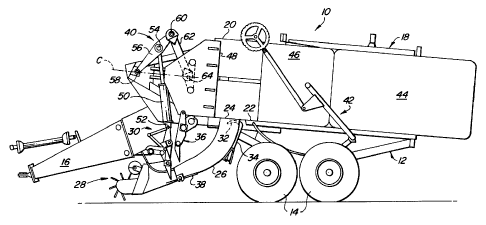
Referring now to the FIGS. 1 and 2, there is shown a baler 10 for making
parallelepiped bales and including a frame 12 supported on a tandem set of
ground wheels
14. A tongue 16 is fixed to and extends forwardly from the frame 12 and is
adapted for
being attached to a prime mover, such as an agricultural tractor (not shown)
equipped with a
power take-off shaft for supplying power for driving various driven components
of the baler.
A baling chamber or bale case 18 of rectangular cross section is defined in
part by upper
and lower walls 20 and 22, respectively, with the lower wall 22 being provided
with a crop
inlet 24 to which is attached a curved in-feed duct 26 which serves as a pre-
compression
chamber, as described below. A crop pick-up and center-feed auger assembly 28
is
provided ahead of the duct for picking up a windrow of crop from the ground
and delivering it
to a packer fork assembly 30 which acts to pack crop into the duct 26 until a
charge of a
pre-selected density has accumulated downstream of fingers 32 of a backstop
device 34,
the device 34 being pivotally mounted for movement between a blocking
position, wherein
the fingers 32 project into the duct 26 in the vicinity of the inlet 24 (FIG.
1 ), and a feed
position) wherein the fingers are withdrawn from the duct 26 (FIG. 2) to
permit the charge of
crop material to be stuffed into the baling chamber 18 via the inlet 24 by a
stuffer fork
assembly 36. Located in a lower front location of the duct 26 is a pivotally
mounted, spring-
loaded door 38 that pivots, in response to crop material located in the duct
achieving a
2
CA 02252046 1998-11-23
desired density, to effect energization of an electrical control circuitry
(not shown) which
actuates appropriate drive couplings which first cause the backstop device 34
to rotate so as
to withdraw the fingers 32 from their blocking position shown in FIG. 1, and a
then to actuate
the stuffer fork assembly 36 such that forks thereof sweep through the duct 26
and move
the charge of material into the baling chamber 18. Once the charge of crop
material is
stuffed into the baling chamber 18, a plunger mechanism 40, which is mounted
to a forward
location of the frame 12 and forms the subject of the present invention
described in further
detail below, is operated, in controlled sequence after operation of the
feeder fork assembly
36, to move the material rearwardly in the chamber 18 where it is compacted
into a column,
as is well known in the art. Upon the column of compressed crop material
reaching a
preselected length, a twine-delivery needle assembly 42, including a plurality
of curved
needles, is actuated to deliver a plurality of strands of twine respectively
to a plurality of
knotters (not shown) which act to tie lengths of twine about the preselected
column length to
form a bale 44 that is then ready for discharge, which will occur upon it
being forced from
the rear end of the chamber 18 by a bale portion 46 as it grows in length upon
new charges
of crop being stuffed into the chamber.
Returning now to the details of the plunger mechanism 40, it can be seen that
the
latter includes a plunger 48 mounted for reciprocating in the baling chamber
18 between a
retracted position forwardly of the inlet 24, as illustrated in FIG. 1, and an
extended position
rearwardly of the inlet 24, as illustrated in FIG. 2. This movement of the
plunger 48 results
in charges of crop, fed into the chamber 18 from the duct 26, being compacted
against a
column of crop material including the partially formed bale 46 and/or the
completed bale 44.
The plunger mechanism 40 further includes an extensible and retractable
actuator 50, here
shown as a double-acting hydraulic cylinder and piston unit, having its
cylinder end pivotally
anchored, as by pin 52, to the frame 12 at a location above the packer
assembly 30. The
rod end of the actuator 50 is pivotally coupled, as at a pin 54, to a location
intermediate
opposite ends of a crank arm 56 having its forward end pivotally attached to
the frame 12 at
a location 58. A rear end of the crank arm 56 is pivotally attached, as by a
pin 60, to a
forward end of a connecting rod 62 having its rear end pivotally attached, as
by a pin 64, to
a central location of the plunger 48. It is here noted that the connection
pins 58 and 64 are
located along a line of centers C which lies along or approximately lies along
a central,
longitudinal axis of the baling chamber 18. This results in the reaction force
of the crop
acting on the plunger 48 being substantially removed from the actuator 50 when
the crank
3
CA 02252046 1998-11-23
arm 56 and connecting rod 62 are located along the line C, as is the case when
the plunger
48 is in its fully extended position shown in FIG. 2. It is further noted that
the crank 56 and
connecting rod 62 could each be constructed of a pair of laterally spaced
links. The actuator
50 would then be connected to the pin 54 at a location between the pair of
links forming the
crank arm 56. The pin 64 would then extend between the pair of links forming
the
connecting rod 62 and pass through a bracket forming part of the plunger 48.
Thus, it will be
appreciated that the plunger 48 forms the slider of a slider-crank mechanism
including the
crank arm 56 and connecting rod 62. Although it doesn't move over center, the
linkage
defined by the crank arm 56 and connecting rod 62 could be called a toggle
mechanism or
linkage. Further, while the preferred embodiment shows the actuator 50 coupled
to crank
arm 56 at a location between opposite ends of the arm, the actuator 50 could
be coupled at
any location between the crank arm pin 58 and the connecting rod pin 64, for
example the
actuator 50 could be coupled at the pin 60 or to a point along the length of
the connecting
rod 62, with the operation still being in a beneficial manner as compared to
the prior art
devices of the type having the actuator coupled directly to the plunger.
In any event, it is important to note that the leverage exerted by the crank
arm 56
and connection rod 62 on the plunger 48 will increase as the actuator 50 moves
from its fully
extended position (FIG. 1 ) to its fully retracted position (FIG. 2). This
matches exactly the
force requirements of the system since the plunger 48 will meet with increased
resistance as
it moves to the rear in the baling chamber 18 for compacting a charge of crop
material
against the compressed column of crop contained in the chamber. Not only does
the crank
arm 56 and connecting rod 62 function to increase force output at the
connection with the
plunger 48 as the plunger moves rearwardly, but they also act to move the
plunger 48
rearwardly through a distance which is approximately twice that of the stroke
of the
hydraulic actuator 50. Accordingly, the length of the actuator 50 and the
displacement of
the pump supplying fluid thereto can be minimized, thus resulting in a cost
savings over the
prior art system where the length of the actuator is determined by the
distance through
which the plunger must be moved when traveling between its fully retracted and
extended
positions.
Referring now to FIG. 3, there is shown a plunger mechanism 40' which differs
from
the mechanism 40 by having the crank arm 56 and connecting rod 62 located so
as to form
a mirror image of their positions shown in FIGS. 1, relative to the line of
centers C. The
most significant result of this rearrangement of the arm 56 and connecting rod
62 is that the
4
CA 02252046 1998-11-23
actuator 50 is now fully retracted when the plunger 48 is fully retracted, as
shown. Thus,
extension of the actuator 50 causes extension of the plunger 48 and
pressurized fluid routed
to the cylinder end of the actuator will act on the larger surface area of the
piston, it being
noted that the area occupied by the rod on the rod side of the piston is not
available for
doing work.
Referring now to FIG. 4, there is shown an electro-hydraulic control circuit
70 for
controlling operation of the plunger actuator 50. Specifically, the control
circuit 70 includes a
reversible, variable displacement pump 72 having first and second ports
respectively
coupled to the cylinder and rod end of the actuator 50 by supply/return
conduit 74 and 76.
The pump 72 includes a swash plate 78 movable, by a hydraulic control here
indicated as a
piston 80, in increasing amounts to opposite sides of a centered neutral
position to effect
increasing fluid displacement, the piston 80 being shown in a centered
position where it
holds the swash plate 78 in a neutral position, zero- displacement position.
Control of the
piston 80, and hence control of the direction and displacement of fluid from
the pump 72, is
effected by a spring-centered, solenoid-operated three-position swash plate
control valve 82
having forward and reverse solenoids 84 and 86, respectively, at its opposite
ends which
are selectively energized to cause the piston 80 to be respectively shifted
increasingly
leftwardly and rightwardly from its illustrated neutral position to
respectively effect increased
fluid displacement to the pressure/return lines 74 and 76 so as to effect
retraction and
extension of the hydraulic cylinder 50. Specifically, energization of the
forward solenoid 84
causes the valve 82 to shift rightwardly to connect a fixed displacement pump
88 with a
base end of a cylinder containing the piston 80 while connecting the rod end
of the cylinder
to a sump 90. On the other hand, energization of the reverse solenoid 86
causes the valve
82 to shift leftwardly resulting in the pump 88 being connected to the rod end
of the cylinder
containing the piston 80 while connecting the base end of the cylinder to the
sump 90.
Replacement or charge pressure fluid is introduced into the lines 74 and 76,
respectively, by
way of a branched charge pressure line 92 containing check valves 94 and 96
which
operate so that fluid is introduced into which ever one of the lines 74 and 76
contains fluid at
the lower pressure. Coupled between the pressure/return lines 74 and 76 is a
valve
assembly 98 containing charge and high pressure relief valuing, as is well
known in the art.
Actuation of the solenoids 84 and 86 is carried out by an electrical control,
indicated
functionally at 100, containing position responsive switch elements 102 and
104,
respectively, which are actuated in response to the respective positions of
the stuffer fork
5
CA 02252046 1998-11-23
mechanism 36 and the plunger mechanism 40 so that actuation of the solenoids
shifts the
swash plate position control valve 82 in the appropriate direction for causing
desired
operation of the plunger actuator 50. Specifically, assuming the plunger 48 to
be fully
retracted and the stuffer fork mechanism to be at its stand-by position shown
in FIG. 1, the
switch components 102 and 104 will operate to effect an open circuit between a
source of
electrical power (not shown) and the valve solenoids 84 and 82. Thus the swash
plate 78 of
the pump 72 will be in its centered, zero displacement condition. Once crop is
moved into
the duct 26 and is precompressed to the desired density, the pressure plate 38
will initiate a
drive connection (not shown) to the stuffer fork mechanism 36 which will cause
the latter to
be driven to sweep its forks upwardly through the duct 26 to move a charge of
crop into the
bale case 18. The position sensing component 102 then effects operation of a
switch which
couples the valve solenoid 84 to the source of electrical power. Upon being
energized, the
solenoid 84 effects shifting of the swash plate control valve 82 so that the
pump swash
plate 78 is pivoted to effect maximum displacement of fluid to the rod end of
the plunger
actuator 50. This causes the actuator 50 to retract and move the plunger 48
rearwardly to
its fully extended position shown in FIG. 2. The position sensing component
104 then
senses condition of the plunger mechanism and operates, in response to one or
the other of
the components 48, 56 or 62 being positioned as it is when the plunger 48 is
fully extended,
as shown in FIG. 2, to effect opening of the circuit previously completed by
operation of the
component 102 and to effect closing of a circuit for connecting the source of
electrical power
to the solenoid 86. This results in the valve 82 first returning to its
centered neutral position
and then in being shifted leftwardly so that the pump swash plate 78 is
pivoted to effect
maximum displacement of fluid to the head end of the plunger actuator so that
it extends to
retract the plunger 48 to its retracted position shown in FIG. 1. Upon the
plunger 48
approaching its fully retracted position, the sensing component 104 acts to
cause the circuit
to the solenoid 86 to open so that the valve 82 once again is moved to its
centered neutral
position with the result that the swash plate 78 is once again returned to its
centered, zero
displacement position.
Operation of the position sensing components 102 and 104 when used in
conjunction with the plunger mechanism 40' of FIG. 3 is exactly the same as
when used with
the plunger mechanism 40 except that the valve 82 is reversed so that
extension of the
plunger 48 is effected in response to extension of the actuator 50 and
retraction of the
plunger 48 is effected in response to retraction of the actuator 50.
6
CA 02252046 1998-11-23
Referring now to FIG. 5, there is shown a graph plotting the position of the
plunger 48 versus time during one cycle of the plunger 48 as it moves from its
retracted
position to its extended position and then back to its retracted position. It
can be seen that
there is a relatively flat dwell segment d in the graph which occurs at the
point in the cycle
that corresponds to the time when the pump swash plate 78 is going through its
neutral,
zero displacement position as it goes from its fully swashed position, where a
maximum
displacement of fluid is occurring through the supply/return conduit 74 for
effecting retraction
(extension in the embodiment shown in FIG. 3) of the actuator 50 and extension
of the
plunger 48, to its zero-displacement position and then to its fully swashed
position in the
opposite direction for causing a maximum displacement of fluid through the
supply/return
conduit 76 for effecting extension of the actuator 50 (retraction in the
embodiment shown in
FIG. 3) and retraction of the plunger 48. This dwell d does not occur in a
plunger system
where the crank arm 56 is driven through 360° as by a gear drive, for
example. In such a
drive the displacement-versus-time graph is a pure sinusoid with only a point
at the top of
the curve representing the occurrence of the crank arm rotating past the
position where the
plunger is fully extended and returning toward the position where the plunger
is fully
retracted. The occurrence of the dwell d is thought important from the
standpoint that by
holding the compressed hay for the dwell period, here shown as being
approximately 0.8
seconds, as the compressed crop then has less of a tendency to spring back
once the
plunger moves away. This results in a denser bale being formed. Further, the
dwell period
results in the plunger 48 retaining the compressed crop out of the way for an
adequate
period of time for permitting the uninhibited passage of the needles of the
twine delivery
mechanism 42 through the bale case 18 to carry the twine to the knotters and
then to return
to its illustrated stand-by position.
7