Note: Descriptions are shown in the official language in which they were submitted.
CA 02252077 1998-10-08
-1-
DESCRIPTION
STEAM-COOLED COMBUSTOR FOR A GAS TURBINE
Industrial Field
This invention concerns a steam-cooled combustor for a
gas turbine. More specifically, it concerns a structure for
steam-cooling the exterior wall panels of the combustor,
which are exposed to very hot combustion gases.
Teahnioal Bavkground
One effective way to improve the thermal efficiency of
a gas turbine is to boost the temperature at the gas inlet of
the turbine. It is also desirable to suppress increased
emission of NOX from the combustor, which supplies combustion
gases to the turbine, and to improve the heat resistance of
the turbine and its cooling capacity.
Since the combustor is exposed to temperatures of 1500
to 2000 °C, it must be properly cooled so that the
temperature of its exterior wall panels remains in the
allowable range as it experiences thermal stress.
Generally, combustors in gas turbines are cooled by
running the air to be used for combustion along their inner
wall panels, and by forcing air inside these wall panels in
order to cool the metal components so that their temperature
is lower than that of the combustion gases.
However, if air is used to cool the turbine, the air
used for cooling and the air that leaks from the cooling
channels is released into the main gas flow. This air makes
it more difficult to improve the capacity of the gas turbine
CA 02252077 1998-10-08
-2-
and decrease the emission of NOx.
This has led to proposals for using steam instead of air
as the cooling medium.
In the past few years, combined power plants have
received a great deal of publicity. These power plants make
use of both gas and steam turbines in order to increase their
generating efficiency (i.e., their thermal efficiency). A
schematic diagram of a combined power plant is shown in
Figure 6. The gas turbine generating system comprises
generator 40 , compressor 41, combustor 42 and gas turbine 43 .
A steam turbine generating system, which comprises boiler 45,
steam turbine 46, on whose output shaft 46a generator 40 is
mounted, and steam condenser 47, is installed on the gas
turbine. The exhaust gases from the gas turbine 43 are fed
into boiler 45. The boiler water supplied from steam
condenser 47 is heated and vaporized, and this steam is used
as the drive source for steam turbine 46.
In this sort of combined power plant, there is an
abundant supply of steam, which can easily be tapped, and
steam has a higher thermal capacity to transmit heat than air
does. Recently, engineers have been studying the use of
steam instead of air as a cooling medium for the parts of the
turbine that experience high temperatures. However, if the
steam, which has been used to cool the hot portions of the
turbine in a combined power plant, is released into the main
gas flow, the temperature of the flow will drop, and the
thermal efficiency of the turbine will decrease. For this
reason it has been suggested that the steam used for cooling
should be entirely recovered and used as drive steam for the
steam turbine.
CA 02252077 2005-11-10
3
Figure 6 illustrates how this method of steam cooling
would work. As indicated by the dotted lines in the drawing,
the steam generated in waste heat recovery boiler 45 is
extracted and conducted to the hot portions of the combustor
or other areas of the turbine which need to be cooled. All the
steam used for cooling is then recovered and used as drive
steam for steam turbine 46. This method enables a gas turbine
43 to be realized with a temperature at its gas inlet port in
excess of 1500°C, and it also improves the overall efficiency
of the combined power plant.
Although the use of steam instead of air as the cooling
medium in the combustor of a gas turbine has been given a
great deal of consideration, it is still difficult to create
steam-cooling channels in a combustor wall, which has complex
forms, especially by a conventional laser or electrospark
machining.
For steam cooling, it is high pressure steam should be
used as a cooling medium, as set forth above. This demands a
strong enough structure for forming the steam channels.
Also, there must be a steam supplying means and a steam
recovering means around the combustor. It is important not to
allow leakage of the steam from the steam system. It is,
however, not easy to fulfil all of these requirements because
of structural reasons. This made it difficult to make such a
steam-cooled combustor in the actual market.
It is naturally not practical to use the same structure
and the same concept used for an air-cooled combustor as a
steam-cooled combustor, because it does not fulfil the
requirements for steam-cooled combustor.
CA 02252077 2005-11-10
4
DISCLOSURE OF THE INVENTION
It is therefore an object of the invention to provide a
steam-cooled gas turbine combustor having a simple structure
which is durable and reliably sealed against leakage of
cooling steam of high pressure.
To achieve the object mentioned above, the gas turbine
combustor which uses the high pressure steam as a cooling
medium (steam-cooled gas turbine combustor), is provided with
a gas combustor wall which includes wall-mounted cooling
channels. This wall is exposed to extremely hot combustion
gases, so it is configured with an exterior wall panel
provided with a plurality of cooling channels and a heat-
resistant and durable plate which is assembled by soldering or
some other method with the exterior wall panel. One end of the
cooling channels is connected to a supply manifold for
supplying the cooling steam, and the other end of the cooling
channels is connected to a recovery manifold for recovering
the cooling steam.
With such a configuration, the supply manifold and the
recovery manifold are connected through the cooling channels,
and the cooling steam is introduced from the supply manifold
through the cooling channels and to the recovery manifold.
When the combustor wall is actually made up of metal
panels, it is easy to manufacture the wall by press works for
any kind of complex forms. In addition to this advantage, the
combustor wall can be made strong by soldering the heat-
resistant thin plate on the exterior wall panel along which
many cooling channels extend. This configuration makes it
possible to run the high pressure cooling steam into the
cooling channels.
CA 02252077 2005-11-10
BRIEF DESCRIPTION OF THE DRAWINGS
Figure 1 is a cross section of a cooling channel for a
gas turbine combustor, which is a preferred embodiment of this
invention.
Figure 2 shows a cross section of a steam-cooled wall
panel in the combustor of a gas turbine taken along line A-A
of Figure 1. It shows the structure for the cooling wall
panel, which conducts the steam from the supply manifold to
the recovery manifold through the cooling channels.
Figure 3 is a perspective drawing of the cooling wall
panel, which is a preferred embodiment of this invention. This
drawing combines the features shown in Figures 1 and 2.
CA 02252077 1998-10-08
-6-
Figure 4 shows a detailed drawing of the supply manifold
shown iD Figures 2 and 3, which is a preferred embodiment of
this invention.
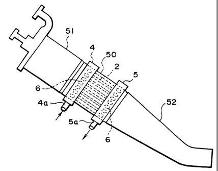
Figure 5 shows a sketch of a gas turbine combustor,
which is a preferred embodiment of this invention.
Figure 6 shows how steam-cooling can be applied in a
combined power plant in which a gas turbine is combined with
a steam turbine.
Description of Preferred Embodiments
In this section a detailed explanation of several
preferred embodiments of this invention will be given with
reference to the drawings. To the extent that the
dimensions, materials, shape and relative position of the
components described in this embodiment are not definitely
fixed, the scope of the invention is not limited to those
specified, which are meant to serve merely as illustrative
examples.
In a gas turbine plant, several combustors of the sort
described earlier, with a combustion nozzle 51 on the gas
inlet side of combustion chamber 50, as shown in Figure 5,
and a tailpipe 52 on the gas outlet side, are provided inside
a cylindrical casing (not shown). The casing is pressurized
using compressed air from a compressor. These combustors are
arranged around the circumference of the casing. The
combustion gases generated in chamber 50 are conducted to the
turbine via tailpipe 52 and used to drive the turbine.
As can be seen in Figure 5, the combustor, which is a
preferred embodiment of this invention, has on the peripheral
surface of the combustion chamber 50 an annular supply
CA 02252077 1998-10-08
manifold 4 on the gas outlet or inlet side of the chamber.
The manifold has a peripheral wall panel whose cross section
is either semicircular or rectangular. There is a recovery
manifold 5 of the same design on the peripheral surface of
the combustion chamber 50, and it is on the gas inlet or
outlet side of the chamber. In Figure 6, the steam generated
by waste heat recovery boiler 45 is used as the energy that
drives steam turbine 46. On the other hand, the steam
extracted by said boiler 45 is then conducted via pipes 4a to
supply manifolds 4. Recovery manifold 5 recovers the steam
after it passes through cooling channels 2 and cools
combustion chamber 50 and transports the recovered steam via
recovery pipe 5a to the inlet of steam turbine 46.
It is not always necessary to provide one supply
manifold for each recovery manifold. There can be a
plurality of pairs of supply and recovery manifolds, or one
supply or recovery manifold can be associated with a
plurality of recovery or supply manifolds, respectively, each
of which is connected by the cooling channels depending on
the combustor scale.
A detailed explanation of the configuration of the
cooling wall panels between the supply manifold 4 and
recovery manifold 5, will next be given with reference to
Figures 1 through 4. In exterior wall panel 1 of the wall of
the combustor, a number of channels 2 for the cooling steam
are laid out parallel to each other on the inner surface ( the
undersurface) of the wall panel. A separate thin heat-
resistant plate 3 is soldered to the undersurface across
which these channels extend. The combustion gases,
represented by the white arrow, flow under plate 3.
CA 02252077 1998-10-08
_g_
Numerous through holes 6 are provided on the surface of
exterior wall panel 1 around the circumference of the
chamber. These holes are in the locations where supply
manifold 4 and recovery manifold 5 are mounted at both ends
of channels 2. The holes 6 may be staggered to the left
and right in a zigzag pattern as shown in Figure 4, or they
may be arranged in a row as is shown in Figure 3.
A detail view of the supply manifold 4 is shown in
Figure 4. Supply manifold 4 is formed by attaching a
channel-shaped piece to wall panel 1 in the location that
faces the through holes 6. The steam for cooling the chamber
is supplied via pipe 4a, which feeds into the channels in the
appropriate place, from a source such as recovery boiler 45
inparallel with gas turbine 43. This steam passes through
hole 6 in the exterior wall panel 1 and is supplied to the
channels 2, which are between wall panel 1 and plate 3, as
shown by the solid arrows in Figure 4.
A detailed description of recovery manifold 5, which is
configured identically to the supply manifold 4, will not be
given.
Preferably exterior wall panel 1 and plate 3, which
constitute the steam-cooled wall, can be composed of
Hastelloy X and Tomilloy (both are registered trademarks).
Exterior wall panel 1 can be 3.0 to 5.0 mm thick, and plate
3, which is soldered to the wall panel, should be 0.8 to 1.6
mm thick.
In this embodiment, then, the combustor wall comprises
two panels ( exterior wall panel 1 and plate 3 ) which have
sealed channels 2 running between them. These channels 2
connect manifold 4, which supplies the cooling steam, and
CA 02252077 2005-11-10
9
recovery manifold 5. As the steam supplied via manifold 4
travels through channels 2 in exterior wall panel 1, it cools
the wall panel. The steam is then recovered through manifold
5.
According to the embodiments, all cooling-steam supplied
is recovered, and no cooling-steam leaks from the system,
which is a necessary feature in the steam-cooling system. This
requirement is achieved in the configuration described above.
This improves the capacity of the gas turbine 43 and reduces
its emission of NOX.
Tn the preceding, the present invention has been
discussed using a preferred embodiment; however, the invention
is not limited to this embodiment only. It should not be
necessary to state that various modifications may be made to
the actual configuration as long as it remains within the
scope of the claims.
EFFECTS OF THE INVENTION
According to this invention, the combustor wall is
actually made of metal panels. It is, therefore, easy to
manufacture the wall by press works for any kind of complex
forms.
In addition to this advantage, the greater heat
resistance of the turbine allows the use of steam as a
pressurized cooling medium. All the requirements for a steam-
cooling system are achieved in this invention, and it
CA 02252077 1998-10-08
-10-
improves the capacity of the gas turbine and reduces its
emission of NOx, thereby contributing to increased efficiency
of the plant as a whole.