Note: Descriptions are shown in the official language in which they were submitted.
CA 02252089 1998-10-16
WO 97139506 PCTlUS97/05957
UNDERGROUND WELL ELECTRICAL CABLE
TRANSITION. SEAL AND METHOD
The present invention relates to an electrical cable transition, seal and
method for an
underground well and, more particularly, to a simplified, low cost transition
, seal and
method for such a cable with a seal that blocks fluid flow to and from the
well and
eliminates any cable splices in the well, and meets the requirements for
electrical codes
and OSHA regulations.
In underground wells such as oil wells, electrical power is furnished to
submersible
pumps and other downhole equipment through insulated electrical conductors
that extend
through conduit in the well casing. In order to connect the downhole equipment
to a
power source outside the well, , these conductors must penetrate a wellhead
barrier that
is sealed to a top opening of the casing. The configuration of cables and
seals in the
wellhead is called a "penetrator," the purpose for which is to provide a
transition zone
where the cable penetrates the wellhead barrier, and gas and other fluids are
prevented
from leaking both into and out of the well.
Because the downhole equipment must be connected to an above-ground power
source, a splice or other connection must be formed between cable connected to
the power
source and cable extending from the downhole equipment. This splice has been
formed
below the wellhead barrier in the past, which isolates the splice from the
area around the
outside of the wellhead barrier which is classified as a hazardous location.
Such hazardous locations are referred to as being "classified" because they
are defined
or classified by industry standards such those promulgated by the American
Petroleum
Institute. The equipment and facilities for such classified locations must be
in compliance
with the Occupational Safety and Health Act ("OSHA") Section 1910, Subpart S,
for
locations where hazardous concentrations of gases or vapors are present
because of
leakage.
A penetrator which has gained acceptance in the oil industry is shown and
described
in U.S. patent 5,829,882, which has the same inventor as the inventions
described below.
This penetrator solved the problem of providing a sealed arrangement for
supplying
electrical power to a sealed wellhead over a petroleum producing well bore in
an area
classified as hazardous, where explosions or fires may occur due to gases and
other
CA 02252089 1998-10-16
WO 97/39506 PCT/US97/05957
-2-
substances associated with the production of petroleum products being ignited
by electric
arcs. The penetrator in U.S. patent 5,289,882, included a rigid conduit with a
splice fitting
formed below the wellhead barrier, for connecting the downhole electrical
conductors of
a wellbore power cable with electrical conductors extending from a power
source on the
surface. A rigid conduit was provided for containing the conductors in the
well, as they
extended from the splice fitting to a rigid conduit outside the wellhead
barrier which had
a breather vent to inhibit the passage of fluids from the downhole electrical
conductor to
the power source electrical conductor. An arrangement was also provided for
securing the
power source electrical conductor adjacent a wellhead to supply power to the
downhole
electrical conductor by extending into the sealed barrier associated with the
welihead and
inhibiting explosions and fires in a hazardous area.
Improvements over the penetrator in U.S. patent 5,829,882, are described in
PCT
application WO 94/25726, and related, pending U.S. patent applications, which
is a
continuation-in-part of U.S. patent 5,829,882.
While these types of penetrators have proven to be safe and effective, they
require a
relatively large number of parts and, since the splice between the electrical
conductors for
the downhole equipment and the power source is located below the wellhead
barrier, they
require a substantial amount of time to complete.
Therefore, there exists a need for providing a lower-cost penetrator that is
easy to
assemble, which reduces the installation time and the cost of the presently-
existing
penetrator, but which does not compromise the safety of the well.
The problems discussed above are solved by the invention described below which
is
directed to a transition for electrical well cable through the wellhead
barrier of an
underground well leading to an electrical power cable connected to an above-
ground
electrical power source, a confined seal for the transition, and a method for
forming the
transition.
The transition includes a length of electrical well cable extending
uninterrupted from
an underground well through the wellhead barrier, a connection between the
underground
well cable and the electrical power cable, the connection being formed outside
the
wellhead barrier within an area adjacent to the wellhead barrier classified as
a hazardous
location. The connection is listed and approved for hazardous locations by a
nationally
CA 02252089 1998-10-16
WO 97139506 PCT/US97/05957
-3-
recognized testing laboratory such as, for example, Factory Mutual Research
Corporation.
A confined seal is located in the well around the electrical well cable for
blocking the flow
of fluid into or out of the well.
The invention applies to electrical well cable which has an outer protective
cable
coating and a plurality of insulated electrical conductors projecting from the
protective
cable coating. A typical electrical well cable includes three electrical
conductors, but the
invention can be applied to other types of electrical well cable in various
shapes, sizes and
configurations.
The transition includes a primary conduit with an inner surface defining an
elongated
opening, the primary conduit extending through at least a portion of the
wellhead barner
and surrounding a portion of the electrical conductors and a portion of the
protective cable
coating. An elastomeric seal is provided in the primary conduit for sealing
the space
between the electrical conductors and the inner surface of the conduit. The
elastomeric
seal has opposed faces, and a relatively hard backing material is located in
the primary
conduit abutting against both faces of the elastomeric seal. The relatively
hard backing
material is located around and between the conductors in the inner surface of
the conduit.
The backing material can also surround at least a part of the protective cable
coating that
extends into the elongated opening of the primary conduit.
The transition also includes an elongated rigid conduit extending between the
primary
conduit and an opening in the wellhead barrier for each of the conductors. A
fluid-tight
connection is formed between one end of the elongated conduits and the primary
conduit
and also between the other end of the elongated conduits and the wellhead
barrier
openings.
One of the fluid-tight connections includes a manifold cap connected to the
primary
conduit, with openings in the manifold cap for receiving the elongated rigid
conduits. A
back-up bushing is positioned between the relatively hard backing material and
the
manifold cap. The backing material preferably formed of an epoxy putty with
good
dielectric properties that is resistant to well fluids and which is compressed
before it
hardens to surround the conductors and fill the spaces in the elongated
opening in the
primary conduit. The elastomeric seal is preferably formed of synthetic
rubber.
A method for forming the confined elastomeric seal begins with exposing at
least one
CA 02252089 2004-11-09
-4-
insulated electrical conductor by removing the outer protective coating from a
portion
of electrical well cable that extends uninterrupted from downhole electrical
equipment. A relatively hard backing material, such as the epoxy putty
mentioned
above, is positioned around the insulated conductor cable and abutting
opposing faces
of the elastomeric seal. The backing material extends along the insulated
electrical
conductor on both sides of the seal.
The seal and relatively hard backing material are surrounded along the length
of the insulated electrical conductor with a primary conduit for isolating the
insulated
electrical conductor from the well and forming a seal around the conductor.
The seal
is then confined between the portions of hardened backing material to prevent
well
fluids from flowing both into and out of the well between the insulated
electrical
conductor and the primary conduit.
The elastomeric seal is preferably formed with an outer diameter larger than
the opining of the primary conduit, and with openings for receiving the
insulated
electrical conductors, are smaller than the outer diameter of the conductors
for
providing a tight seal between adjacent surfaces. The seal is confined by
compressing
the epoxy putty before it hardens to fill all the spaces in the primary
conduit and
around the elastomeric seal, insulated electrical conductor and electrical
well cable. A
compressing tool connected between the primary conduit and the electrical well
cable
can be used to compress the epoxy putty and extrude it before it hardens into
all of the
spaces in the primary conduit.
A transition for insulated electrical well cable adapted for passage through a
wellhead barrier of an underground well leading to an electrical power cable
connected to an above-ground electrical power source, the transition
comprising:
(a) a length of insulated electrical well cable extending uninterrupted from
an
underground well through the wellhead barrier; (b) connection between the
insulated electrical well cable and the electrical power cable, the connection
being
formed outside the wellhead barrier within an area adjacent to the wellhead
barrier
classified as a hazardous location, the connection being listed and approved
for
hazardous locations by a nationally recognized testing laboratory; (c) an
elastomeric
seal in the well around the insulated electrical well cable, the seal being
confined
for blocking the flow of fluid into or out of the well.
CA 02252089 2004-11-09
-4a-
In accordance with another aspect of the present invention there is provided a
confined seal for blocking fluid flow in a transition for electrical well
cable through a
wellhead barrier of an underground well, wherein the electrical well cable has
an
outer protective coating and at least one insulated electrical conductor
projecting from
the protective coating, the seal comprising: (a) a primary conduit having an
inner
surface defining an elongated opening for receiving the insulated electrical
conductor
and at least a portion of the outer protective cable coating; (b) an
elastomeric seal
with opposing faces for providing a seal between the insulated electrical
conductor
and the inner surface of the primary conduit; and (c) relatively hard backing
material
abutting against the opposing faces of the elastomeric seal located around and
between the conductor and the inner surface of the primary conduit for
confining the
elastomeric seal in the primary conduit.
In accordance with yet another aspect of the present invention there is
provided a method of forming a confined elastomeric seal for a transition for
electrical well cable in a wellhead barrier of an underground well, comprising
the
steps o~ (a) exposing at least one insulated electrical conductor by removing
an
outer protective coating from a portion of electrical well cable that extends
uninterrupted from downhole electrical equipment; (b) positioning a relatively
hard
backing material and an elastomeric seal with opposing faces around the
insulated
conductor cable, the relatively hard backing material abutting both opposing
faces of
the elastomeric seal, and extending along the insulated electrical conductor
on both
sides of the seal; (c) surrounding the seal and relatively hard backing
material along
the length of the insulated electrical conductor with a primary conduit for
isolating the
insulated electrical conductor from the well and forming a seal around the
conductor;
and (d) confining the seal between the hardened backing material to prevent
well
fluids from flowing both into and out of the well between the insulated
electrical
conductors and primary conduit.
A better understanding of the present invention can be obtained when the
following detailed description of exemplary embodiments is considered in
conjunction with the following drawings, in which:
CA 02252089 2004-11-09
-4b-
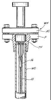
FIGURE 1 is a front elevational view, partially in section, of the wellhead
barrier of an underground well with an electrical penetrator utilizing the
present
invention;
FIGURE 2 is a side elevational view, partially in section, of the wellhead
barrier and electrical penetrator system of Fig. l, which in addition shows a
splice
fitting outside the wellhead barrier;
FIGURES 3 and 4 are partial sectional views of the penetrator of Figs. 1
and 2, showing in particular details of the seal for blocking the flow of
fluid from
around insulated electrical conductors;
CA 02252089 1998-10-16
WO 97/39506 PCT/US97/05957
-S_
FIGURE 5 is a perspective view of the primary rigid conduit that encases the
seal in
Figs. 3 and 4, and the elongated conduits that extend from the primary conduit
to the
wellhead barrier;
FIGURE 6 is a perspective view of an elastomeric seal that seals the insulated
electrical conductors in the primary conduit;
FIGURE 7 is a sectional view looking along line 7-7 of Fig. 4;
FIGURE 8 is a sectional view looking along line 8-8 of Fig. 4;
FIGURES 9-13 are front elevational views, partially in section, that
illustrate a
method of forming the transition seal shown in Figs. 3 and 4;
FIGURE 14 is a front elevational view, partially in section, which shows the
invention used in another type of wellhead barrier;
FIGURE 15 is a front elevational view, partially in section, which shows the
present
invention used in a wellhead with a single penetrator tube;
FIGURE 16 is a sectional view of the penetrator of Fig. 15;
FIGURE 17 is a front view, partially in section, which shows the invention
used with
another type of single penetrator tube; and
FIGURE 18 is a sectional view of the penetrator of Fig. 17.
The subject invention relates to a penetrator for electrical conductor cable
which
transmits electrical power from an above-ground remote electrical power source
(not
shown) to downhole electrical equipment such as submersible pumps. Penetrators
which
have previously been sold, such as the one shown and described in U.S. patent
5,289,882
and PCT application WO 94/25726, involve the formation of a splice in or below
the
wellhead barrier, between the conductor cable connected to the downhole
equipment and
the conductor cable connected to the remote power source.
The invention described in detail belaw is directed to a different type of
transition or
penetrator for electrical conductor cable which eliminates the splice between
the cable
connected to the downhole equipment and the power source conductor cable. In
other
words, any break or interruption in the electrical cable from the downhole
equipment is
eliminated as it extends through in the well. The invention also includes a
unique, self
energized, confined seal in the well around the cable, which effectively
blocks fluid from
flowing either into or out of the well, and a method of forming such a seal
and transition.
CA 02252089 1998-10-16
WO 97/39506 PCT/US97/05957
-6-
By providing for this type of transition, cost is significantly lowered by
reducing the
number of parts required and the installation time, without compromising well
safety.
Figs. l and 2 are front and side views, respectively, of a wellhead barrier WH
of an
underground well, which includes the transition formed in accordance with the
invention.
In the described embodiment, a remote power source furnishes conventional
three-phase
power through conductor cable with three conductors. However, other types and
sizes of
conductor cable can be used in accordance with the invention.
As best shown in Fig. 2, power from the remote power source is transmitted to
the
well through an electrical conductor cable 2, which is connected to the remote
power
source (not shown). The conductor cable 2 has an outer protective coating 4
known as an
armored cladding, which is typically covered by an impervious polymer sheath,
that is
well known in the industry. The conductor cable 2 also includes three
insulated
conductors 6a, 6b and 6c, that carry the three-phase power, and one
uninsulated ground
conductor 6d.
The remote power source is located in a safe zone, which is a zone outside a
hazardous location adjacent to the well which might contain gases and other
fluids
originating from the well. The term "hazardous location" as used herein is
that area
around a wellhead barrier that is classified as hazardous under industry
standards as
described above.
The conductors 6a, 6b and 6c extend through an electrical cable seal
termination 7,
which connects to a conduit seal fitting 8 which is used as a Tee for a
breather drain or
vent 8a. The Tee 8 is in turn connected to a conduit outlet body or housing 66
which
houses an electrical splice generally designated by reference letter S, all of
which are
located outside the wellhead barrier WH.
The splice S is described in greater detail below and is used to connect the
conductor
cable 2 to a conductor cable 10 that is connected to and extends from downhole
electrical
equipment (not shown). The splice S is also described in detail in U.S. patent
5,289,882,
and PCT application WO 94/25726, and has been approved by Factory Mutual
Research
Corporation, which is a nationally recognized testing laboratory, for
locations classified
as hazardous. However, unlike the invention in U.S. patent 5,289,992 and PCT
application WO 94/25726, the splice S, which is located outside the wellhead
barrier WH,
CA 02252089 1998-10-16
WO 97/39506 PCT/US97/05957
is the only connection between the conductor cable 2 from the power source and
the
conductor cable 10.
In order to provide an effective electrical transition from the wellhead
barrier WH to
the external power source, without a splice or other electrical connection in
or below the
wellhead barrier WH, an effective seal must be used in order to prevent gases
and other
fluids from being transmitted from the well through the wellhead barrier WH to
the
outside, through or around the electrical conductor cable 10 from downhole
equipment.
For example, when a downhole pump (nat shown) is turned off, pressure inside
the well
casing can typically range between SO - 3,000 psi. This exerts a high pressure
along the
electrical conductor cable 10 which, if an effective seal is not provided,
could cause gas
and other liquids to leak out of the wellhead barrier WH. Also, when the
downhole pump
is turned on or the casing is vented, pressure inside the casing rapidly
decreases. This
causes gases and other fluids entrained in and around seals, cable insulation
and the cable
jacket to expand, which could cause the seals to fail and blow out of the
primary conduit
16. The transition described below includes a confined seal which effectively
blocks the
flow of fluid in both directions under the conditions described. The seal,
which is
described in greater detail below, is part of the penetration system of the
invention.
As shown in Figs. 3 and 4, the conductor cable 10 contains three insulated
conductors
12a, 12b and 12c. Like the conductor cable 2, the conductor cable 10 is
armored, which
means it has an outer protective coating 14. The spaces between the conductors
12a, 12b
and 12c and the protective coating 14 are filled with a dielectric cable
insulation (not
shown) that is well known and encapsulates the conductors.
The conductor cable 10 extends into a rigid primary conduit 16, in which the
confined
two-way seal is formed. As best shown in Fig. 2, the conductor cable 10 and
the primary
conduit 16 are secured to a length of production tubing PT through a plurality
of cable
bands 18. As shown, five cable bands 18 can be used to hold the conductor
cable 10 to
the production tubing PT, while another, upper cable band secures the primary
rigid
conduit 16 to the production tubing PT.
The seal in the primary conduit 16 is formed, as shown in Fig. 9, by first
trimming the
armor cladding 14 and internal cable insulation (not shown) that encapsulates
the insulated
conductors, to expose the insulated conductors 12a, 12b and 12c, so they can
extend
CA 02252089 1998-10-16
WO 97/39506 PCT/CTS97/05957
-g_
through the wellhead barrier WH and into the area outside of the wellhead WH
classified
as a hazardous location. As shown in Fig. 4, the insulation I is maintained on
each of the
conductors.
As shown in Fig. 9, an epoxy putty, designated generally by reference numeral
22a,
is packed around the conductors 12a, 12b and 12c, and also around the trimmed-
off end
of the armored coating 14, so that the epoxy putty 22a extends a short
distance along the
outer surface of the coating 14.
The epoxy putty is preferably a hand-kneadable, two-part epoxy that hardens in
a
relatively short period of time after it is mixed and packed around the
conductors 12a, 12b
and 12c (for example, from 3-30 minutes). The putty must have a very low
shrinkage
upon hardening and also be resistant to well fluids. It must also have good
dielectric
qualities and be stable at temperatures up to at least 200°F. There are
commercially-
available putties of this type on the market from manufacturers such as
Polymeric
Systems, Inc., Phoenixville Pennsylvania and Glenmarc Manufacturing, Inc.,
Spring
Grove, Illinois.
Referring to Fig. 10, an elastomeric seal 20 (shown in detail in Fig. 6) with
openings
20a, 20b and 20c, is positioned on the conductors 12a, 12b and 12c, above the
epoxy putty
22a that was packed as described above. The seal is preferably formed of a
synthetic
rubber, but can be formed of any elastomeric material with dielectric
properties, that is
resilient and resistant to well fluids. The seal 20 has an outer diameter that
is slightly
larger than the inside diameter of the primary conduit 16 to form an
interference fit and
an initial seal.
After the seal 20 is positioned as shown in Fig. 10, a second amount of epoxy
putty
22b is packed above the seal 20 and around the conductors 12a, 12b and 12c as
shown in
Fig. 11.
As shown in Fig. 12, after the epoxy putty 22a and 22b is packed as shown in
Fig. 11,
a back-up bushing 24 is positioned on the conductors 12a, 12b and 12c into
engagement
with the upper end of the epoxy putty 22b. The back-up bushing 24 is formed of
a non-
ferromagnetic material such as brass, and is shown best in Figs. 4 and 12, and
sectional
view 7. After the elastomeric seal 20 and back-up bushing 24 are positioned as
shown and
the epoxy putty 22 is packed as shown in Fig. 12, the primary conduit 16 is
installed as
CA 02252089 1998-10-16
WO 97139506 PCT/LTS97105957
-9-
shown in Fig. 13. During this installation process, the epoxy putty has not
yet hardened
and is still formable.
As shown best in Figs. 4 and 5, a manifold cap 26 is mounted on the primary
conduit
16, over the conductors 12a, 12b and 12c. Three rigid, elongated conduits 28a,
28b and
28c, one for each of the conductors 12a, 12b and 12c, extend from the primary
conduit 16
to openings in a flange F in the wellhead. The primary conduit 16, manifold
cap 26 and
elongated conduits 28a, 28b and 28c are formed as a single unit of a non-
ferromagnetic
metal such as stainless steel, with fluid-tight connections between them.
These
connections are accomplished through soldering or other suitable connections.
As shown best in Fig. 4, the manifold cap 26 has an outer ledge 30 which
engages the
upper end of the primary conduit 16, and inner ledges 32 for receiving the
lower ends of
the elongated rigid conduits 28a, 28b and 28c. As also shown in Fig. 4, the
conductors
12a, 12b and 12c extend through the rigid conduits 28a, 28b and 28c, the
latter serving to
isolate the conductors from the well fluids.
Referring to Fig. 13, after the primary conduit 16 is positioned over the
conductors
12a, 12b and 12c and the back-up bushing 24, putty sections 22a and 22b, seal
20, and a
portion of the cable 10, to where a lower edge 31 of the manifold cap 26
engages the
back-up bushing 24, a compression tool generally designated by reference
numeral 34 is
mounted as shown in Fig. 13. A pair of lower sleeved sections 36 are mounted
onto the
armored cladding 14 of the conductor cable 10 and clamped in place as shown
generally
by clamps 38. At this position, a pair of upper sleeves 40, are mounted over
the elongated
conduits 28a, 28b and 28c. The upper sleeves 40 have an inner opening that is
large
enough to surround the elongated rigid tubes 28a, 28b and 28c, but small
enough to
engage the upper surface of the manifold cap 26. A pair of arms 42, pivotally
connected
to the lower sleeves 36, operate to pull the primary conduit 16 downwardly in
the
direction of arrow 44 to the position shown in Fig. 13, through a pair of
links 45, when the
arnis 42 are moved in the direction of the arrows 46.
This downward movement of the manifold cap 26 against the back-up bushing 24
compresses the still-formable epoxy putty 22 so that it completely fills the
inner
passageway of the rigid conduit 16. The primary conduit 16 has a series of saw
tooth
shaped grooves 48 located on its inner surface or other means for holding the
primary
CA 02252089 1998-10-16
WO 97/39506 PCT/US97/05957
-10-
conduit 16 firmly in place when the epoxy putty 22a and 22b hardens and to
hold the cable
firmly in conduit 16 under pressure.
The seal formed by this arrangement of parts has been found to be effective in
blocking the flow of fluids at high well pressures. As shown in Fig 6, the
elastomeric seal
5 20 can be formed with a beveled lower surface 50 and sleeves 52 which extend
along the
conductors 12a, 12b and 12c for providing better contact between the
elastomeric seal 20
and the inner wall of the primary conduit I6 and with the insulation I on the
outer surface
of the conductors 12a, 12b and 12c.
The elastomeric seal 20 is self energized because it is slightly larger in
diameter than
10 the elongated opening in the primary conduit 16 and the openings 20a, 20b
and 20c are
slightly smaller than the insulated conductors I2a, 12b and 12c for providing
an
interference fit with them. When the primary conduit 16 is installed and the
ledge 31 of
the manifold cap 26 pushes against the back-up bushing 24, the epoxy putty 22a
and 22b
is compressed and extruded in and around all the small spaces associated with
the conduit
10, the insulation jacket inside the conduit 10, the seal 20, the insulation I
on the
conductors 12a, I2b and 12c, and the back-up bushing 24. When the epoxy putty
22a and
22b hardens to a relatively hard mass, it confines the seal 20 as well as the
conductor
insulation I and the internal insulation jacket (not shown) in the cable 10.
This confining
action, in addition to providing an effective seal when the well is pressured,
also prevents
gas and other fluids entrained in the elastomeric seal 20 and other resilient
materials such
as the insulation I from expanding out of the primary conduit 16 and off of
the insulated
conductors. This condition could occur when pressure is released from the well
causing
fluid entrained under pressure in the seal 20, insulation I, and the
insulation jacket in the
well cable 10, to expand and rupture the seal and insulations, causing leakage
and
electrical short circuits. Thus, the confined seal is self energized and
operates as a two-
way seal.
As mentioned above, the rigid, elongated tubes 28a, 28b and 28c serve as
conduits
for the conductors 12a, 12b and 12c and isolate them from the annulus of the
well casing.
This is done, as shown in Fig. 2, through the fluid-tight connection between
the rigid tubes
28a, 28b and 28c and the manifold cap 26 (Fig. 4), as well as a rigid
connection between
the tubes 28a, 28b a.nd 28c and the flange F of the wellhead WH. This
connection is a
CA 02252089 2004-11-09
-11-
conventional ferrule-type fitting, generally designated by reference numeral
54, for
connecting the rigid tubes 28 to cooperating rigid tubes 56 that extend
through the
flange F and adapter spool AS. Another ferrule-type fitting 58, described in
detail in
PCT application WO 94/25726, connects the tubes 56 to a like number of
flexible
housings 60 that extend through fittings 62 to a fitting 64 that couples a
splice
housing 66 to the Tee 8 and cable seal termination 7.
The electrical conductors 6a, 6b and 6c extend through an internal seal (not
shown) of the cable seal termination 7 in order to block the flow of gas and
other
fluids, internal flames and explosions originating within the well from
spreading into
the armored conductor cable 2. The Tee 8 includes a breather tube 8a for
venting
gases and other fluids from the well in the event of a failure of the primary
seal 20.
The Tee 8 forms a pathway for the conductors 6a, 6b and 6c. The housing 66
protects splices or other connections between the conductors 6a, 6b and 6c
which are
connected to the external power source, and the conductors 12a, 12b and 12c
connected to the downhole equipment.
Because it is possible for the insulation I of the conductors 12a, 12b and 12c
to
serve as conduits for gas and other fluids originating from the well, the
insulated ends
of the conductors 12 are inserted into vented rubber seals 68 described in PCT
application WO 94/25726, before the uninsulated ends of the conductors 12a,
12b and
12c are electrically connected to the conductors 6a, 6b and 6c. The splice
connections S will not be described in detail since they are shown and
described in
U.S. Patent No. 5,289,882, and in PCT application WO 94/25726. While the
invention is described in terms of providing a splice fitting outside the
wellhead
barrier WH between conductors connected to the downhole equipment and
conductors
connected to the power source, the invention contemplates other types of
connections
between these respective conductors outside of the wellhead barrier.
Figs. 14-18 illustrate alternative applications for the penetrator described
above. In Fig. 14, the same internal seal discussed above for conductor cable
110 is
contained in a rigid primary conduit 116. Rigid elongated tubes 128a, 128b and
128c
extend from the primary conduit 116 for encasing the conductors in the same
manner
shown in Figs. 1-3.
CA 02252089 1998-10-16
WO 97/39506 PCT/US97/05957
-12-
However, in this embodiment, the tubing hanger TH forms the wellhead barrier
WH for
the well that must be penetrated by the conductors (not shown in detail). The
tubing
hanger TH is supported in the well casing WC and secured in place by bolts
120, which
are threaded through well bore casing flange 122 such that they contact the
tubing hanger
TH. Thus, in this application an upper adapter flange of the type shown in
Figs. 1-3 is not
used in forming the wellhead WH.
Figs. 15-16 illustrate another application for the penetrator described above,
which
also has an internal confined seal contained in the same type of rigid primary
conduit 216.
However, this application is different because only a single, elongated
conduit or
penetrator tube 228 extends through a passageway in the wellhead barrier WH.
The
wellhead barrier WH includes split upper and lower back up plates 230, 232 for
holding
a split elastomeric seal 234, for sealing the exterior of the penetrator tube
228 to the
wellhead barrier WH. A split holding flange 236 is bolted to a lower wellhead
flange 238
for clamping the back up plates 230, 232 and the seal 234. As shown in Fig.
15, the
tubing hanger TH is of the slip-type where production tubing PT is held by
teeth on the
tubing hanger, as is known in the art.
Insulated conductors 212a, 212b and 212c extend through the penetrator tube
228.
A manifold cap 226 is secured to the penetrator tube 228 by soldering or other
acceptable
methods. A conventional fitting 240 is used to connect a portion of the
penetrator tube
228 that extends out of the wellhead barrier WH to other conduit that leads to
the splice
or other connection (not shown) with the electrical conductor cable connected
to the
power source.
Figs. 17 and 18 illustrate another application for the penetrator where the
seal is
formed in the same manner as described above. In this application, a rigid
primary tube
316 is mounted to the lower end of a mandrel tube 328. A manifold cap 326 is
secured
to the primary tube 316 by soldering or the like and abuts an internal
shoulder 340 formed
in the mandrel tube 328. The conductors 312a, 312b and 312c extend through the
mandrel
tube 328, which extends through the wellhead WH in a known way. A pair of
elastomeric
O-rings 342 seal the space between the primary conduit 316 and the inner
surface of the
mandrel tube 328.
By providing a penetrator system of the type described above, the primary
insulation
CA 02252089 1998-10-16
WO 97/39506 PCT/US97/05957
-13-
for conductor cable connected to underground equipment is not interrupted
until it is
spliced to conductor cable connected to the power source outside of the
wellhead. The
splice is formed in an approved connection , which satisfies OSHA requirements
for
hazardous locations, and is approved by a nationally recognized testing
laboratory such
as Factory Mutual Research Corporation. The splice is formed in a manner that
is listed
and approved for classified hazardous locations which are adjacent to the
wellhead.
The invention provides a transition which is much less expensive than ones
previously used, which can easily be fabricated in the field when installing
an electric
submersible pump in a well. The transition can be formed on a conventional
electrical
pump cable of different sizes and types without the need for any special
adaptations, in
certain applications it avoids typical space requirements in the wellhead
barrier where an
electrical splice or other connection is formed in or below the wellhead
barrier, it avoids
breaking the insulation of the conductors which extend from the downhole
equipment, and
eliminates a number of parts. Also, a great deal of time is saved during
installation in the
field by eliminating the need for a downhole cable splice.
The foregoing disclosure and description are intended to be illustrative and
explanatory of the invention, thereof, and various changes in the size, shape
and materials,
as well as the details of the illustrated operation and construction may be
made without
departing from the spirit and scope of the invention.