Note: Descriptions are shown in the official language in which they were submitted.
CA 02252179 2001-12-04
STEERING CONTROL SYSTEM FOR TRACKED VEHICLE
Background of the Invention
The invention relates to a steering control system for a tracked vehicle.
Tracked vehicles are steered by driving one track faster or slower than the
other. Most
tracked vehicles with differential steering have a steering pump which is
driven by the
engine rather than by the ground, so that the vehicle can turned without
forward or reverse
translational vehicle motion, and so that a more reasonably sized pump can be
used. On
currently available tracked vehicles, such as the 8000T tractor manufactured
by John Deere
and on tracked vehicles manufactured by Caterpillar, the steering wheel is
spring centered
so that there will be no vehicle turning unless the operator intentionally
commands the
vehicle to turn by rotating the steering wheel away from its spring-centered
position. Such a
system is described in US Patent No. 5,948,029, issued 7 Sept. 1999 to
Straetker, and
assigned to the assignee of this application.
A non-spring-centered steering input device is described in pending US Patent
No.
6,000,490, and assigned to the assignee of this application. This non-centered
steering
input device makes possible a steering function which performs similar to the
steering
function of a wheeled vehicle. A primary characteristic of a wheeled vehicle
steering
function is that rotation of the steering wheel commands a particular
curvature of the
vehicle's path, and the amount of curvature is largely independent of the
engine speed,
wheel speed, vehicle weight, or ground conditions. This characteristic is
achieved for a
tracked vehicle by sensing wheel speed and steering motor speed and
controlling the
relative speed of the tracks in proportion to the wheel speed. If the vehicle
is moving
quickly, the tracks have a large relative motion, and this relative motion is
reduced as the
vehicle slows down. When the vehicle stops forward or reverse longitudinal
motion, track
relative motion also stops.
However, with such a steering input device, when the vehicle is performing a
sharp turn and
the transmission is disengaged, either by depressing the clutch or shifting to
neutral, it is
possible for tractor momentum to continue vehicle motion, or the steering
motor may
actually propel the vehicle through this sharp turn. The control system will
sense the
longitudinal motion of the vehicle and command the proper track relative
motion to maintain
the turn radius. However, when the track relative motion is the actual cause
of the
longitudinal motion, then it is possible for the vehicle to inadvertently
continue turning until
the operator intervenes - a self-perpetuating turn. It would be desirable to
provide a
steering control system which prevents or limits self-perpetuating turns.
CA 02252179 2001-12-04
Summary of the Invention
Accordingly, an object of this invention is to provide, for a tracked vehicle
steering
system with a non-spring-centered steering input device, a steering control
system which
does not permit or which limits self-perpetuating turns.
These and other objects are achieved by the present invention, wherein a
tracked
vehicle includes a differential steer system utilizing one variable
displacement pump and one
fixed displacement motor with an electro-mechanical steering linkage and a non-
spring
centered steering wheel. A steering control system senses steering wheel
position, vehicle
speed, engine speed, steering motor speed, whether or not the transmission is
in gear or in
neutral, and whether the clutch is engaged or disengaged. An algorithm
operates to
gradually and repeatedly decrease the commanded steering motor speed if the
transmission
is in neutral or the clutch is not engaged, and the steering motor speed
divided by the wheel
speed is greater than a threshold, and the wheel speed is less than a certain
fraction of the
engine speed. Alternatively, an algorithm prevents increases in steering motor
speed if a
ratio of the steering motor speed to the vehicle speed is greater than a
threshold,
Brief Description of the Drawings
Fig. 1 is a simplified schematic diagram of a tracked vehicle drive and the
control
system of the present invention; and
Fig. 2 is a logic flow diagram of an algorithm executed by the control system
of FIG.
1.
Fig. 3 is a logic flow diagram of an algorithm for an alternative embodiment
of the
invention.
Detailed Description
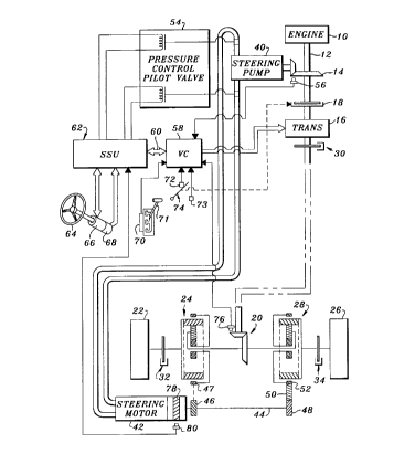
Referring to Fig. 1, a drive train of a tracked vehicle includes an engine 10
with an
output shaft 12 which drives a right angle gear 14 and a transmission 16. The
transmission
16 drives a clutch 18 which, in turn, drives, via right angle drive 20, a left
track drive wheel
22 via left steering planetary drive 24, and a right track drive wheel 26 via
right steering
planetary drive 28. The steering planetary drives 24 and 28 are preferably
such as
described in US Patent No. 5,390,751, issued 21 Feb. 1995 to Puetz et al., and
assigned to
the assignee of this application. Additional outboard planetaries (not shown),
as provided
on John Deere 8000T tractors, are mounted between the steering planetaries and
the
respective drive wheels, but are not further described because they are not
involved in the
2
CA 02252179 2001-12-04
steering control function which is the subject matter of this application. A
parking brake 30
is coupled to the transmission output shaft, and left and right service brakes
32, 34 are
coupled to the left and right drive wheels 22, 26, respectively.
The right angle gear 14 drives a variable displacement steering pump 40, such
as a
75 cc, 90 series pump made by Sauer-Sundstrand. The pump 40, in turn, powers a
hydraulic fixed displacement steering motor 42, such as a 75 cc, 90 series
motor, also made
by Sauer-Sundstrand. The steering motor 42 drives, via a cross shaft 44 and
gear 46, a
ring gear 47 of left planetary drive 24, and via cross shaft 44, gear 48 and
reverser gear 50,
a ring gear 52 of right planetary drive 24.
The swashplate (not shown) of steering pump 40 is controlled by a pressure
controlled pilot valve or electronic displacement control (EDC) 54. The EDC is
preferably a
known two stage device with first stage including a flapper type valve and a
second stage
including a boost stage to the pump, such as is used on the commercially
available John
Deere 8000T tracked tractor.
A rotation speed sensor 56, such as a commercially available magnetic pickup,
mounted in proximity to the right angle drive 14, provides an engine speed
signal to a
vehicle controller VC 58, such as is used on the commercially available John
Deere 8000T
tracked tractor. The vehicle controller 58 controls the transmission 16 and
other vehicle
functions, and is connected via a bus 60 to a steering controller or steering
system unit
(SSU) 62. The solenoids of EDC 54 are controlled by pump command signals
generated by
SSU 62.
An operator controlled steering wheel 64 is preferably not spring centered, is
capable
of turning through an unlimited angular range, and is coupled to a variable
friction feel
steering input device 66, such as described in the aforementioned US Patent
No. 6,000,490
which is hereby incorporated by reference. The steering input device 66
preferably includes
a transducer unit 68 which generates signals representing the changes in
position of the
steering wheel 64 for communication to the SSU 62. The transducer unit 68
preferably
includes a pair of gear-driven rotary incremental encoders(not shown), such as
a
commercially available OakGrigsby 900 Optical Encoder or a Grayhill Series 61
H encoder.
A transmission shift lever transducer 70, such as described in US patent
5,406,860,
issued 18 Apr. 1995 to Easton et al., provides commanded forward, neutral,
reverse and
commanded gear signals to a powershift transmission control unit (not shown)
which is part
of the vehicle controller VC 58 as a function of the position of a shift lever
71. Clutch
3
CA 02252179 2002-05-16
switches 72 and 73 provide signals to the VC 58 (and to SSU 62 via bus 60)
when the clutch
pedal 74 is fully released and fully depressed, respectively.
A drive line rotation speed sensor 76, preferably a differential Hall-effect
speed
sensor such as used on production John Deere tractors, is mounted in proximity
to the right
angle drive 20, provides to the VC 58 (and to SSU 62 via bus 60) a final drive
speed, vehicle
or wheel speed signal (whl spd). A magnetic ring 78 is mounted for rotation
with the motor
42, and a Hall-effect transducer 80 mounted near the magnetic ring 78 provides
to the SSU
62 a motor speed signal and a motor direction signal.
The SSU 62 includes a commercially available microprocessor (not shown) and
controls the speed of the steering motor 42 as a function of various inputs,
as described in
the aforementioned US Patent No. 5,948,029. Except for the steering input
device 66 and
the algorithm illustrated in Fig. 2, the elements shown in Fig. 1 are similar
to those used on
the commercially available John Deere 8000T tracked tractor.
According to the present invention, once every 20 milliseconds for example,
the SSU
62 executes a main loop control program which calls or executes the algorithm
or subroutine
illustrated by Fig. 2. This subroutine begins at step 100. In step 102 the
algorithm
determines, from information provided from the VC 58 whether or not the
transmission 16 is
in neutral, and from signals provided by the clutch pedal switches 72 and 73,
whether the
clutch 18 is not engaged. If the transmission 16 is not in neutral and the
clutch 18 is
engaged, step 102 directs the algorithm to step 110 which returns control to
the main loop.
On the other hand, if the transmission 16 is in neutral or if the clutch 18 is
not engaged, step
102 directs the algorithm to step 104.
Step 104 calculates a ratio of steering motor speed (from sensor 80) divided
by the
wheel speed (from sensor 76), and compares this ratio to a predetermined
value, such as
10. If the ratio is not greater than 10, the algorithm is directed to exit via
step 110. If the
ratio is greater than 10, the algorithm is directed to step 106.
Step 106 compares the sensed wheel speed to a value equal to a fraction, 0.06
for
example, of the engine speed. (The 0.06 factor used in step 106 depends on how
fast the
steering pump 40 turns relative to the engine speed, and the rotation speed of
steering
motor 42 relative to steering pump 40) If the wheel speed is not less than
0.06 times the
engine speed, the algorithm is again directed to exit via step 110. If the
wheel speed is less
than 0.06 times the engine speed, the algorithm is directed to step 108.
4
CA 02252179 2001-12-04
Alternatively, if no engine speed signal is readily available, step 106' could
be used
instead of step 106. Step 106' compares the sensed wheel speed to a reference
vehicle
speed such as, for example, 6 kilometers per hour (km/h). If the wheel speed
is not less
than 6 km/h, the algorithm would be directed to exit via step 110. If the
wheel speed is less
than 6 km/h, the algorithm would be directed to step 108.
From either step 106 or 106', the algorithm would proceed to step 108 which
multiplies by 0.98, for example, the absolute value of a count value which
causes a small
reduction in the speed of the steering motor 42, thereby reducing the velocity
difference
between the left and right track drive wheels 22 and 26, respectively. This
subroutine is
preferably executed 50 times per second. Thus, if the conditions tested in
steps 102-106
remain true for one second, the count value and the steering motor speed would
be reduced
by almost two thirds.
It was determined that, for a tractor with a 2 meter tread, a self-
perpetuating turn
situation can exist only if the turn radius is well under 2 meters, and that a
self-perpetuating
turn situation can exist only if the conditions set forth in steps 102-106 are
all met. Thus,
when these conditions are all met, step 108 will gradually reduce the speed of
the steering
motor 42. This increases the commanded turn radius and prevents a self-
perpetuating turn
situation.
Referring now to Fig. 3, an alternative embodiment will now be described
wherein
neither a transmission sensor nor a clutch sensor is utilized. This
alternative subroutine
begins at step 200. In step 202 the algorithm calculates a ratio of steering
motor speed
(from sensor 80) divided by the wheel speed (from sensor 76), and compares
this ratio to a
predetermined value, such as 10. If the ratio is not greater than 10, the
algorithm is directed
to exit via step 206. If the ratio is greater than 10, the algorithm is
directed to step 204.
Step 204 prevents increases of the speed of the steering motor 42, thereby
preventing turn
radii less than a certain amount and thereby preventing self-perpetuating turn
situations.
While the present invention has been described in conjunction with a specific
embodiment, it is understood that many alternatives, modifications and
variations will be
apparent to those skilled in the art in light of the foregoing description.
Accordingly, this
invention is intended to embrace all such alternatives, modifications and
variations which fall
within the spirit and scope of the appended claims.
5