Note: Descriptions are shown in the official language in which they were submitted.
CA 022~227~ 1998-11-02
ITW CASE 8215
QUICK THREAD WRAPPING MA~lN~: STRETCH HEAD
AND WRAPPING FILM METHOD
FIELD OF THE INVENTION
The present invention relates generally to stretch
film wrapping machines, and more particularly to a new and
improved wrapping machine stretch head comprising a plurality
of stretch rollers around which the stretch film is able to be
routed or threaded in a ~uick, easy, and safe manner.
BACKGROUND OF THE INVENTION
Film wrapping machines for wrapping products or
articles in wrapping film conventionally comprise a film roll
upon which a supply of the wrapping film is disposed, and a
plurality of rollers around which the wrapping film is routed
so as to have a predetermined amount of tension developed
within the film such that the wrapping film exhibits a prede-
termined or requisite amount of tension required for the film
wrapping operation. One conventional type of film wrapping ma-
chine comprises a set of rollers fixedly mounted within re-
spective upper and lower frame members whereby, for example, a
leading end of the wrapping film must be withdrawn from the
film supply roll and manually routed or threaded through and
around the set of tension rollers. This process or operation,
however, has proven to be very awkward, difficult, and tedious
for operator personnel because the film must be threaded or
routed beneath the upper frame member and between the tension
rollers. Such requirements have additionally manifested them-
selves in rendering the wrapping film threading or routing
process or operation quite time consuming whereby non-product-
. .. __ . . . "
CA 022~227~ 1998-11-02
ive downtime, attendant for example the exchange of wrapping
film supply rolls when a particular wrapping film supply roll
which has been depleted is being removed and a new wrapping
film supply roll which has a fresh supply of wrapping film
thereon is being installed, has been relatively extensive.
In order to improve upon the foregoing conventional
type of film wrapping system such that the film threading or
routing operation is rendered less awkward, difficult, tedi-
ous, and time-consuming, another conventional type of film
wrapping system was developed wherein the threading or routing
of the wrapping film around the various tension rollers was,
in effect, rendered "automatic" due to the presence or rela-
tive disposition of, for example, a plurality of fixed film
tension rolls and a plurality of relatively movable press
rolls. A system of this type is disclosed, for example, within
United States Patent 4,914,891 which issued to Suolahti on
April 10, 1990.
With reference being made to FIGURE 1 of the present
patent application drawings, which corresponds to FIGURE 2 of
the drawings of United States Patent 4,914,891, the patented
system of Suolahti is seen to comprise a pair of vertically
oriented film tension rolls 23 which have their upper and low-
er ends respectively mounted within fixed upper and lower
frame plates 22 and 21. A drive motor 27 and transmission
means 28 are mounted upon the upper frame plate 22 and are op-
eratively associated with the tension rolls 23. In a similar
manner, three vertically oriented press rolls 30 are mounted
upon a frame 29 which is pivotally mounted with respect to the
frame plates 21 and 22, and the tension rolls 23 thereon, such
that the frame 29, and the press rolls 30 thereof, is pivotal-
ly movable, as indicated by the arrow, between a closed posi-
tion, at which the three press rolls 30 are disposed in an
interdigitated manner upon opposite sides of, and between, the
two tension rolls 23 whereby wrapping film from a wrapping
CA 022~227~ 1998-11-02
film roll 5 may be properly routed, threaded, or disposed
around the tension rolls 23, and an opened position, as illus-
trated, whereby a depleted wrapping film roll 5 may be removed
from the framework comprising upper and lower frame plates 22
and 211, and a new wrapping film roll 5 may be installed in
place of the previously depleted wrapping film roll 5. The
lower fixed frame plate 21 is provided with a slot 33 within
which a bushing 34 of wrapping film roll 5 is accommodated.
When the new wrapping film roll 5 is installed within the
framework and between the upper and lower frame plates 22 and
21, the film is withdrawn from the film roll 5 and moved
across the tension rolls 23 in a direction transverse to the
vertically oriented axes of the tension rolls 23.
Another system similar to that of Suolahti is dis-
closed within United States Patent 5,414,979 which issued to
Moore et al. on May 16, 1995. This patented system is like-
wise seen to comprise, as illustrated in FIGURE 2 of the pre-
sent patent application drawings which corresponds to FIGURE
of the drawings of the noted patent to Moore et al., a first
dispenser frame assembly 26 upon which is mounted a pair of
vertically oriented upstream and downstream prestretch rollers
36 and 40, an orienting roller 80, and a spindle 30 for sup-
porting a roll 32 of stretch wrap packaging material 14. The
system further comprises a second dispenser frame assembly 50
upon which an intermediate orienting roller 52, and orienting
rollers 82 and 84, are mounted for cooperating with the pre-
stretch rollers 36 and 40, and the orienting roller 80, of the
first dispenser frame assembly 26 in an interdigitated manner
as illustrated. The second dispenser frame assembly 50 is pi-
votally mounted relative to the first dispenser frame assembly26 by means of a hinge mechanism 56 such that, for example,
the second dispenser frame assembly 50 can be moved between
opened and closed positions relative to the first dispenser
frame assembly 26 in connection with the threading or routing
of the packaging material 14 from the supply roll 32 when a
CA 022~227~ 1998-11-02
new supply roll 32 of film or packaging material 14 is in-
stalled and wherein the film or packaging material 14 is to be
properly tensioned. As was the case with the patented system
of Suolahti, the film or packaging material 14 is withdrawn
from supply roll 32 and moved across prestretch rollers 36 and
40, and orienting roller 80, in a direction transverse to the
respective vertically oriented axes of the rollers 36, 40, and
80.
While it may therefore be appreciated that the sys-
tems of Suolahti and Moore et al. comprise improvements over
the prior systems, wherein manual threading or routing of the
packaging or wrapping film between and around the various ten-
sion or prestretch rollers and the press or orienting rollers
was required, in that the threading or routing of the packag-
ing or wrapping film was rendered substantially easier in viewof the opening of the roller system by means of the movement
of the press rollers or the orienting rollers away from the
tension rollers or prestretch rollers, such systems of Moore
et al. and Suolahti nevertheless present operational problems
or drawbacks in view of the fact that attendant a supply film
replacement or replenishment operation, the movable frame as-
semblies must be operated between their opened and closed po-
sitions in order to permit the new supply of wrapping or pack-
aging film to be inserted, routed, or threaded between the
various rollers. Such movements of the movable frame dispenser
or assembly are therefore still time-consuming in view of the
necessary opening and closing operations, and in addition,
such operations still result in non-productive downtime.
A need therefore exists in the art for a new and im-
proved film packaging or wrapping machine stretch head, sta-
tion, or dispenser wherein the routing or threading of the
film or packaging material is facilitated in a readily quick
and simple manner, and wherein further, in the interest of
CA 022~227~ 1998-11-02
production economy, the moving components of such prior art
stretch head, station, or dispenser are able to be eliminated
OBJECTS OF THE INVENTION
Accordingly, it is an object of the present inven-
tion to provide a new and improved film packaging or wrappingmachine stretch head.
Another object of the present invention is to pro-
vide a new and improved film packaging or wrapping machine
stretch head which effectively eliminates or overcomes the
various operational disadvantages or drawbacks characteristic
of the known or conventional film packaging or wrapping ma-
chines.
A further object of the present invention is to pro-
vide a new and improved film packaging or wrapping machine
stretch head wherein, in lieu of the conventional manual rout-
ing or threading of the film packaging or wrapping material,
or in lieu of the conventional "automatic" routing or thread-
ing of the film packaging or wrapping material in a direction
transverse to the axes of the prestretch or tension rollers as
permitted by means of the opened frameworks of the aforenoted
prior art machinery or equipment, the film or packaging mater-
ial is able to be quickly and easily routed or threaded be-
tween the various rollers of the stretch head, without the
need for movable, opened ànd closed framework components, by
being inserted in a direction which is parallel to the axes of
the prestretch or tension rollers in view of the fact that the
drive mechanism or components for the prestretch or tension
rollers are disposed within one end of the apparatus or equip-
ment framework, and the other end or region of the apparatus
or equipment framework is open so as to permit the packaging
CA 022~227~ 1998-11-02
film or material to be inserted between the various prestretch
or tension rollers in an axial manner.
SUMMARY OF THE INVENTION
The foregoing and other objectives are achieved in
accordance with the principles and teachings of the present
invention through the provision of a wrapping machine stretch
head wherein the driving system for the stretch rollers or
tension rolls is provided within a first end or bottom region
of the stretch head, and second or upper ends of the tension
rolls or stretch rollers are mounted or secured within inde-
pendent support or mounting brackets.
In this manner, the second ends of the tension rolls
or stretch rollers are not connected to each other, the second
ends of the tension rolls or stretch rollers are spaced from
each other so as to permit the wrapping film to be threaded or
routed therebetween, and the second end of the stretch head is
effectively open so as to permit the wrapping film to be eas-
ily, quickly, and simply inserted in an axial mode between the
tension rolls or stretch rollers. As a result, the awkward,
difficult, and tedious threading or routing of the wrapping
film beneath the upper frame member and between the tension
rolls or stretch rollers, in a direction which is substantial-
ly transverse to the longitudinal axes of the tension rolls or
stretch rollers, is effectively obviated. In addition, the
relative arrangement or disposition of the various structural
components of the stretch head of the present invention also
effectively eliminates the need for mounting the tension rolls
or stretch rollers, or associated press rolls or orienting
rollers, upon pivotally movable frame members, as was charac-
teristic of the aforenoted prior art systems, which are mov-
able between open and closed positions in order to permit ope-
rator personnel to thread or route the wrapping film between
CA 022~227~ 1998-11-02
the tension rolls or stretch rollers attendant an exchange of
wrapping film supply rolls and which present production down-
time drawbacks.
BRIEF DESCRIPTION OF THE DRAWINGS
Various other objects, features, and attendant ad-
vantages of the present invention will be more fully appreci-
ated from the following detailed description when considered
in connection with the accompanying drawings in which like
reference characters designate like or corresponding parts
throughout the several views, and wherein:
FIGURE l is a perspective, partially exploded, view
of an exemplary wrapping film tension roll system characte-
ristic of the known PRIOR ART and as disclosed within United
States Patent 4,914,891;
FIGURE 2 is a top plan view of another exemplary
wrapping film tension roll system characteristic of the known
PRIOR ART and as disclosed within United States Patent
5,415,979;
FIGURE 3 is a top plan view of the new and improved
quick thread wrapping machine stretch head constructed in ac-
cordance with the principles and teachings of the present in-
vention and showing the cooperative parts thereof;
FIGURE 4 is a side elevation view of the new and im-
proved quick thread wrapping machine stretch head of the pre-
sent invention and corresponding essentially to the stretchhead of FIGURE 3; and
CA 022~227~ 1998-11-02
\
FIGURE 5 is a cross-sectional view of the new and
improved quick thread wrapping machine stretch head as shown
in FIGURE 4 as taken along the line 5-5 of FIGURE 4.
DETAILED DESCRIPTION OF THE PREFERRED EMBODIMENT
Referring now to ;the drawings, and more particularly
to FIGURES 3-5 thereof, the new and improved quick thread
wrapping machine stretch head constructed in accordance with
the principles and teachings of the present invention is il-
lustrated and generally indicated by the reference character
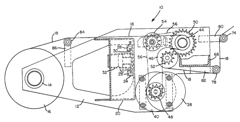
10. The stretch head 10 is seen to comprise a base plate 12,
as best seen in FIGURES 4 and 5, upon one end of which a lower
bearing member 14 is mounted so as to rotatably support a sub-
stantially upstanding or vertically oriented wrapping film
supply roll 16 from which a fresh supply of wrapping film 18
is able to be withdrawn in connection with the performance of
a package, article, or pallet wrapping operation.
A substantially upstanding or vertically oriented
main support frame 20 projects upwardly from a substantially
central portion of the base plate 12, and a steel sheet form
or housing 22 is integrally fixed to and carried by the main
support frame 20. A support bracket 24, having a substantially
reversely or backwardly oriented C-shaped configuration, is
affixed to the main support frame 20 by suitable means, such
as, for example, bolt fasteners 26, and the opposite ends of
the support bracket 24 form slotted rails 28 for accommodating
flanged ends 30 of a vertically oriented downright or support
mast structure 32 upon which the entire stretch head 10 is
vertically reciprocable attendant a film wrapping operation.
The steel sheet form or housing 22 is provided with an upper
support bracket 34 which has an upper bearing member 36 mount-
ed thereon for engaging the upper end of the wrapping film
supply roll 16 and for cooperating with the lower bearing mem-
CA 022~227~ 1998-11-02
ber 14 in rotatably supporting the wrapping film supply roll
16.
Contrary to conventional wrapping machine stretch
heads wherein, for example, the rotary drive for the tension
rolls or stretch rollers is mounted upon an upper support
frame or plate member, as exemplified at 27 and 28, for ex-
ample, as disclosed in FIGURE 1 of the drawings which cor-
responds to FIGURE 2 of the aforenoted Suolahti patent, the
quick thread wrapping machine stretch head of the present in-
lC vention has the rotary drive means thereof located at the bot-
tom of the stretch head, and the upper ends of the tension
rolls or stretch rollers are not connected to each other by,
for example, an upper frame member as is characteristic of the
known prior art systems.
More particularly, as best seen from FIGURES 4 and
5, the opposite end of the base plate 12 of the stretch head
10 has a substantially vertically oriented drive motor 38
mounted thereon, as well as a gear box 40, and the drive motor
38 and the gear box 40 are drivingly interconnected together
by means of suitable gearing 42. At the rear of the base plate
12, there is provided a first tension roll or stretch roller
44 which extends substantially vertically upwardly from the
base plate 12 and which has a relatively small diametrical ex-
tent, and there is also provided a second stretch roller or
tension roll 46 which likewise extends substantially vertical-
ly upwardly from the base plate 12 and which has a relatively
large diametrical extent. The gear box 40 is provided at its
base end with a suitable output gear or sprocket wheel 48, as
best seen in FIGURE 5, and the first, relatively small tension
roll or stretch roller 44 and the second, relatively large
tension roll or stretch roller 46 are respectively provided at
their base ends with relatively large and small sprocket gears
or wheels 50 and 52. An idler gear or sprocket wheel 54 is al-
so mounted upon the base plate 12, and an endless sprocket
.. ..
CA 022~227~ 1998-11-02
chain 56 is routed around the gear box sprocket wheel 48, the
tension roll or stretch roller sprocket wheels 50 and 52, and
the idler sprocket wheel 54 such that rotary drive is trans-
mitted from the motor 38 to the gear box 40, and in turn, from
the gear box 40 to the idler gear or sprocket wheel 54 and the
tension roll or stretch rollers sprocket wheels or gears 50
and 52 so as to rotatably drive the tension rolls or stretch
rollers 44 and 46.
As can be ~urther appreciated from FIGURE 5, the
wrapping film 18 from wrapping film supply roll 16 is routed
around the exterior surfaces of the tension rolls or stretch
rollers 46 in a pattern having a substantially reversed S-
shaped configuration, and in view of the difference in the di-
ametrical extents of the tension rolls or stretch rollers 44
and 46, and their associated sprocket wheels or gears 50 and
52, the wrapping film 18 is stretched to a predeterminedly de-
sired degree. It is also to be noted that the film path around
the tension rolls or stretch rollers 44 and 46, having the
substantially reversed S-shaped configuration, is contrary to
the film path or pattern around the tension rolls or stretch
rollers of the prior art exemplified by Suolahti and Moore et
al. wherein the film paths or patterns of such known prior art
comprise a substantially W-shaped configuration. The substan-
tially S-shaped film path or pattern characteristic of the
present invention provides the wrapping film with better de-
sirable characteristics, such as, for example, tensile
strength or the like, while eliminating or minimizing undesir-
able characteristics, such as, for example, wrapping film
neckdown.
In order to fixedly mount or secure the upper ends
of the tension rolls or stretch rollers 44 and 46 with respect
to the stretch head 10, an angle iron 58 is provided within
the upper region of the stretch head 10 and is seen to com-
prise a first leg portion 60 which is adapted to be fixedly
--10--
. . .
CA 022~227~ 1998-11-02
secured to the main support frame 20 by suitable means, such
as, for example, bolt fasteners, not shown, and a second leg
portion 62 integral with the first leg portion 60 and to which
one end of a first support bracket 64 is secured by suitable
5 means, such as, for example, bolt fasteners, also not shown.
The opposite end of the support bracket 64 is provided with a
suitable rotary bearing 66 within or by means of which the up-
per end of the small tension roll or stretch roller 44 is ro-
tatably mounted, all as best appreciated from FIGURES 3 and 4.
In a somewhat similar manner, as may additionally be
appreciated from FIGURE 5, a substantially vertical upstanding
frame member 68, having a substantially C-shaped cross-sec-
tional configuration, is fixedly secured at its lower end to
the base plate 12, and the upper end of the frame member 68
15 has a second support bracket 7 0 fixedly secured thereto as
best seen in FIGURE 3. One end of the second support bracket
70 is provided with a rotary bearing member 72 for rotatably
supporting the upper end of the large tension roll or stretch
roller 46, and the other opposite end of the second support
20 bracket 70 rotatably supports and mounts the upper end of a
first idler roller 74 around which the wrapping film 18 is
conducted when the wrapping film 18 is being transported to-
ward a wrapping station, not shown, at which an article, pack-
age, or pallet, is disposed so as to be wrapped. A third sup-
25 port bracket 76 is fixedly secured to the second supportbracket 70 by suitable means, such as, for example, bolt fas-
teners, not shown, so as to rotatably support the upper end of
a second idler roller 78 around which the wrapping film 18 is
also conducted, the second idler roller 78 being located along
30 the wrapping film path so as to be interposed between the
large tension roll or stretch roller 46 and the first idler
roller 74.
As best seen in FIGURE 5, fourth and fifth support
brackets 80 and 82 are respectively secured by suitable means,
CA 022~227~ 1998-11-02
such as, for example, bolt fasteners, not shown, to the base
plate 12 so as to respectively rotatably support the lower
ends of the first and second idler rollers 74 and 78. As best
appreciated from FIGURES 3 and 5, a third idler roller 84 is
provided along the wrapping film path so as to be interposed
between the wrapping film supply roll 16 and the first small
tension roll or stretch roller 44, and sixth and seventh sup-
port brackets 86 and 88 are respectively secured by suitable
means, such as, for example, bolt fasteners, not shown, to the
base plate 12 and the steel sheet form or housing 22 so as to
rotatably support the lower and upper ends of the third idler
roller 84.
In utilizing the wrapping film wrapping machine
stretch head apparatus or system 10 of the present invention,
particularly when a new or fresh supply roll 16 of the wrap-
ping film 18 has been installed upon the stretch head 10, the
leading end of the wrapping film 18 is withdrawn from the film
supply roll 16, routed around the idler roller 84, and con-
ducted toward the tension rolls or stretch rollers 44 and 46.
In view of the fact that the upper ends of the tension rolls
or stretch rollers 44 and 46 are respectively rotatably mount-
ed within the mounting or support brackets 64 and 70 which are
separate and independent from each other so as not to be con-
nected to each other, such as, for example, by means of upper
frame members or the like similar to those characteristic of
the known prior art as disclosed within, for example, the
aforenoted Suolahti and Moore et al. patents, the upper end of
the stretch head 10 of the present invention, particularly
within the region or vicinity of the tension rolls or stretch
rollers 44 and 46, is effectively open.
In view of the additional fact that the tension
rolls or stretch rollers 44 and 46 are laterally spaced from
each other, the leading end of the wrapping film 18 may be
partially routed around the small tension roll or stretch
. . ~
CA 022~227~ 1998-11-02
roller 44, subsequently readily and easily inserted between
the tension rolls or stretch rollers 44 and 46 in a substan-
tially vertically downward mode within the space defined be-
tween the tension rolls or stretch rollers 44 and 46 and in a
direction parallel to the longitudinal axes of the tension
rolls or stretch rollers 44 and 46, and routed around the
large tension roll or stretch roller 46 so as to be conducted
further downstream toward the idler rollers 78 and 74.
As can therefore be appreciated, in view of the fact
that the upper region of the stretch head 10, particularly
within the vicinity of the tension rolls or stretch rollers 44
and 46, is open and not closed or covered by means of an upper
frame member as is characteristic of the known prior art such
as that of Suolahti and Moore et al., the wrapping film 18 can
be inserted between and routed around the tension rolls or
stretch rollers 44 and 46 in a substantially vertically down-
ward mode or axial direction, and the need for movable doors
or frame members, upon which tension rolls, press rolls, or
orienting rolls are mounted, and by means of which the wrap-
ping film is inserted in a relatively transverse directionwith respect to the longitudinal or axial extents of the ten-
sion rolls or stretch rollers, is obviated. In addition, the
awkward, difficult, tedious, and time-consuming film threading
operations, likewise characteristic of the prior art systems,
are also effectively eliminated.
It is to be noted that while the upper region of the
stretch head 10 of the wrapping machine of the present inven-
tion is to be open, as defined between the upper ends of the
tension rolls or stretch rollers 44 and 46, and their respect-
ive support brackets 64 and 70, during a wrapping film thread-
ing or routing operation attendant, for example, the installa-
tion of a new wrapping film supply roll 16, so as to in fact
permit the substantially vertically downward insertion of the
leading end of the wrapping film 18 into and within the space
.
CA 022S227S 1998 -11- 02
defined between the tension rolls or stretch rollers 44 and
46, during running of the wrapping film 18 attendant an actual
packaging or wrapping operation with respect to an article,
package, or pallet being wrapped, and wherein, for example, a
relatively heavy gauge wrapping film 18 may be employed, the
respective upper ends of the tension rolls or stretch rollers
44 and 46 may tend to move toward each other under the forces
of the wrapping film 18'which may be impressed thereon.
Under the aforenoted operating conditions, the upper
ends of the tension rolls or stretch rollers 44 and 46 may be
provided with a suitable mechanical stabilizer, spacer, or the
like so as to structurally maintain the stretch rollers or
tension rolls 44 and 46 at their relative dispositions with
respect to each other. Such a stabilizer, spacer, or the like
would of course be movable between a first inoperative posi-
tion at which the upper ends of the tension rolls or stretch
rollers 44 and 46 would no longer be mechanically connected
together whereby the upper end of the stretch head 10 would in
effect be open so as to permit the vertically downward or axi-
al threading of the wrapping film 18 between the tension rollsor stretch rollers 44 and 46, and a second operative position
at which the upper ends of the tension rolls or stretch roll-
ers 44 and 46 would be connected together so as to maintain
the tension rolls or stretch rollers 44 and 46 at their desir-
ed positions predeterminedly spaced from each other.
It is to be lastly noted that the longitudinal ex-
tent or axis of the steel sheet form or housing 22 is oriented
vertically while the base plate 12 is disposed at a predeter-
mined angle with respect to the horizontal so as to permit the
wrapping film 18, which is therefore being discharged at a
relatively downward or inclined angle, to reach the lowermost
elevational levels at the wrapping station, not shown, in
order to be capable of wrapping, for example, palletized
loads. If the base plate 12 was oriented horizontally, the
-14-
CA 022~227~ 1998-11-02
wrapping film 18 would not be able to be disposed at the low-
ermost elevational levels relative to the wrapping station and
the particular load to be wrapped due to the disposition of
the other structural components of the stretch head system,
such as, for example, the downright structure upon which the
stretch head 10 is vertically reciprocable, the provision of
the rotary drive components, that is, the motor 38, the gear-
box 40, and the sprocket wheels 48, 50, 52, 54, and the like,
within the lower region or bottom end of the stretch head 10.
Thus it may be seen that the wrapping machine
stretch head of the present invention overcomes the various
operational and safety drawbacks and disadvantages of the
known prior art systems. By locating the rotary drive means
for the tension rolls or stretch rollers within the bottom or
lower end region of the stretch head, thereby eliminating the
need for an upper support frame member for the rotary drive
system, and by fixedly mounting the upper ends of the tension
rolls or stretch rollers within separate and independent sup-
port brackets whereby the upper ends of the tension rolls or
stretch rollers are not connected to each other, the wrapping
film may be readily and easily inserted, into the space defin-
ed between the tension rolls or stretch rollers, in a substan-
tially vertically downward or axial mode parallel to the lon-
gitudinal axes of the tension rolls or stretch rollers. In
this manner, the awkward, difficult, tedious, and time-consum-
ing threading or routing of the wrapping film beneath the up-
per frame member and between the tension rolls or stretch
rollers is eliminated, as is the need for movable frame mem-
bers, upon which cooperating press or orienting rolls are
mounted, which open and close with respect to the tension
rolls or stretch rollers so as to conventionally permit the
wrapping film to be inserted, routed, or threaded in a direc-
tion transverse to the longitudinal axes of the tension rolls
or stretch rollers.
,_ .. .. ..
, . ~ .
CA 022~227~ 1998-11-02
It is to be lastly noted that while references may
have been made throughout the specification to a particular
orientation of the system components as comprising, for examp-
le, top, bottom, upper, lower, and the like, it is to be un-
derstood that in accordance with the principles and teachingsof the present invention, the various components may be ori-
ented differently than as specifically described, although the
relative orientation or 'disposition of the various components
with respect to each other will remain the same.
Obviously, many modifications and variations of the
present invention are possible in light of the above
teachings. It is therefore to be understood that within the
scope of the appended claims, the present invention may be
practiced otherwise than as specifically described herein.
-16-