Note: Descriptions are shown in the official language in which they were submitted.
CA 02252286 2003-04-22
The present invention relates generally to a field drain panel for water
management.
A patentability search was conducted on the present invention and the
following
U.S. patents were developed:
Patent No. 980,442 discloses a drainage culvert which has an upper corrugated
arched section 3 and a lower flat section 1 with upturned flanges 2 along each
edge.
See Figures 1 and 3. The culvert may include two upper longitudinal sections
as shown
in Figures 1 and 4 such that the ends overlap one full corrugation. The upper
section
includes flanges 4 that fit within the upturned flanges 2 of the flat bottom
section. Bolts
5 may be used to fasten the sections together.
Patent 1,071,185 discloses a metal culvert that includes a flat plate 5 with
longitudinal grooves 7 for receiving an arched cover plate 6 without the use
of fastening
means. See Figures 1 and 2, and lines 36-46 of page 1. Figure 3 shows two
corrugated arched plates overlapped at their ends so that they interlock. See
lines 61-
70 of page 2.
Patent 3,926,222 discloses coupling means on corrugated tubing that includes
corrugations of a reduced depth at 12a where two tubes are coupled together as
compared to the corrugation depths 12 at other sections. See Figures 1-3 and
column
2, lines 34-41.
Patent 4,245,924 discloses an arched conduit suitable for use as drain tubing.
The conduit includes a flat base D and a section having the cross section of a
parabolic
arch. See Figures 1-3 and column 3, lines 36-43. Ribs 22 and 24 are shown on
the
outside.
Patent 4,523,613 discloses a drain conduit which includes a base B of porous
material such as netting or mesh, and a top wall A formed of two layers 60 and
62 of
polyethylene with filler materials. The base and top wall are connected at
their edges
as illustrated in Figures 1 and 2. Apertures 50 at the apex and 52, 54 at the
side walls
are included as shown in Figure 1. The side walls are also corrugated.
Patent 4,650,367 in the Figure 10 construction discloses an extruded plastic
conduit 61 of relatively low profile for use as a roadway underdrain. The
conduit
includes perforations 66 and interior vertical reinforcing walls 62 and 63.
See column
-1-
CA 02252286 1998-10-30
12, lines 4-26. The use of high density polyethylene is discussed in column
13, lines
18-37.
Patent 4,995,759 discloses a ground drainage system that utilizes a plurality
of
corrugated tubes oriented in a side-by-side linear fashion with respect to
each other by
tear portions 19 as shown in Figures 2-5. For drainage use, the tubes may be
arranged
vertically or horizontally as suggested in the paragraph bridging columns 6
and 7.
Patent 5,087,151 discloses the use of high density polyethylene arch-shaped
galleries in drain fields. See column 6, lines 16-18. Figures 12-14 show two
galleries
and 10A with means for coupling the two together. The end wall 28 of gallery
10 is
10 cut off so that rib 18 can be placed over rib 18A' of lesser height on
gallery 10A as
described in column 5, lines 48-65.
Patent 5,720,577 discloses a culvert formed from a plurality of corrugated
sections 22 with outer reinforcing ribs 24 and 26. See Figure 1. The ends of
the
sections 22 are supported in receiving channels 32 over footing pads 28 and 30
as
shown in Figures 2A and 2B. See column 3, lines 45-65.
The field of search included class 138, subclasses 111, 168 and 173; and class
405, subclasses 43, 48, 49, 124 and 126. Examiner Dennis Taylor was also
consulted.
The invention features a field drain panel that has a low profile drainage
panel
manufactured from high molecular weight polyethylene. The field drain panel is
installed using a unique interlocking overlapping rib method. No separate end
plates
are required.
The field drain panel is the most versatile of any innovative septic products
currently available in the marketplace.
It is produced with a standard of four attached elongated arch-shaped channels
approximately one foot wide each, for a total width of four feet. It is also
available in
one foot, two foot and three foot widths. Any of the four widths may be
practical in a
number of specific situations. The field drain panel may be used to design
many lines
having narrow trenches, typically separated by respective minimum separation
orwider
trenches (up to four feet) installed because of limited area of installation.
The field drain panel is only 8.5 inches high and requires a minimum 6 inches
of backfill coverto attain (H-10) residential application traffic demands and
requires only
-2-
CA 02252286 1998-10-30
12 inches of backfill cover under pavement to meet (H-20) cargo-carrying multi-
wheel
vehicle loads.
The field drain panel is also capable of being shortened by trimming with a
hand
saw by the contractor on the job site. The lay-up length of eight feet can be
shortened
at any of the twenty-one four inch increments.
Contractors, designers and regulatory agencies have stated that they believe
there is a need for such a product. With situations of installation of on-site
wastewater
treatment systems in areas of higher restrictive horizon, such as seasonal
high water
or bedrock that would prevent one from going too deep, the field drain panel
is a logical
choice.
Moreover, since 1989 the inventor has promoted the use of his CONTACTORT""
and RECHARGERT"" chambers with a covering of specified geosynthetic filter
fabric.
The fabric performs its apparent function in the prevention of soil intrusion
into the
chamber. However, the main advantage of the fabric is to promote a high degree
of
effluent/soil interface. Over 75% of the fabric is directly exposed to
effluent.
However, the field drain panel may be used in place of the CONTACTORT"" and
RECHARGERT"" chambers for obtaining even better results. When the field drain
panel
of the present invention is used with two to four channels wide, it is only
necessary to
cover the outside chambers (i.e. those in contact with the interfacing soil
sidewall) with
fabric. Likewise, when installed-side-by-side in clustered beds, only the
outside
chambers need to be covered with fabric. In beds, only the bottom (primary)
infiltrative
surface is serviced with no effective sidewall serviced within the chamber
clusters.
The field drain panel promotes over 80% soil/effluent interface on the primary
bottom area and adjacent sidewall to soil area.
Other objects of the invention will in part be obvious and will in part appear
hereinafter.
The invention accordingly comprises the features of construction, combination
of elements, and arrangement of parts which will be exemplified in the
construction
hereinafter set forth, and the scope of the invention will be indicated in the
claims.
-3-
CA 02252286 1998-10-30
For a fuller understanding of the nature and objects of the invention,
reference
should be made to the following detailed description taken in connection with
the
accompanying drawings, not in scale, in which:
Figure 1 is a diagram from a first direction of a basic configuration of a
field drain
panel that is the subject matter of the present application.
Figure 2 is a diagram of one elongated chamber from the basic configuration of
the field drain panel in Figure 1 along lines 2-2 that is the subject matter
of the present
application.
Figures 3-6 show diagrams of four different field drain panel configurations.
Figures 7-14 show diagrams of four different models of field drain panels
having
four elongated chambers.
Figures 15-22 show diagrams offourdifferent models offield drain panels having
a single elongated chamber.
Figures 23-30 show diagrams of fourdifferent models offield drain panels
having
two elongated chambers.
Figures 31-38 show diagrams offourdifferent models offield drain panels having
three elongated chambers.
Figure 39, including Figures 39(a), (b), (c), (d) and (e), show diagrams in
more
detail a field drain C-1 chamber like that shown in Figures 15-22.
Figure 40 shows a diagram of a transverse strengthening rib R1, R2, ..., R22
and
RE shown in Figure 1.
Figure 41 shows a diagram of either of a smaller transverse strengthening end
rib r1, or a smaller transverse strengthening intermediate rib r2 shown in
Figure 1.
Figures 42-45 show a diagram of a parabolic arch conduit generally indicated
as
PAC.
Figure 46 shows a diagram of a typical installation for stream crossings.
Figures 47-49 show a diagram of why a PAC installation shown in Figure 46 is
effective for stream crossings.
Figure 50 shows a chart showing the calculations of effective interface
display
of the ratings for one to four channels used in a trench configuration for
full load
capacity to the top of each arch.
-4-
CA 02252286 1998-10-30
Figure 51 shows a comparison of effective interface of field drain panels to
equal
width of pipe and stone trench.
Figure 52, including Figures 52(a), (b), (c), (d), shows diagrams of an
embodiment of the invention having a plurality of lateral transfer tunnels
similar to that
shown in Figures 2 and 39(a).
In its broadest sense, the present invention features a first molded polymer
field
drain panel made from a moldable polymer sheet material and having an
elongated
chamber with an arched-shape, a first end, a second end and transverse
strengthening
ribs protruding outwardly therebetween.
The elongated chamber has a smaller transverse strengthening end rib, a
transverse strengthening end rib and a smaller transverse strengthening
intermediate
rib.
The smaller transverse strengthening end rib is molded at the first end and
shaped for being embracingly overlapped by a corresponding transverse
strengthening
end rib of a corresponding elongated chamber of a second molded polymer field
drain
panel.
The transverse strengthening end rib is molded at the second end for
overlapping a corresponding smaller transverse strengthening end rib of the
corresponding elongated chamber of the second adjoining molded polymer field
drain
panel.
The smaller transverse strengthening intermediate rib may be molded between
any two transverse strengthening ribs with respect to the first end and the
second end
of the first molded polymer field drain panel for being embracingly overlapped
by the
corresponding transverse strengthening end rib of the corresponding elongated
chamber of the second field drain panel upon severing removal of at least the
transverse strengthening end rib that is molded at the second end of the first
molded
polymer field drain panel.
In one embodiment, the first end is a closed end; the second end is an open
end;
the smaller transverse strengthening intermediate rib is molded as a second-to-
last
transverse strengthening rib molded next to the transverse strengthening end
rib that
is molded at the second end.
-5-
CA 02252286 1998-10-30
With such a construction, the first molded polymer field drain panel is
reversible
for either connecting its open end to a corresponding open end of a second
molded
polymerfield drain panel upon severing removal of at least the transverse
strengthening
end rib of one of the molded polymer field drain panel, or for connecting its
open end
to a corresponding closed end of the second molded polymer field drain panel.
Referring now to Figures 1-5, a field drain panel is shown having a versatile
low
profile 8'/2 inch high chamber system available in various configurations.
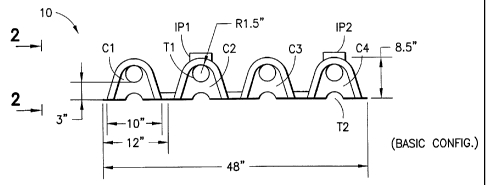
Figure 1 shows a basic configuration of the field drain panel generally
indicated
as 10, having four elongated chambers having a total width of 48 inches. Each
elongated chamber C1, C2, C3, C4 has an outer width of about 12 inches, an
inner
width of about 10 inches, and a height of 8.5 inches. Each elongated chamber
C1, C2,
C3, C4 has four upper circular transfer openings, one of which is labelled T1.
Each
upper circular transfer opening T1 has a radius of 1.5 inches, for forming a
width of 3
inches for fitting PVC pipe. Each elongated chamber C1, C2, C3, C4 has four
lower
semi-circular transfer openings, one of which is labelled T2. The second and
fourth
elongated chambers have one or more inspection or access portals IP1, IP2.
As shown in Figure 2, the elongated chamber C1 has transverse strengthening
ribs R1, R2, ..., R22, a smaller transverse strengthening end rib r1, a
smaller transverse
strengthening intermediate rib r2, and a transverse strengthening end rib RE.
The
elongated chamber C1 also has three lateral transfer tunnels or side transfer
openings,
one of which is labelled T3. The lateral transfer tunnels for allowing
effluent to flow from
the sides, as well as for flexing the field drain panel to contour it to the
terrain. As
shown, the elongated chamber C1 has a length of 96 inches.
Figures 3-6 show diagrams of four different field drain panel configurations.
Figure 3 shows a first configuration having a field drain panel 20 with a
single elongated
arch-shaped chamber 22 similar to that shown in Figure 1, having a transfer
opening
24, a transverse strengthening end rib 26, one inspection or access portal 28
and a
lower semi-circular transfer opening 29. Figure 4 shows a second configuration
having
a field drain panel 20 with two elongated chambers similar 32a, 32b to that
shown in
Figure 2 that are molded adjacent and substantially parallel to one another,
having a
transfer opening 34, transverse strengthening end ribs 36a, 36b, one
inspection or
-6-
CA 02252286 1998-10-30
access portal 38 and lower semi-circular transfer openings 39a, 39b. Figure 5
shows
a third configuration having a field drain panel 40 with three elongated
chambers 42a,
42b, 42c similar to that shown in Figure 2 that are molded adjacent and
substantially
parallel to one another, having a transfer opening 44, transverse
strengthening end ribs
46a, 46b, 46c, one inspection or access portal 48 and lower semi-circular
transfer
openings 49a, 49b, 49c. Figure 6 shows a fourth configuration having a field
drain
panel 50 with four elongated chambers 52a, 52b, 52c, 52d similar to that shown
in
Figure 2 that are molded adjacent and substantially parallel to one another,
having a
transfer opening 54, transverse strengthening end ribs 56a, 56b, 56c, 56d, one
inspection or access portal 58 and lower semi-circular transfer openings 59a,
59b, 59c,
59d. The scope of the invention is not intended to the inspection or access
portal, or
the transfer opening, being located on any particular chamber, or any
particular
dimensionality of the field drain panel.
Figures 7-14 show diagrams of four different models of field drain panels
having
four elongated chambers, which are not described in detail. The models related
to the
different ways that the field drain panel is trimmed by sawing or cutting off
a portion
thereof to build a field drain.
Figures 7-8 show a front and back diagram of a model "S" starter field drain
panel having a large front rib, a back small rib, a front wall with a starter
4.5 inch
transfer opening, back walls with respective upper transfer openings, and one
or more
lower arch openings. The starter transfer opening allows transfer of effluent
for a
starter.
Figures 9-10 show a front and back diagram of a model "I" middle field drain
panel having a large front rib, a back small rib, open fronts, back walls with
respective
3.0 inch upper transfer openings, and one or more lower arch openings.
Figures 11-12 show a front and back diagram of a model "E" end field drain
panel having a large front rib, a back small rib, open fronts, and closed end
back walls.
The model "E" end field drain panel is formed by trimming at a small rib.
Figures 13-14 show a front and back diagram of a model "R" field drain panel
having a large front rib, a back small rib, a front wall with an end 4.5 inch
transfer
opening, and closed back walls.
-7-
CA 02252286 1998-10-30
Figures 15-22 show diagrams offourdifferent models offield drain panels having
a single elongated chamber.
Figures 15-16 show a front and back diagram of a model "S" starter field drain
panel having a front large rib, a back small rib, front and back walls with a
respective
4.5 inch upper transfer opening, and a back arched opening.
Figures 17-18 show a front and back diagram of a model "I" middle field drain
panel having a front large rib, a back small rib, a back wall with a 3.0 inch
upper transfer
opening, and a back arched opening.
Figures 19-20 show a front and back diagram of a model "E" end field drain
panel having a front large rib, a back small rib, and a closed back wall. The
model "E"
end field drain panel is formed by trimming at a small rib.
Figures 21-22 show a front and back diagram of a model "R" field drain panel
having a front large rib, a back small rib, a front wall with a 4.5 inch
opening and a
closed back wall.
Figures 23-30 show diagrams of fourdifferent models of field drain panels
having
two elongated chambers.
Figures 23-24 show a front and back diagram of a model "S" starter field drain
panel having two front large ribs, two back small ribs, a front wall with a
4.5 inch upper
transfer opening, back walls with 4.5 inch upper transfer openings, and back
arched
openings.
Figures 25-26 show a front and back diagram of a model "I" middle field drain
panel having two front large ribs, two back small ribs, back walls with 3.0
inch upper
transfer openings, and back arched openings.
Figures 27-28 show a front and back diagrams of a model "E" end field drain
panel having two front large ribs, two back small ribs, and closed back walls.
The
model "E" end field drain panel is formed by trimming at a small rib.
Figures 29-30 show a front and back view of a model "R" field drain panel
having
two front large ribs, two back small ribs, a front wall with a 4.5 inch
opening, and closed
back walls.
Figures 31-38 show diagrams four different models of field drain panels having
three elongated chambers.
_g_
CA 02252286 1998-10-30
Figures 31-32 show a front and back view of a model "S" starter field drain
panel
having three front large ribs, three back small ribs, a front wall with a 4.5
inch upper
transfer opening, back walls with 4.5 inch upper transfer openings, and back
arched
openings.
Figures 33-34 show a front and back view of a model "I" middle field drain
panel
having three front large ribs, three back small ribs, back walls with 3.0 inch
upper
transfer openings, and back arched openings.
Figures 35-36 show a front and back view of a model "E" end field drain panel
having three front large ribs, three back small ribs, and closed back walls.
The model
"E" end field drain panel is formed by trimming at a small rib.
Figures 37-38 show a front and back view of a model "R" field drain panel
having
three front large ribs, three back small ribs, a front wall with a 4.5 inch
opening, and
closed back walls.
Figure 39, including Figures 39(a), (b), (c) and (d), show in more detail a
field
drain chamber like that shown in Figures 15-22. Figure 39(a) is a side view of
the
elongated chamber. Figure 39(b) is a top view of the elongated chamber. Figure
39(c)
shows a diagram of a cross-sectional looking from right-to-left on the paper
for a
respective model R, model S+I or model E. Figure 39(d) shows a diagram of a
cross-
sectional looking from left-to-right on the paper for a respective model R+S,
model I or
model E. Similar to that shown in Figure 1, the elongated chamber has an outer
width
of about 12 inches, an inner width of about 10 inches, a height of 8.5 inches,
and a
spacing of 4 inches between the transverse strengthening ribs. Inspection
ports are
available on every second chamber.
Figure 40 shows a diagram of either the transverse strengthening rib R1, R2,
...,
R22 or RE shown in Figure 1 that has a height and width of about 1.0625
inches.
Figure 41 shows a diagram of either the smaller transverse strengthening end
rib r1,
or the smaller transverse strengthening intermediate rib r2 in Figure 1, that
each of
which has a height and width of about 0.075 inches. As shown, the transverse
strengthening rib RE has one face formed at a 95 degree angle with respect to
the flat
surface F. For example, in operation the smaller transverse strengthening end
rib r1
of a first molded polymer field drain panel generally indicated as FD1 in
Figure 40 is
_g_
CA 02252286 1998-10-30
embracingly overlapped by a corresponding transverse strengthening end rib RE
of a
corresponding elongated chamber of a second molded polymer field drain panel
generally indicated FD2 in Figure 41.
Figures 42-45 show a parabolic arch conduit generally indicated as PAC that
includes an elongated chamber E and a lock down plate P. The elongated chamber
E has locking edges LE 1, LE2, and strengthening members SM 1, SM2. The lock
down
plate P has overlapping latches OL1, OL2, and inner locking members LM 1, LM2.
Together these features of the PAC cooperate together to lock the elongated
chamber
E to the lock down plate P.
Figure 46 shows a typical installation for stream crossings. In operation,
each
unit fits together with an interlocking rib system. Each unit should be
equipped with a
lock-down plate P shown in Figures 42-45.
Figures 47-49 show why a PAC installation for stream crossings shown in Figure
46 is effective. Figure 47 shows a stream having a height of h1. Figure 48
shows a
stream having a height of h2 with a pipe therein for a stream crossing. Figure
49 shows
a stream having a height of h3 with a PAC system therein for a stream
crossing, and
shows an equation that indicates that the velocity of the water in the pipe is
greater than
the velocity of the stream and the velocity of the water in the PAC. A
comparison of
Figures 48 and 49 shows that the quantity (Q) of the water for the PAC divided
by the
height of the PAC is greater than the quantity (Q) of the water for the pipe
divided by
the height of the pipe.
Figure 50 shows a chart showing the calculations of effective interface
display
of the ratings for one to four channels used in a trench configuration for
full load
capacity to the top of each arch.
Figure 51 shows a comparison of effective interface of field drain panels to
equal
width of pipe and stone trench.
Figures 42-51 show why the PAC is a cost effective alternative to traditional
pipe
steam crossings. By using the PAC stream crossing, one eliminates: (1 ) The
inevitable
erosion of the original bed under a common pipe crossing, (2) costly pavement
repair,
(3) materials shipping costs for large projects, and (4) other headaches.
-10-
CA 02252286 1998-10-30
Figure 52(a) is a diagram of a top view of a field drain panel 100, and Figure
52(b) is a diagram of a side view of the field drain panel 100. The field
drain panel 100
includes an elongated chamber 102 and transverse strengthening ribs 104, 106,
108,
110, 112, 114, ..., 142. The transverse strengthening rib 104 is an end rib,
the
transverse strengthening rib 106 is a small intermediate rib, and the
transverse
strengthening rib 142 is a smaller end rib. The field drain panel 100 includes
a plurality
of transfer tunnels 150, 152, ..., 182 for allowing effluent to pass from the
field drain
panel, as well as for flexing the field drain panel to contour it to the
terrain. As shown
in Figures 52(a), (b), the transfer tunnels 150, 152, ..., 182 are spaced at
about every
five inches. The scope of the invention is not intended to be limited to any
particular
shape of the transfer tunnels 150, 152, ..., 182. The field drain panel 100
also includes
transfer openings in the front and back wall as shown in Figures 52(c), (d).
It will thus be seen that the objects set forth above, and those made apparent
from the preceding description, are efficiently attained and, since certain
changes may
be made in the above construction without departing from the scope of the
invention,
it is intended that all matter contained in the above description or shown in
the
accompanying drawings shall be interpreted as illustrative and not in a
limiting sense.
It is also to be understood that the following claims are intended to cover
all of
the generic and specific features of the invention herein described and all
statements
of the scope of the invention which, as a matter of language, might be said to
fall
therebetween.
-11-