Language selection

Search

Patent 2252517 Summary

Third-party information liability

Some of the information on this Web page has been provided by external sources. The Government of Canada is not responsible for the accuracy, reliability or currency of the information supplied by external sources. Users wishing to rely upon this information should consult directly with the source of the information. Content provided by external sources is not subject to official languages, privacy and accessibility requirements.

Claims and Abstract availability

Any discrepancies in the text and image of the Claims and Abstract are due to differing posting times. Text of the Claims and Abstract are posted:

  • At the time the application is open to public inspection;
  • At the time of issue of the patent (grant).
(12) Patent Application: (11) CA 2252517
(54) English Title: FUEL HEATING SYSTEM USED IN CONJUNCTION WITH STEAM COOLED COMBUSTORS AND TRANSITIONS
(54) French Title: SYSTEME DE CHAUFFAGE DE CARBURANT UTILISE EN ASSOCIATION AVEC DES CHAMBRES DE COMBUSTION ET DES UNITES DE TRANSITION REFROIDIES A LA VAPEUR
Status: Deemed Abandoned and Beyond the Period of Reinstatement - Pending Response to Notice of Disregarded Communication
Bibliographic Data
(51) International Patent Classification (IPC):
  • F02C 7/224 (2006.01)
  • F01K 23/10 (2006.01)
(72) Inventors :
  • LITTLE, DAVID A. (United States of America)
(73) Owners :
  • WESTINGHOUSE ELECTRIC CORPORATION
(71) Applicants :
  • WESTINGHOUSE ELECTRIC CORPORATION (United States of America)
(74) Agent: SMART & BIGGAR LP
(74) Associate agent:
(45) Issued:
(86) PCT Filing Date: 1997-03-27
(87) Open to Public Inspection: 1997-10-30
Availability of licence: N/A
Dedicated to the Public: N/A
(25) Language of filing: English

Patent Cooperation Treaty (PCT): Yes
(86) PCT Filing Number: PCT/US1997/004892
(87) International Publication Number: WO 1997040268
(85) National Entry: 1998-10-22

(30) Application Priority Data:
Application No. Country/Territory Date
08/636,430 (United States of America) 1996-04-23

Abstracts

English Abstract


A system is disclosed that provides for a more efficient combined cycle
turbine system by using heated coolant returning from the gas turbine engine
(40) to pre-heat fuel (25, 10) before that fuel is injected into the combustor
(30). Coolant, such as steam, that is used to cool gas turbine combustors
and/or transitions carries high grade heat energy that was removed from the
top cycle. By returning the heat energy to the incoming fuel, energy is
recovered at a more efficient rate than would result from recovering that heat
energy in the bottom cycle.


French Abstract

Système constituant un système de turbine à cycle mixte plus efficace du fait de l'utilisation du fluide de refroidissement réchauffé en provenance de la turbine à gaz (40) pour préchauffer le carburant (25, 10) avant qu'il soit injecté dans la chambre de combustion (30). Le fluide de refroidissement, par exemple de la vapeur, utilisé pour refroidir les chambres de combustion ou les unités de transition de turbine à gaz véhicule une chaleur de haute température extraite du cycle supérieur. En restituant cette chaleur au carburant d'alimentation, on opère une récupération d'énergie plus efficace que ce ne serait le cas si la chaleur était extraite dans le cycle inférieur.

Claims

Note: Claims are shown in the official language in which they were submitted.

- 7 -
WHAT IS CLAIMED IS:
1. A system for pre-heating fuel in a gas turbine
engine, comprising:
a coolant supply;
a component in the turbine engine having a liner
such that coolant flowing through said component surrounds
said component and absorbs heat, wherein said liner has an
inlet in flow communication with said coolant supply and an
outlet for coolant to exit the liner; and,
a heat exchanger having a flow path for coolant and
flow path for fuel, wherein said flow path for coolant is in
flow communication with the component liner outlet and wherein
said flow path for fuel is disposed within the flow path of
fuel to the turbine engine combustor, such that heat is
transferred from the coolant to the fuel.
2. A system as in claim 1 wherein said coolant is
steam.
3. A system as in claim 1 wherein said coolant is
water.
4. A system as in claim 1 wherein said coolant is
air.
5. A system as in claim 1 wherein said component
is a combustor.

- 8 -
6. A system as in claim 1 wherein said component
is a transition.
7. A system as in claim 1 wherein said component
is a transition/combustor combination.
8. A system as in claim 1 wherein said coolant
supply is provided by a heat recovery steam generator
connected to an exhaust of the turbine engine.
9. A system for pre-heating fuel in a gas turbine
engine, comprising:
a coolant supply;
a combustor and a transition in the turbine engine
having a liner such that coolant flowing through said
combustor and transition surrounds said combustor and
transition and absorbs heat, wherein said liner has an inlet
in flow communication with said coolant supply and an outlet
for coolant to exit the liner; and,
means for transferring heat from the coolant supply
exiting said outlet to fuel entering the gas turbine engine.
10. A system as in claim 9 wherein said means
comprise a heat exchanger.
11. A system as in claim 9 wherein said coolant is
steam.
12. A system as in claim 9 wherein said coolant is
water.
13. A system as in claim 9 wherein said coolant is
air.
14. A system for pre-heating fuel in a gas turbine
engine, comprising:
a steam supply;

- 9 -
a combustor and a transition in the turbine engine
having a liner such that steam flowing through said combustor
and transition surrounds said combustor and transition and
absorbs heat, wherein said liner has an inlet in flow
communication with said steam supply and an outlet for steam
to exit the liner; and,
a heat exchanger having a flow path for steam and
flow path for fuel, wherein said flow path for steam is in
flow communication with the component liner outlet and wherein
said flow path for fuel is disposed within the flow path of
fuel to the turbine engine combustor, such that heat is
transferred from the steam to the fuel.

Description

Note: Descriptions are shown in the official language in which they were submitted.


CA 022~2~17 1998-10-22
WO 97140268 PCTIUS97/04892
FUEL HEATING SYSTEM USED IN CONJUNCTION WITH STEAM COO~ED
COMBUSTORS AND TR~NS ITIONS
~ield of the Invention
The invention relates to energy recovery systems for
use with turbine engines. More particularly, the invention
relates to a system for transferring energy to fuel from steam
that was used to cool gas turbine combustors and transitions.
BACKG~OUND QF THE INVENTION
Improving the efficiency of power generation systems
is a incessant goal of practitioners in the power generation
system arts. Perhaps the most significant technique for
improving efficiency of power generation is through the use
of a combined cycle system. In a combined cycle system,
exhaust heat from a first system, referred to as the top
cycle, is used to generate power in a second system, referred
to as the bottom cycle. Such combined cycle systems typically
employ a gas turbine engine in the top cycle, and a steam
system in the bottom cycle. A heat recovery steam generator
converts the hot exhaust gas from the gas turbine engine into
useful steam to drive one or more steam turbines.
Developers of power generation systems have
additionally recognized that putting as much energy as
possible into the top cycle yields the greatest energy
- efficiency in combined cycle systems. Energy put into the top
cycle reaps the benefit of delivering energy to both the top
and the bottom cycle. On the other hand, energy put solely
into the bottom cycle delivers energy to only one cycle -- the
bottom. In current high-efficiency power generation systems,
, .. . .. -- , .. ... .

CA 022~2~l7 l998-l0-22
W097/40268 PCT~S97/04892
-- 2
for example, energy input at the top cycle is recovered at
approximately a 58 percent rate from the combined efficiency
of the top and the bottom cycle. By comparison, energy put
into only the bottom cycle is recovered at a significantly
lower 43 percent rate.
In addition to efficiency, cooling the turbine
engines in the power system is also of critical importance.
In particular, the combustors and transitions of gas turbine
engines are exposed to extreme heat and require substantial
cooling. For example, conventional gas turbine engines have
flame temperatures in the combustor that reach 1550~C. To
provide adequate component cooling, turbine engine designers
have used film cooling of combustors and transitions with
pressurized air. As a result of such film cooling techniques,
turbine inlet temperatures fall substantially lower than flame
temperatures (e.g., approximately 1350 versus 1550~C).
However, reducing the turbine inlet temperature in this way
has the unfortunate side effect of decreasing power generation
system efficiency. But, 1550~C is the theoretical limit for
9 ppm dry low N0x (oxides of nitrogen) combustion flame
temperatures - the current industry requirement. To raise
efficiency, combustor and transition cooling designs are
migrating to closed systems in which the coolant is not bled
into the gas path, but rather circulates around the component,
thus allowing a 150~ increase in turbine inlet temperature
without raising flame temperature.
In closed systems, coolant may comprise steam,
water, or air. Where steam is the selected coolant, it is
often removed from the bottom cycle, i.e., from the heat
recovery steam generator, and used to cool components in the
turbine engine. After cooling the combustor and transition;
the steam is routed to a steam turbine where useful energy is
recovered.
Applicant has recognized that routing the steam to
the bottom cycle imposes a penalty on the amount of heat
energy recovered. By not recovering the heat energy in the
top cycle, high grade heat energy is removed from the top

CA 022~2~17 1998-10-22
W097/4~268 PCT~S97/04892
cycle and recovered by the bottom cycle via a steam turbine.
Thus, there is a need for a system of returning the high grade
heat energy removed from the combustors and transitions to the
top cycle.
SUMMARY OF THE INVEN~ION
The present system meets the need above by using
heated coolant returning from the gas turbine engine to pre-
heat fuel before that fuel is injected into the combustor.
Such a system comprises a coolant supply. A component in the
turbine engine having a liner such that coolant flowing
through the component surrounds it and absorbs heat in the
component generated by the hot gas path. That liner has an
inlet for receiving coolant from the coolant supply and an
outlet for coolant to exit the liner. The system also has a
heat exchanger that has a flow path for coolant and a separate
flow path for fuel. Coolant flows from the component liner
outlet and into the heat exchanger. Simultaneously, fuel
flows through the heat exchanger in route to the turbine
engine combustor. Within the heat exchanger, heat from the
coolant is transferred to the fuel.
BRIEF DESCRIPTION OF THE DRAWINGS
The foregoing summary, as well as the following
detailed description of the preferred embodiment, is better
understood when read in conjunction with the appended
drawings. For the purpose of illustrating the invention,
there is shown in the drawings an embodiment that is presently
preferred, it being understood, however, that the invention
is not limited to the specific methods and instrumentalities
disclosed.
In the drawings:
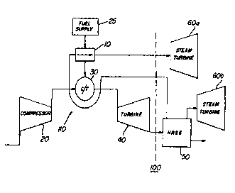
FIGURE 1 is a schematic diagram of a combined cycle
generation system with steam cooled combustor/transitions
employing the present invention;
FIGURE 2 is a block diagram of the
combustor/transition coolant circuit wherein the present
invention is employed.

CA 022~2~l7 l998-l0-22
W097/40268 PCT~S97/04892
DETAILED DESCRIPTION OF A PREFERRED EMBODIMENT
Referring now to the drawings wherein like numerals
indicate like elements throughout, FIGURE 1 presents a
schematic diagram of a combined cycle power generation system
100 wherein the present invention is employed. The top cycle
consists of gas turbine engine 110 and the bottom cycle
consists of heat recovery steam generator (HRSG) 50 and steam
turbines 60. The fuel supply 25 provides the energy source
to the system 100. That fuel from that supply 25, initially,
powers the gas turbine 110. To further enhance the overall
system efficiency, hot gas exiting the turbine 40 as exhaust
is converted to steam by HRSG 50. That steam is used to power
steam turbines 60.
According to a presently preferred embodiment of the
present invention, the combustors and transitions 30 are
cooled by steam provided from the HRSG 50. However, it should
be understood that the source of the steam used to cool the
combustors and turbines 30 can be from any accessible source.
Additionally, notice that the combustors and transitions are
represented by a single element 30 in the FIGUREs.
Significantly, the invention envisions the use of steam that
was used to cool a transition, a combustor, or a combined
combustor/transition. Thus, they are represented in the
FIGUREs as a single element. The steam enters the liner of
the combustors and transitions and cools the walls of the
combustors and transitions by absorbing heat. If the heat
absorbed by the steam were delivered directly to the bottom
cycle, i.e., the steam turbine 60, the energy transferred to
the coolant would be recovered at on~y the bottom cycle
efficiency.
The present invention can be better understood by
reference to a exemplary implementation; however, it should
be appreciated that all the numbers used herein for
temperatures, efficiencies and the like are for illustration
purposes and are not intended to limit the invention. In an
exemplary steam-cooled gas turbine engine, the temperature of
the cooling steam entering the combustor and transition liners

CA 022~2~l7 l998-l0-22
W097/40268 PCT~S97/0~92
approaches 650~F. After the steam travels through and exits
the liner, the temperature will have risen to approximately
1050~F. According to an aspect of the present invention, a
portion of that energy (i-e., the additional heat added to the
steam) is recovered in the top cycle. Thus, according to a
presently preferred embodiment, a heat exchanger 10 is
inserted into the system 100. This heat exchanger 10
transfers some of the heat energy in the steam to the fuel
that enters the top of the cycle via fuel supply 25.
Referring now to FIGURE 2, a block diagram of the
system for transferring high grade heat in the steam to the
fuel is depicted. Initially, the fuel is supplied to the
system at a predetermined temperature. As shown in the
example of FIGURE 2, the fuel leaves the fuel supply 25 at
approximately 59~F. After leaving the fuel supply 25, the
fuel may enter any conventional gas fuel heating system 12.
Conventionally, such systems 12 will raise the temperature
of the fuel to approximately 800~F. After exiting heating
system 12, the fuel enters the heat exchanger 10 of the
present invention. Coincidentally, steam, with a temperature
of approximately 650~F, enters the liner 32 of the combustors
and transitions 30 of the gas turbine engine 110 via inlet 34.
The heat flux from the walls of the liner 32 increases the
steam temperature to approximately 1050~F. The steam then
exits the liner 32 via outlet 36. The steam then enters the
heat exchanger 10, raising the temperature of the fuel to
approximately 900~F. While raising the temperature of the
fuel to 900~F, the temperature of the steam will decrease to
approximately 850~F.
The heat exchanger 10 is of a type well-known in the
art for exchanging heat between separate isolated fluids such
as a compact printed circuit board construction.
The present invention may be embodied in other
specific forms without departing from the spirit or essential
attributes thereofi for example, a similar technique could be
utilized to preheat the fuel using water rather than steam as
depicted in the FIGURES. Accordingly, reference should be

CA 02252517 1998-10-22
WO 97/40268 PCT/US97/04892
made to the appended claims, rather than to the foregoing
specification, as indicating the scope of the invention.

Representative Drawing
A single figure which represents the drawing illustrating the invention.
Administrative Status

2024-08-01:As part of the Next Generation Patents (NGP) transition, the Canadian Patents Database (CPD) now contains a more detailed Event History, which replicates the Event Log of our new back-office solution.

Please note that "Inactive:" events refers to events no longer in use in our new back-office solution.

For a clearer understanding of the status of the application/patent presented on this page, the site Disclaimer , as well as the definitions for Patent , Event History , Maintenance Fee  and Payment History  should be consulted.

Event History

Description Date
Inactive: IPC from MCD 2006-03-12
Inactive: Dead - RFE never made 2003-03-27
Deemed Abandoned - Failure to Respond to Maintenance Fee Notice 2003-03-27
Application Not Reinstated by Deadline 2003-03-27
Inactive: Abandon-RFE+Late fee unpaid-Correspondence sent 2002-03-27
Classification Modified 1999-01-06
Inactive: IPC assigned 1999-01-06
Inactive: First IPC assigned 1999-01-06
Inactive: Notice - National entry - No RFE 1998-12-15
Application Received - PCT 1998-12-11
Application Published (Open to Public Inspection) 1997-10-30

Abandonment History

Abandonment Date Reason Reinstatement Date
2003-03-27

Maintenance Fee

The last payment was received on 2002-02-25

Note : If the full payment has not been received on or before the date indicated, a further fee may be required which may be one of the following

  • the reinstatement fee;
  • the late payment fee; or
  • additional fee to reverse deemed expiry.

Please refer to the CIPO Patent Fees web page to see all current fee amounts.

Fee History

Fee Type Anniversary Year Due Date Paid Date
Registration of a document 1998-10-22
Basic national fee - standard 1998-10-22
MF (application, 2nd anniv.) - standard 02 1999-03-29 1999-03-18
MF (application, 3rd anniv.) - standard 03 2000-03-27 2000-02-18
MF (application, 4th anniv.) - standard 04 2001-03-27 2001-02-21
MF (application, 5th anniv.) - standard 05 2002-03-27 2002-02-25
Owners on Record

Note: Records showing the ownership history in alphabetical order.

Current Owners on Record
WESTINGHOUSE ELECTRIC CORPORATION
Past Owners on Record
DAVID A. LITTLE
Past Owners that do not appear in the "Owners on Record" listing will appear in other documentation within the application.
Documents

To view selected files, please enter reCAPTCHA code :


To view images, click a link in the Document Description column. To download the documents, select one or more checkboxes in the first column and then click the "Download Selected in PDF format (Zip Archive)" or the "Download Selected as Single PDF" button.

List of published and non-published patent-specific documents on the CPD .

If you have any difficulty accessing content, you can call the Client Service Centre at 1-866-997-1936 or send them an e-mail at CIPO Client Service Centre.


Document
Description 
Date
(yyyy-mm-dd) 
Number of pages   Size of Image (KB) 
Representative drawing 1999-01-26 1 6
Description 1998-10-22 6 265
Abstract 1998-10-22 1 45
Drawings 1998-10-22 2 31
Claims 1998-10-22 3 77
Cover Page 1999-01-26 1 46
Reminder of maintenance fee due 1998-12-14 1 110
Notice of National Entry 1998-12-15 1 192
Courtesy - Certificate of registration (related document(s)) 1998-12-15 1 114
Reminder - Request for Examination 2001-11-28 1 118
Courtesy - Abandonment Letter (Request for Examination) 2002-05-22 1 173
Courtesy - Abandonment Letter (Maintenance Fee) 2003-04-24 1 176
PCT 1998-10-22 9 316