Sélection de la langue

Search

Sommaire du brevet 2252517 

Énoncé de désistement de responsabilité concernant l'information provenant de tiers

Une partie des informations de ce site Web a été fournie par des sources externes. Le gouvernement du Canada n'assume aucune responsabilité concernant la précision, l'actualité ou la fiabilité des informations fournies par les sources externes. Les utilisateurs qui désirent employer cette information devraient consulter directement la source des informations. Le contenu fourni par les sources externes n'est pas assujetti aux exigences sur les langues officielles, la protection des renseignements personnels et l'accessibilité.

Disponibilité de l'Abrégé et des Revendications

L'apparition de différences dans le texte et l'image des Revendications et de l'Abrégé dépend du moment auquel le document est publié. Les textes des Revendications et de l'Abrégé sont affichés :

  • lorsque la demande peut être examinée par le public;
  • lorsque le brevet est émis (délivrance).
(12) Demande de brevet: (11) CA 2252517
(54) Titre français: SYSTEME DE CHAUFFAGE DE CARBURANT UTILISE EN ASSOCIATION AVEC DES CHAMBRES DE COMBUSTION ET DES UNITES DE TRANSITION REFROIDIES A LA VAPEUR
(54) Titre anglais: FUEL HEATING SYSTEM USED IN CONJUNCTION WITH STEAM COOLED COMBUSTORS AND TRANSITIONS
Statut: Réputée abandonnée et au-delà du délai pour le rétablissement - en attente de la réponse à l’avis de communication rejetée
Données bibliographiques
(51) Classification internationale des brevets (CIB):
  • F02C 7/224 (2006.01)
  • F01K 23/10 (2006.01)
(72) Inventeurs :
  • LITTLE, DAVID A. (Etats-Unis d'Amérique)
(73) Titulaires :
  • WESTINGHOUSE ELECTRIC CORPORATION
(71) Demandeurs :
  • WESTINGHOUSE ELECTRIC CORPORATION (Etats-Unis d'Amérique)
(74) Agent: SMART & BIGGAR LP
(74) Co-agent:
(45) Délivré:
(86) Date de dépôt PCT: 1997-03-27
(87) Mise à la disponibilité du public: 1997-10-30
Licence disponible: S.O.
Cédé au domaine public: S.O.
(25) Langue des documents déposés: Anglais

Traité de coopération en matière de brevets (PCT): Oui
(86) Numéro de la demande PCT: PCT/US1997/004892
(87) Numéro de publication internationale PCT: WO 1997040268
(85) Entrée nationale: 1998-10-22

(30) Données de priorité de la demande:
Numéro de la demande Pays / territoire Date
08/636,430 (Etats-Unis d'Amérique) 1996-04-23

Abrégés

Abrégé français

Système constituant un système de turbine à cycle mixte plus efficace du fait de l'utilisation du fluide de refroidissement réchauffé en provenance de la turbine à gaz (40) pour préchauffer le carburant (25, 10) avant qu'il soit injecté dans la chambre de combustion (30). Le fluide de refroidissement, par exemple de la vapeur, utilisé pour refroidir les chambres de combustion ou les unités de transition de turbine à gaz véhicule une chaleur de haute température extraite du cycle supérieur. En restituant cette chaleur au carburant d'alimentation, on opère une récupération d'énergie plus efficace que ce ne serait le cas si la chaleur était extraite dans le cycle inférieur.


Abrégé anglais


A system is disclosed that provides for a more efficient combined cycle
turbine system by using heated coolant returning from the gas turbine engine
(40) to pre-heat fuel (25, 10) before that fuel is injected into the combustor
(30). Coolant, such as steam, that is used to cool gas turbine combustors
and/or transitions carries high grade heat energy that was removed from the
top cycle. By returning the heat energy to the incoming fuel, energy is
recovered at a more efficient rate than would result from recovering that heat
energy in the bottom cycle.

Revendications

Note : Les revendications sont présentées dans la langue officielle dans laquelle elles ont été soumises.


- 7 -
WHAT IS CLAIMED IS:
1. A system for pre-heating fuel in a gas turbine
engine, comprising:
a coolant supply;
a component in the turbine engine having a liner
such that coolant flowing through said component surrounds
said component and absorbs heat, wherein said liner has an
inlet in flow communication with said coolant supply and an
outlet for coolant to exit the liner; and,
a heat exchanger having a flow path for coolant and
flow path for fuel, wherein said flow path for coolant is in
flow communication with the component liner outlet and wherein
said flow path for fuel is disposed within the flow path of
fuel to the turbine engine combustor, such that heat is
transferred from the coolant to the fuel.
2. A system as in claim 1 wherein said coolant is
steam.
3. A system as in claim 1 wherein said coolant is
water.
4. A system as in claim 1 wherein said coolant is
air.
5. A system as in claim 1 wherein said component
is a combustor.

- 8 -
6. A system as in claim 1 wherein said component
is a transition.
7. A system as in claim 1 wherein said component
is a transition/combustor combination.
8. A system as in claim 1 wherein said coolant
supply is provided by a heat recovery steam generator
connected to an exhaust of the turbine engine.
9. A system for pre-heating fuel in a gas turbine
engine, comprising:
a coolant supply;
a combustor and a transition in the turbine engine
having a liner such that coolant flowing through said
combustor and transition surrounds said combustor and
transition and absorbs heat, wherein said liner has an inlet
in flow communication with said coolant supply and an outlet
for coolant to exit the liner; and,
means for transferring heat from the coolant supply
exiting said outlet to fuel entering the gas turbine engine.
10. A system as in claim 9 wherein said means
comprise a heat exchanger.
11. A system as in claim 9 wherein said coolant is
steam.
12. A system as in claim 9 wherein said coolant is
water.
13. A system as in claim 9 wherein said coolant is
air.
14. A system for pre-heating fuel in a gas turbine
engine, comprising:
a steam supply;

- 9 -
a combustor and a transition in the turbine engine
having a liner such that steam flowing through said combustor
and transition surrounds said combustor and transition and
absorbs heat, wherein said liner has an inlet in flow
communication with said steam supply and an outlet for steam
to exit the liner; and,
a heat exchanger having a flow path for steam and
flow path for fuel, wherein said flow path for steam is in
flow communication with the component liner outlet and wherein
said flow path for fuel is disposed within the flow path of
fuel to the turbine engine combustor, such that heat is
transferred from the steam to the fuel.

Description

Note : Les descriptions sont présentées dans la langue officielle dans laquelle elles ont été soumises.

CA 022~2~17 1998-10-22
WO 97140268 PCTIUS97/04892
FUEL HEATING SYSTEM USED IN CONJUNCTION WITH STEAM COO~ED
COMBUSTORS AND TR~NS ITIONS
~ield of the Invention
The invention relates to energy recovery systems for
use with turbine engines. More particularly, the invention
relates to a system for transferring energy to fuel from steam
that was used to cool gas turbine combustors and transitions.
BACKG~OUND QF THE INVENTION
Improving the efficiency of power generation systems
is a incessant goal of practitioners in the power generation
system arts. Perhaps the most significant technique for
improving efficiency of power generation is through the use
of a combined cycle system. In a combined cycle system,
exhaust heat from a first system, referred to as the top
cycle, is used to generate power in a second system, referred
to as the bottom cycle. Such combined cycle systems typically
employ a gas turbine engine in the top cycle, and a steam
system in the bottom cycle. A heat recovery steam generator
converts the hot exhaust gas from the gas turbine engine into
useful steam to drive one or more steam turbines.
Developers of power generation systems have
additionally recognized that putting as much energy as
possible into the top cycle yields the greatest energy
- efficiency in combined cycle systems. Energy put into the top
cycle reaps the benefit of delivering energy to both the top
and the bottom cycle. On the other hand, energy put solely
into the bottom cycle delivers energy to only one cycle -- the
bottom. In current high-efficiency power generation systems,
, .. . .. -- , .. ... .

CA 022~2~l7 l998-l0-22
W097/40268 PCT~S97/04892
-- 2
for example, energy input at the top cycle is recovered at
approximately a 58 percent rate from the combined efficiency
of the top and the bottom cycle. By comparison, energy put
into only the bottom cycle is recovered at a significantly
lower 43 percent rate.
In addition to efficiency, cooling the turbine
engines in the power system is also of critical importance.
In particular, the combustors and transitions of gas turbine
engines are exposed to extreme heat and require substantial
cooling. For example, conventional gas turbine engines have
flame temperatures in the combustor that reach 1550~C. To
provide adequate component cooling, turbine engine designers
have used film cooling of combustors and transitions with
pressurized air. As a result of such film cooling techniques,
turbine inlet temperatures fall substantially lower than flame
temperatures (e.g., approximately 1350 versus 1550~C).
However, reducing the turbine inlet temperature in this way
has the unfortunate side effect of decreasing power generation
system efficiency. But, 1550~C is the theoretical limit for
9 ppm dry low N0x (oxides of nitrogen) combustion flame
temperatures - the current industry requirement. To raise
efficiency, combustor and transition cooling designs are
migrating to closed systems in which the coolant is not bled
into the gas path, but rather circulates around the component,
thus allowing a 150~ increase in turbine inlet temperature
without raising flame temperature.
In closed systems, coolant may comprise steam,
water, or air. Where steam is the selected coolant, it is
often removed from the bottom cycle, i.e., from the heat
recovery steam generator, and used to cool components in the
turbine engine. After cooling the combustor and transition;
the steam is routed to a steam turbine where useful energy is
recovered.
Applicant has recognized that routing the steam to
the bottom cycle imposes a penalty on the amount of heat
energy recovered. By not recovering the heat energy in the
top cycle, high grade heat energy is removed from the top

CA 022~2~17 1998-10-22
W097/4~268 PCT~S97/04892
cycle and recovered by the bottom cycle via a steam turbine.
Thus, there is a need for a system of returning the high grade
heat energy removed from the combustors and transitions to the
top cycle.
SUMMARY OF THE INVEN~ION
The present system meets the need above by using
heated coolant returning from the gas turbine engine to pre-
heat fuel before that fuel is injected into the combustor.
Such a system comprises a coolant supply. A component in the
turbine engine having a liner such that coolant flowing
through the component surrounds it and absorbs heat in the
component generated by the hot gas path. That liner has an
inlet for receiving coolant from the coolant supply and an
outlet for coolant to exit the liner. The system also has a
heat exchanger that has a flow path for coolant and a separate
flow path for fuel. Coolant flows from the component liner
outlet and into the heat exchanger. Simultaneously, fuel
flows through the heat exchanger in route to the turbine
engine combustor. Within the heat exchanger, heat from the
coolant is transferred to the fuel.
BRIEF DESCRIPTION OF THE DRAWINGS
The foregoing summary, as well as the following
detailed description of the preferred embodiment, is better
understood when read in conjunction with the appended
drawings. For the purpose of illustrating the invention,
there is shown in the drawings an embodiment that is presently
preferred, it being understood, however, that the invention
is not limited to the specific methods and instrumentalities
disclosed.
In the drawings:
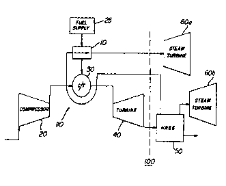
FIGURE 1 is a schematic diagram of a combined cycle
generation system with steam cooled combustor/transitions
employing the present invention;
FIGURE 2 is a block diagram of the
combustor/transition coolant circuit wherein the present
invention is employed.

CA 022~2~l7 l998-l0-22
W097/40268 PCT~S97/04892
DETAILED DESCRIPTION OF A PREFERRED EMBODIMENT
Referring now to the drawings wherein like numerals
indicate like elements throughout, FIGURE 1 presents a
schematic diagram of a combined cycle power generation system
100 wherein the present invention is employed. The top cycle
consists of gas turbine engine 110 and the bottom cycle
consists of heat recovery steam generator (HRSG) 50 and steam
turbines 60. The fuel supply 25 provides the energy source
to the system 100. That fuel from that supply 25, initially,
powers the gas turbine 110. To further enhance the overall
system efficiency, hot gas exiting the turbine 40 as exhaust
is converted to steam by HRSG 50. That steam is used to power
steam turbines 60.
According to a presently preferred embodiment of the
present invention, the combustors and transitions 30 are
cooled by steam provided from the HRSG 50. However, it should
be understood that the source of the steam used to cool the
combustors and turbines 30 can be from any accessible source.
Additionally, notice that the combustors and transitions are
represented by a single element 30 in the FIGUREs.
Significantly, the invention envisions the use of steam that
was used to cool a transition, a combustor, or a combined
combustor/transition. Thus, they are represented in the
FIGUREs as a single element. The steam enters the liner of
the combustors and transitions and cools the walls of the
combustors and transitions by absorbing heat. If the heat
absorbed by the steam were delivered directly to the bottom
cycle, i.e., the steam turbine 60, the energy transferred to
the coolant would be recovered at on~y the bottom cycle
efficiency.
The present invention can be better understood by
reference to a exemplary implementation; however, it should
be appreciated that all the numbers used herein for
temperatures, efficiencies and the like are for illustration
purposes and are not intended to limit the invention. In an
exemplary steam-cooled gas turbine engine, the temperature of
the cooling steam entering the combustor and transition liners

CA 022~2~l7 l998-l0-22
W097/40268 PCT~S97/0~92
approaches 650~F. After the steam travels through and exits
the liner, the temperature will have risen to approximately
1050~F. According to an aspect of the present invention, a
portion of that energy (i-e., the additional heat added to the
steam) is recovered in the top cycle. Thus, according to a
presently preferred embodiment, a heat exchanger 10 is
inserted into the system 100. This heat exchanger 10
transfers some of the heat energy in the steam to the fuel
that enters the top of the cycle via fuel supply 25.
Referring now to FIGURE 2, a block diagram of the
system for transferring high grade heat in the steam to the
fuel is depicted. Initially, the fuel is supplied to the
system at a predetermined temperature. As shown in the
example of FIGURE 2, the fuel leaves the fuel supply 25 at
approximately 59~F. After leaving the fuel supply 25, the
fuel may enter any conventional gas fuel heating system 12.
Conventionally, such systems 12 will raise the temperature
of the fuel to approximately 800~F. After exiting heating
system 12, the fuel enters the heat exchanger 10 of the
present invention. Coincidentally, steam, with a temperature
of approximately 650~F, enters the liner 32 of the combustors
and transitions 30 of the gas turbine engine 110 via inlet 34.
The heat flux from the walls of the liner 32 increases the
steam temperature to approximately 1050~F. The steam then
exits the liner 32 via outlet 36. The steam then enters the
heat exchanger 10, raising the temperature of the fuel to
approximately 900~F. While raising the temperature of the
fuel to 900~F, the temperature of the steam will decrease to
approximately 850~F.
The heat exchanger 10 is of a type well-known in the
art for exchanging heat between separate isolated fluids such
as a compact printed circuit board construction.
The present invention may be embodied in other
specific forms without departing from the spirit or essential
attributes thereofi for example, a similar technique could be
utilized to preheat the fuel using water rather than steam as
depicted in the FIGURES. Accordingly, reference should be

CA 02252517 1998-10-22
WO 97/40268 PCT/US97/04892
made to the appended claims, rather than to the foregoing
specification, as indicating the scope of the invention.

Dessin représentatif
Une figure unique qui représente un dessin illustrant l'invention.
États administratifs

2024-08-01 : Dans le cadre de la transition vers les Brevets de nouvelle génération (BNG), la base de données sur les brevets canadiens (BDBC) contient désormais un Historique d'événement plus détaillé, qui reproduit le Journal des événements de notre nouvelle solution interne.

Veuillez noter que les événements débutant par « Inactive : » se réfèrent à des événements qui ne sont plus utilisés dans notre nouvelle solution interne.

Pour une meilleure compréhension de l'état de la demande ou brevet qui figure sur cette page, la rubrique Mise en garde , et les descriptions de Brevet , Historique d'événement , Taxes périodiques et Historique des paiements devraient être consultées.

Historique d'événement

Description Date
Inactive : CIB de MCD 2006-03-12
Inactive : Morte - RE jamais faite 2003-03-27
Réputée abandonnée - omission de répondre à un avis sur les taxes pour le maintien en état 2003-03-27
Demande non rétablie avant l'échéance 2003-03-27
Inactive : Abandon.-RE+surtaxe impayées-Corr envoyée 2002-03-27
Symbole de classement modifié 1999-01-06
Inactive : CIB attribuée 1999-01-06
Inactive : CIB en 1re position 1999-01-06
Inactive : Notice - Entrée phase nat. - Pas de RE 1998-12-15
Demande reçue - PCT 1998-12-11
Demande publiée (accessible au public) 1997-10-30

Historique d'abandonnement

Date d'abandonnement Raison Date de rétablissement
2003-03-27

Taxes périodiques

Le dernier paiement a été reçu le 2002-02-25

Avis : Si le paiement en totalité n'a pas été reçu au plus tard à la date indiquée, une taxe supplémentaire peut être imposée, soit une des taxes suivantes :

  • taxe de rétablissement ;
  • taxe pour paiement en souffrance ; ou
  • taxe additionnelle pour le renversement d'une péremption réputée.

Veuillez vous référer à la page web des taxes sur les brevets de l'OPIC pour voir tous les montants actuels des taxes.

Historique des taxes

Type de taxes Anniversaire Échéance Date payée
Enregistrement d'un document 1998-10-22
Taxe nationale de base - générale 1998-10-22
TM (demande, 2e anniv.) - générale 02 1999-03-29 1999-03-18
TM (demande, 3e anniv.) - générale 03 2000-03-27 2000-02-18
TM (demande, 4e anniv.) - générale 04 2001-03-27 2001-02-21
TM (demande, 5e anniv.) - générale 05 2002-03-27 2002-02-25
Titulaires au dossier

Les titulaires actuels et antérieures au dossier sont affichés en ordre alphabétique.

Titulaires actuels au dossier
WESTINGHOUSE ELECTRIC CORPORATION
Titulaires antérieures au dossier
DAVID A. LITTLE
Les propriétaires antérieurs qui ne figurent pas dans la liste des « Propriétaires au dossier » apparaîtront dans d'autres documents au dossier.
Documents

Pour visionner les fichiers sélectionnés, entrer le code reCAPTCHA :


Pour visualiser une image, cliquer sur un lien dans la colonne description du document. Pour télécharger l'image (les images), cliquer l'une ou plusieurs cases à cocher dans la première colonne et ensuite cliquer sur le bouton "Télécharger sélection en format PDF (archive Zip)" ou le bouton "Télécharger sélection (en un fichier PDF fusionné)".

Liste des documents de brevet publiés et non publiés sur la BDBC .

Si vous avez des difficultés à accéder au contenu, veuillez communiquer avec le Centre de services à la clientèle au 1-866-997-1936, ou envoyer un courriel au Centre de service à la clientèle de l'OPIC.


Description du
Document 
Date
(aaaa-mm-jj) 
Nombre de pages   Taille de l'image (Ko) 
Dessin représentatif 1999-01-26 1 6
Description 1998-10-22 6 265
Abrégé 1998-10-22 1 45
Dessins 1998-10-22 2 31
Revendications 1998-10-22 3 77
Page couverture 1999-01-26 1 46
Rappel de taxe de maintien due 1998-12-14 1 110
Avis d'entree dans la phase nationale 1998-12-15 1 192
Courtoisie - Certificat d'enregistrement (document(s) connexe(s)) 1998-12-15 1 114
Rappel - requête d'examen 2001-11-28 1 118
Courtoisie - Lettre d'abandon (requête d'examen) 2002-05-22 1 173
Courtoisie - Lettre d'abandon (taxe de maintien en état) 2003-04-24 1 176
PCT 1998-10-22 9 316