Note: Descriptions are shown in the official language in which they were submitted.
CA 02252690 1998-10-27
W O 97/41194 PCT/US97/07095
..
COAL PREPARATION SYSTEM
BACKGROUND OF THE INVENTION
Fleld of the Invention
The present invention relates to a system for preparing coal. More particularly,the invention relates to a coal preparation plant which separates solid material into
fractions according to specific gravity.
S Ra~ ul-d Info~nation
The use of heavy media separation is well known in coal preparation. The
process involves introducing finely divided particles of high magnetic susceptibility,
e.g., m~gnetite or ferrosilicon, into water to form a slurry, adjusting the amount of
m~gnetite or ferrosilicon so that the slurry has a desired specific gravity and then
introducing the mineral into the slurry. Separation may be achieved between those
mineral particles which have a specific gravity less than the specific gravity of the
slurry and which float across~ and those mineral particles which have a higher specific
gravity than the slurry which sink. When treating coal, the specific gravity of the
magnetite slurry may be adjusted in a range of 1.35 to 1.80, for example. Pieceswhich have a specific gravity of less than 1.35 will float and will be ~csurned to be
very high quality coal such as coking coal. Pieces which sink at a specific gravity of
1.80 may be considered to be predominantly refuse. Pieces between 1.50 and 1.80
specific gravity may be considered to be of intermediate quality used as fuel in boilers
for example.
The cost of magnetite for heavy media separation is cignific~nt and it is
desirable to recover the magnetite to the greatest possible extent. In the operation of
CA 022~2690 1998-10-27
WO 97/41194 PCT/US97/07095
a heavy media separation plant, the particles discharged from the heavy media vessels
carry significant qU~ntitieC of magnetite from the vessels by surface adhesion to the
solid particles. The particles are passed over screens where they are washed to remove
the m~gnetite and are then moved to storage silos or the like. The magnetite and wash
5 water are passed through magnetic separators where the m~ne~ite is removed to the
greatest extent possible and is returned to the heavy media vessel, retaining its original
characteristics .
U.S. Patent No. 3,023,893 discloses the use of a m~gne.tic separator to recover
m~gneti7~hle particles from water. U.S. Patent No. 4,921,597 discloses another
10 magnetic sepa.~dtol which effectively separates fine particles of magnetite from water.
The magnetic separator includes a drum which rotates counter to flow of water past the
drum. Magnets provided within the drum attract magnetite in the water to the drum.
The use of hydrocyclones is also well known in the coal preparation art. For
example, U.S. Patent No. 2,817,441 discloses the use of a hydrocyclone to separate
15 particles into fractions. A hydrocyclone typically comprises a cylindrical chamber
which tapers towards one end. One or more feed passages lead tangentially into the
chamber near its wider end. An apex aperture is provided at the apex of the chamber,
and an overflow aperture is provided at the wider end of the ch~mh~r. The chamber
may comprise conjoined cylindrical and conical portions and the tapering wall may
20 conform to the wall of the true cone or may be slightly curved to present a concave or
convex surface to the inside of the ch~mber. In conventional designs, the overflow
aperture may be defined by a short conduit known as a vortex finder extending axially
into the wider end of the ch~mber. The dimensions of the hydrocyclone and the
diameters of the feed aperture and outlets are such that when a liquid is continuously
25 introduced into the feed conduit at a sufficiently high pl~,s~Jle, a rotary current is
generated in the chamber having an inner vortex directed towards the vortex finder and
an outer vortex which moves axially in the opposite direction. The inner vortex
includes an air core, provided there is no back pressure on the outlets. Typicalhydrocyclone chambers are generally conical, having a mean angle of taper of from
30 about 5~ to 30~, or more. While conventional hydrocyclones are effective at
separating relatively small parties on the order of one inch or smaller, they have not
gained use for s~ th~g larger particles on the order of 3 or 4 inches.
CA 022~2690 1998-10-27
wo 97/41194 PCTtUS97/07095
Each of the above-noted U.S. patents is inco~ t~ herein by reference.
SUMMARY OF THE INVENTION
I provide a method of pr~paring coal which is highly efflcipnt and which
provides the capability of high capacity p,vce~ E. The method preferably provides
the ability to handle large pieces of coal up to about 4 inches. The method preferably
provides high coal plvce;,~ g rates of up to about 500 tons per hour in high-capacity,
high-effl~ien~y single units.
According to one aspect of the invention, 1 provide a method of pl~ ing coal
including the steps of screening run of mine coal to remove oversize refuse, adding
rr~agnçti7~hle particles to water to form a slurry, ~(lmixing the screened coal with the
slurry, delivering the mixture to a hydrocyclone having an outlet for a high specific
gravity refuse fraction and an outlet for a low specific gravity clean coal fraction,
separating the high specific gravity refuse fraction into a small particle-size fraction and
a large particle-size fraction, delivering the small particle-size refuse fraction to a first
magnetic separator in which the m~gneti7~1e particles are extracted from the small
particle-size refuse fraction, separating the low specific gravity clean coal fraction into
a small particle-size fraction and a large particle-size fraction, drying the large
particle-size clean coal fraction, delivering the small particle-size clean coal fraction
to a second magnetic s~aldlor in which the magnetizable particles are extracted from
the small particle-size clean coal fraction, and drying the small particle-size clean coal
fraction.
BRIEF DESCRIPIION OF THE DRAWINGS
Fig. 1 is a schc.~ldlic illustration of a conventional coal l)rocessillg plant.
Fig. 2 is a schP-n~ c illustration of a coal preparation plant in accordance with
an embodiment of the present invention.
Fig. 3 is a schematic il!ustration of a coal preparation plant in accordance with
another embodiment of the present invention.
Fig. 4 is a schematic illustration of a coal plep~d~ion plant in accordance with~ a further embodiment of the present invention.
Fig. 5 is a schem~tic illustration of a coal preparation plant in accordance with
another embodiment of the present invention.
CA 022~2690 1998-10-27
W O 97141194 PCTrUS97/07095
DETAnLED DESCRnPIlON OF THE PREI~ERUR~D E~DBODnMnENTS
Referring to the figures, wherein like reference nulllbe ~ I~.. sent like elements
throughout the several drawings, Pig. 1 s~h~m~ti~ ~lly illustrates a conventional coal
~ruces~;ng plant 10 for in~ lediate to fine size coal fractions of less than 0.5 or 1
5 inch. Run of mine coal is separated into a large particle-size fraction and a smaller
particle size fraction, and the smaller particle fraction size is delivered to a de~limine
screen 11 where fines are partially removed by a water wash. The large particle-size
fraction is ,oroc~ss~d in a sep~dte app~dlus (not shown). Overflow from the de~liming
screen 11 travels to a sC~lpine screen 12. Alternatively, sc~lrine may occur prior to
10 desliminE in some conventional systems. The fines and wash water which pass through
the desliming screen 11 are delivered to a tank 13. A pump 14 is used to deliver the
aqueous mixture of fines from the tank 13 to a sizing hydrocyclone 20. The fraction
which passes through the overflow aperture of the sizing hydrocyclone 20 flows to a
thickener 24 or, optionally, to flotation. The fraction discharged from the apex15 a~,l~lre of the sizing hydrocyclone 20 travels to conventional spirals 21 which direct
the fraction to either a sieve bend 22 or a dewatering screen 23. The spirals may
comprise a single bank of triple start spirals one meter in diameter. The fraction which
passes through the sieve bend 22 travels to the thi~e.ner 24, while the overflowfraction from the sieve bend 22 is delivered to a dryer 25. Once dried, this fraction
20 is delivered to a clean coal conveyor 28. The fraction passing through the dewatering
screen 23 travels to the thic~ner 24, while the overflow fraction from the dewatering
screen 23 passes to a refuse conveyor 18. A pump 27 may be used to transport
material from the thi~ .ner 24 to a belt press 26. Solid material recovered from the
belt press 26 is ~ spo,led to the refuse conveyor 18, while the predominantly liquid
25 fraction passes back to the thickener 24.
Oversize pieces which do not pass through the scalping screen 12 are discarded
to the refuse conveyor 18. The particles which pass through the scalping screen 12,
typically having a maximum particle size of 0.5 or I inch, are delivered to a tank 15
where they are mixed with a slurry of magnetite and water. A pump 16 is used to
30 deliver the aqueous mixture to the feed passage of a hydrocyclone 30. In accordance
with conventional operation, the high specific gravity fraction which exits the apex
apelllllt; of the cyclone 30 is delivered to a sieve bend 31 and a single deck horizontal
vibrating rinse screen 32. The }iquid fraction which passes through the sieve bend 31
CA 022~2690 1998-10-27
W O97/41194 PCT~US97/07095
is delivered to the tank 15 for recirculation to the hydrocyclone 30. Oversize particles
which do not pass through the rinse screen 32 are delivered to the refuse conveyor 18.
Refuse particles which pass through the rinse screen 32 are delivered to a tank 38.
The low specific gravity fraction which exits the overflow aperture of the
5 hydrocyclone 30 is delivered to a sieve bend 35 and a double deck horizontal vibrating
rinse screen 36. The liquid fraction which passes through the sieve bend 35 flows to
the tank 15, while the renl~indçr is delivered to the rinse screen 36. Oversize particles
which do not pass through an upper portion of the rinse screen 36 travel to a
crusher 43 to reduce the size of the particles to the desired level. The crushed particles
10 are then disch~y~ed from the crusher 43 onto a clean coal conveyor 28. Particles
which pass through the upper portion but which do not pass through the lower portion
of the rinse screen 36 travel to a dryer 42, from which the dried particles are
discharged onto the clean coal conveyor 2B. The clean coal fraction which passesthrough both the upper and lower levels of the rinse screen 36 is delivered to the
15 tank 38, which is the same tank used for storing the refuse fraction which passes
through the rinse screen 32. A pump 39 is used to transport the liquid fraction in
tank 38 to a m~netic ~ ,.tor 40 in order to remove m~gnetite from the water and
particles. In this manner, the magnetite is recovered from both the refuse and clean
coal fractions and recirculated into the system. ln accordance with conventional20 design~, the refuse fraction from the rinse screen 32 and the clean coal fraction from
the rinse screen 36 are both delivered to the same magnetic separator 40. This
tS a major disadvantage because the clean coal fraction is cont~min~ted by the
refuse fraction.
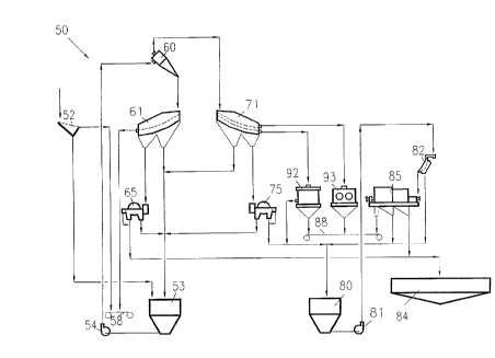
Fig. 2 schem~tir~lly illustrates a coal preparation system 50 in accordance with25 an embodiment of the present invention. Run of mine coal is delivered to a scalping
screen 52, which preferably comprises a conventional banana screen. As used herein
the term "banana screen" means a multi-sloped variable bed depth screen. Such banana
screens are commercially available from comp~ni-os such as Allis Mineral Systems and
Honert Vibration Technic. Oversize pieces which do not pass through the scalping30 screen 52 are delivered to a refuse conveyor 58. The oversize refuse is typically
greater than about 4 inches in diameter. Particles which pass through the scalping
screen 52 are delivered to a heavy media cyclone sump 53 where they are mixed with
a slurry comprising water and magnetizable particles such as magnetite. A pump 54
CA 022~2690 1998-10-27
W O97/41194 PCTrUS97/07095
- 6-
is used transport the aqueous particle mixture from the heavy media cyclone sump 53
to a hydrocyclone 60 which sep~ates the particles into a high specific gravity fraction
comprising refuse particles and a low specific gravity fraction comprising clean coal.
The specific gravity of the fractions can vary ~epen-ling on the type of coal being
S processed and the final quality desired. For most operations, the cut-off between the
high and low specific gravity fractions is from about 1.35 to about 1.8. The high
specific gravity fraction passes through the apex aperture of the hydrocyclone 60, while
the low specific gravity fraction passes through the overflow aperture of the
hydrocyclone 60.
The hydrocyclone 60 plefeldbly has a relatively large ~ meter, e.g., from
about 0.8 to about 1.2 meters. The axial length of the hydrocyclone 60iS preferably
extended to provide a cylindrical section in the area of the input feed passage which
is connected to the tapered conical section. The axial length of the cylindrical section
is p~eft;l~bly greater than about 4 times the diameter of the largest particle being fed
15 to the hydrocyclone. In addition, the hydrocyclone 60 preferably includes an extended
vortex finder which extends axially from the wider end of the hydrocyclone towards
the apex. The extended length of the cylindrical section increases particle retention
time in the hydrocyclone, which allows the separation of lower and higher gravity
fractions over the full range of particle sizes introduced into the hydrocyclone. This
20 allows the hydrocyclone 60 to process relatively large particle sizes of up to 3 or
4 inches or more.
The high specific gravity fraction which exits the apex aperture of the
hydrocyclone 60 is delivered to a drain portion of a refuse drain and rinse screen 61.
The refuse drain and rinse screen 61 preferably col,.p,ises a single deck vibrating
25 screen, most preferably a banana screen. The liquid portion passing through the drain
portion of the refuse drain and rinse screen 61 flows to the heavy media cyclonesump 53 for recirculation to the hydrocyclone 60. The rern~ining portion travels to a
separator portion of the refuse drain and rinse screen 61. Typically, particles having
sizes greater than about 0.25 to about 2mm, and more typically from about 0.5 to30 about lmm are retained on the screen 61. Particles which do not pass through the
refuse drain and rinse screen 61 are delivered to the refuse conveyor 58. The material
comprising fine refuse particles, water and magnetite particles which passes through
the refuse drain and rinse screen 61 is delivered to a first magnetic separator 65. The
......
CA 022~2690 1998-10-27
W O 97/411g4 PCT~US97/07095
-7-
first m~gne~ic se?a,d~or 65 is preferably as desc,il~ed in U.S. Patent No. 4,921,597.
The m~gne~i7~hle particles which are removed by the first magnetic separator 65 are
delivered to the heavy media cyclone sump 53. Upon sepa,aLion of the m~gneti7~hle
particles, the l~..,ainillg liquid fraction is discharged from the first magnetic
ae?~dtor 65 to a thickener 84.
The low specific gravity fraction which exits the overflow aperture of the
hydrocyclone 60 is delivered to a drain portion of a clean coal drain and rinse
screen 71. The clean coal drain and rinse screen 71 preferably comprises a double
deck vibrating screen, most preferably a banana screen. The liquid fraction which
passes through the clean coal drain and rinse screen 71 flows to the heavy mediacyclone sump 53. The remqining portion travels to a separator portion of the clean
coal drain and rinse screen 71 which preferably includes an upper screen and a lower
screen. The clean coal drain and rinse screen 71 separates the low specific gravity
fraction into a small particle-size clean coal fraction and a large particle-size clean coal
fraction. Oversize particles which do not pass through the upper level of the clean coal
drain and rinse screen 71 are delivered to a conventional crusher 93, which
comminutes the oversize clean coal particles to the desired size. The comminutedclean coal particles are then dischal~ed from the crusher 93 onto a clean coal
conveyor 88. Particles which pass through the upper portion but which do not pass
through the lower portion of the clean coal drain and rinse screen 71 are delivered to
a commercially available centrifugal dryer 92 to reduce the water content of the clean
coal. In typical operations these particles will have a minimum particle size of from
about 0.25 to about 2 mm, more typically from about 0.5 to about 1 mm. The driedclean coal is then discharged from the centrifugal dryer 92 onto the clean coal
conveyor 88.
The small particle-size clean coal fraction which passes through both levels of
the clean coal drain and rinse screen 71 is delivered to a second magnetic separator 75.
This fraction typically has a maximum particle size of from about 0.25 to a~out 2mm,
more typically from about 0.5 to about Imm. The second magnetic separator 75 is
p,ere,dbly as described in U.S. Patent No. 4,921,597. Magnetizable particles which
are removed from the water and small particle-size clean coal fraction are delivered
from the second magnetic separator 75 to the heavy media cyclone sump 53. The
remaining small particle-size clean coal fraction is then discharged from the second
CA 022~2690 1998-10-27
W O 97/41194 PCTrUS97tO709S
-8-
m~gnetic se~dtor 75 to a clean coal tailings sump 80. A pump 81 is used to deliver
the small particle-size clean coal fraction to a conventional sieve bend 82 col.-plising
a screen with radially spaced openings. The portion which passes through the sieve
bend 82 travels back to the clean coal tailings sump 80 for recirculation. The
S remainder of the material which does not pass through the sieve bend 82 is delivered
to a commercially available screen bowl centrifugal dryer 85. In a first drying stage,
liquid is discharged from the dryer 85 to the thickener 84. In a second drying stage,
water and entrained clean coal pa~ticles are discharged from the dryer 85 to the clean
coal tailing sump 80 for recirculation to the sieve bend 82. In a final stage, the dried
small particle-size clean coal fraction is discharged from the dryer 85 to the clean coal
conveyor 88.
Fig. 3 schçm~ically illustrates a coal preparation system 50 in accordance with
an embodiment of the present invention similar to that shown in Fig. 2, with certain
variations. In the embodiment of Fig. 3, the liquid fraction which passes through the
sieve bend 82 is delivered directly to the thickener 84 instead of the clean coal tailings
sump 80. Thus, once the small particle-size clean coal fraction is passed through the
sieve bend 82, it is not recirculated through the tailings sump 80, but is rather
discarded to the thickener 84.
Fig. 4 schematically illustrates a coal preparation system 50 in accordance withanother embodiment of the present invention. In this embodiment, a system similar to
that shown in Figs. 2 and 3 is combined with certain features of the system of Fig. I,
which are generally shown with broken lines. In addition to the sc~lping screen 52,
the run of mine coal is first delivered to a clçcliming screen 11 to remove fines, e.g.,
particle sizes of less than about lmm. Overflow from the dçsliming screen 11 travels
to the scalping screen 52. As with the embodiments of Figs. 2 and 3, the scalping
screen 52 sepalal~s oversize refuse pieces and allows undersize particles to pass
through the screen. The particles which pass through the scalping screen 52 may then
be treated in the same manner as the embodiments of Figs. 2 and 3. In addition, the
fine particles passing through the desliming screen 11 as shown by the broken lines of
Fig. 4 are delivered to a sizing hydrocyclone 20 via a tank 13, in a manner similar to
that shown in Fig. 1. The portion which passes through the overflow aperture of the
sizing hydrocyclone 20 flows to the thickener 84 or to flotation. The portion
discharged from the apex aperture of the sizing hydrocyclone 20 travels to spirals 21
CA 022~2690 1998-10-27
W O 97/41194 PCTrUS97/07095
g
and then to either the sieve bend 82 or the dewatering screen 23. The fraction which
does not pass through the sieve bend 82 is delivered to the dryer 85 along with the
overflow from the clean coal tailings sump 80. The dried clean coal fraction is then
discha,~ ed from the dryer 85 to the clean coal conveyor 88.
S Fig. S schern~tic~lly illustrates a further embodiment of the present invention
similar to that shown in Fig. 4, with certain variations. In the embodiment of Fig. 5,
the second m~n~tic separator 75 does not discharge to a clean coal tailings sump 80
as shown in Fig. 4, but rather discharges to the tank 13. In this manner, after the
m~gneti7~ble particles are removed from the small particle-size clean coal fraction, the
fraction is delivered to the sizing hydrocyclone 20 and may pass through the apex
opening thereof for further processing by the spirals 21.
The method and apparatus of the present invention advantageously use high-
capacity, high-efficiency single units of equipment which rely on each other's
pe.rol..,allce to achieve highly improved overall process capacity and efficiency. The
15 use of large (li~meter cyclones capable of processing large particles of up to about 4
inches eliminates the necessity of a separate circuit for coarse particles as is typically
used in conventional coal processing plants. The use of high efficiency drain and rinse
screens allows a single screening unit to perform the function of multiple screens
required in prior art plants. The use of separate high capacity, high efficiency20 magnetic separators for the refuse and clean coal circuits permits the recovery of
uncont~min~tPd magnetite in a single pass through, and allows segrated clean coal to
be recovered directly from the hydrocyclone as a final product without recirculation
through the system. In addition, the present system reduces the requirements forpumps, piping, fixtures, and the like, which reduces costs and maintenance in
25 co-"pa,ison with conventional plants.
While specific embodiments of the present invention have been described in
detail, it will be appreciated by those skilled in the art that various modifications and
alternatives to those details could be developed in light of the overall teachings of the
disclosure. Accordingly, the particular arrangements disclosed are meant to be
30 illustrative only and not limiting as to the scope of invention which is to be given the
full breadth of the claims appended and any and all equivalents thereof.
... . .