Note: Descriptions are shown in the official language in which they were submitted.
CA 02252774 1998-10-27
WO 97/45947 PCT/FI97/00328
1
SWITCHED-MODE POWER SUPPLY ARRANGEMENT
BACKGROUND OF THE INVENTION
The present invention relates to a switched-mode power supply
arrangement comprising at least two switched-mode-type power supplies that
are provided with a transformer and that have outputs connected in parallel.
As described above, the invention relates specifically to a switched-
mode power supply arrangement comprising at least two parallel-connected
switched-mode-type power supplies. Supervision of output voltages of such
switched-mode-type power supplies to be connected in parallel typically
requires the use of a so-called separation diode. However, such a separation
diode considerably decreases the efficiency of the power supply, especially in
power supplies having a low output voltage (e.g. 2.1 V and 3.3 V) used more
and more commonly.
The object of the present invention is to provide a switched-mode
power supply arrangement where single switched-mode-type power supplies
can be connected in parallel without the need for a separation diode at the
output of each power supply. Another object of the invention is to provide a
switched-mode power supply arrangement which enables controlling, with very
simple means, the operation of each parallel-connected switched-mode power
supply and giving an alarm concerning different failure modes.
SUMMARY OF THE INVENTION
The aforementioned objects are achieved by means of a switched-
mode power supply arrangement according to the invention, characterized in
that each parallel-connected switched-mode power supply comprises means
for generating in a reference voltage output a voltage that is proportional to
the
pulse duty factor of the secondary voltage of the transformer, that the
reference voltage outputs of each switched-mode power supply to be
connected in parallel are coupled together, and that each parallel-connected
switched-mode power supply also comprises means for detecting a current
that flows through the reference voltage output, and for generating a
correction
voltage proportional to this current in order to correct the output voltage of
the
switched-mode power supply.
In the arrangement according to the invention, a voltage that is
proportional to the pulse duty factor of each switched-mode power supply is
compared to the corresponding average voltage of the other parallel
CA 02252774 1998-10-27
WO 97/45947 PCT/FI9?/00328
2
connected switched-mode power supplies, and the obtained offset voltage is
used to correct the output voltage of the switched-mode power supply in such
a way that even with a small load the pulse duty factor remains equal with the
other switched-mode power supplies, so that all parallel-connected switched-
mode power supplies remain in operation also with a small load.
Each switched-mode power supply to be connected in parallel
preferably also comprises an overvoltage comparator for comparing the output
voltage of the switched-mode power supply to a predetermined nominal
voltage and means for disconnecting the correction voltage of the output
voltage when the output voltage exceeds the nominal voltage. If the output
voltage of a switched-mode power supply exceeds its normal or nominal level,
the output voltage being the same for each parallel-connected switched-mode
power supply due to the parallel connection, the overvoltage comparator
disconnects the correction of the output voltage and simultaneously the
upkeep; in other words the control circuits of the non-faulty switched-mode
power supplies terminate their operation and the only power supply still in
operation is the faulty one that causes the overvoltage.
It is also preferable that each switched-mode power supply to be
connected in parallel also comprises a voltage comparator for comparing the
reference voltage to a predetermined minimum voltage in order to detect the
operation of the switched-mode power supply, and means for combining the
operation data and the overvoltage data and for giving an alarm, depending on
the combination of the aforementioned data. When data indicating the
operation of the switched-mode power supply is provided on the basis of the
reference voltage by means of the comparator and when this data is combined
with the overvoltage data obtained from the overvoltage comparator, it is
possible to generate overvoltage alarm data to a switched-mode power supply
if there is an overvoltage and if the switched-mode power supply in question
is
in operation. On the other hand, if the switched-mode power supply is not in
operation and if there would seem to be no overvoltage, a fault alarm is given
concerning the switched-mode power supply.
It is also preferable that each switched-mode power supply to be
connected in parallel also comprises an undervoltage comparator for
comparing the output voltage of the switched-mode power supply to a
predetermined nominal voltage and means for giving an alarm when the
output voltage falls below the nominal voltage.
CA 02252774 1998-10-27
WO 97/45947 PCTlFI97/00328
3
BRIEF DESCRIPTION OF THE DRAWING
In the following, a switched-mode power supply arrangement
according to the invention will be described in greater detail with reference
to
the accompanying drawing, which is a functional block diagram illustrating one
switched-mode power supply to be connected in parallel in the switched-mode
power supply arrangement according to the invention.
DESCRIPTION OF THE PREFERRED EMBODIMENT
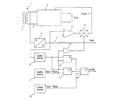
In the figure, reference numeral 1 denotes a switched-mode power
supply that is provided with a transformer 2 and that may be a forward-type
switched-mode power supply, for example. The other components contained
in the switched-mode power supply 1, excluding the transformer 2, are
represented by a block that is denoted by reference numeral 3 and that
provides an output voltage Uout. Such a switched-mode power supply of the
forward-type, for example, is fully conventional in the art and therefore its
operation will not be described in greater detail in this connection.
According to the invention, the pulse duty factor of the secondary
voltage of the transformer 2 in the switched-mode power supply 1 is monitored
by converting it with a D/U converter represented by a block 4 into a voltage
Uref that is proportional to the pulse duty factor. The pulse duty factor of
the
switched-mode power supply refers to the ratio between the pulse width and
the period. The pulse duty factor is therefore always between 0 and 1, since
it
describes the proportion of the pulse width from the total duration of the
period. It is this pulse duty factor that is used to adjust the output voltage
of
the switched-mode power supply, and this average output voltage is naturally
the higher the greater the pulse duty factor, i.e. the longer the proportion
the
pulse width covers from the total duration of the period.
The voltage Uref that is generated with the block 4 and that is
proportional to the pulse duty factor is significant in the arrangement
according
to the invention. By coupling the reference voltages of the parallel-connected
switched-mode power supplies directly to each other, it is possible to easily
generate a control voltage for each switched-mode power supply, so that their
output voltages Uout can be adjusted to the same level. If there is a current
flow through the output Uref, it means that the parallel-connected switched-
mode power supplies have had different pulse duty factors and therefore the
voltages Uref proportional to these pulse duty factors have been mutually
CA 02252774 1998-10-27
WO 97/45947 PCT/FI97/00328
4
different. By monitoring this current by means of an amplifier 6 for example
over a resistor 5 that is connected in series with the reference voltage
output
of the block 4, it is possible to generate a correction voltage Ucor that is
proportional to this current. In the coupling shown in the drawing, this
voltage
Ucor is connected to the block 3 where it is used to adjust the level of the
output voltage Uout of the switched-mode power supply such that the current
flow through the resistor 5 can be made as small as possible.
The switched-mode power supply arrangement according to the
invention can be supplemented further in a simple manner by utilizing the
voltage Uref that is proportional to the pulse duty factor. If this reference
voltage Uref is very low or zero, it means that the pulse duty factor is very
low
and the switched-mode power supply is therefore not in operation. This
comparison is performed with a comparator 9 where the voltage Uref is
compared to a low predetermined voltage level that can be called for example
a minimum voltage. When the voltage falls below this minimum voltage, the
switched-mode power supply is considered to have stopped operating and this
data is forwarded to blocks 10 and 11 where it is combined with the
overvoltage data from a comparator 7. This comparator 7 is arranged to
compare the output voltage Uout of the switched-mode power supply to a
predetermined nominal voltage Unom. If the comparator 7 detects that the
output voltage of the switched-mode power supply exceeds the nominal value
Unom, this output data of the comparator 7 (e.g. value 1 ) is used to control
an
inverting amplifier 14 the output of which (e.g. value 0) in turn controls an
analog switch 8 that disconnects the supply of the correction voltage Ucor to
the switched-mode power supply 1. Since the overvoltage comparator 7 has
disconnected, by means of the switch 8, the correction of the output voltage
from the switched-mode power supply and simultaneously the upkeep, it
means that the control circuit of each parallel and operating switched-mode
power supply terminates, as a result, the operation of the power supply and
the only switched-mode power supply in operation is the faulty one that
causes the overvoltage.
Since the comparator 9 provides data about the operation of the
switched-mode power supply and, on the other hand, since the comparator 7
provides data about the ovenroltage mode, it is possible to give an
overvoltage
alarm concerning the switched-mode power supply in question by combining
the aforementioned data in the block 10 which is a logic AND circuit. On the
CA 02252774 1998-10-27
WO 97/45947 PCT/FI97/00328
other hand, if the comparator 9 provides data that the switched-mode power
supply is not in operation, but on the other hand, there is no overvoltage
data
from the comparator 7, this data of the logic level 0 can be combined in the
block 11 which is a logic NOR circuit, and it is possible to provide data
5 indicating that the switched-mode power supply in question is faulty.
The switched-mode power supply arrangement according to the
invention further comprises an undervoltage comparator 13 where the output
voltage Uout of the power supply is compared to the aforementioned
predetermined nominal voltage Unom. If such an undervoltage state is
detected, a direct alarm is given via a block 12.
By means of the blocks 7 and 9 to 13 it is possible to generate
different alarm data in different modes of operation, as described above. The
aforementioned different alarm modes and their operating conditions are also
shown in the following table.
Uout < Unom Uout = Unom Uout > Unom
power supply ALARM IN ORDER ALARM
in
operation
power supply ALARM ALARM IN ORDER
stopped
As described above, it is possible to eliminate, with relatively simple
arrangements, the separation diode that was previously required at the output
of parallel-connected switched-mode-type power supplies and that decreased
their efficiency. Further, with the arrangement according to the invention the
output voltages of the switched-mode power supplies to be connected in
parallel can be adjusted in such a way that all the power supplies remain in
operation also without a load. In this manner, the operation of the power
supplies can also be monitored in case of a very small or zero load.
The switched-mode power supply arrangement according to the
invention and the advantages it provides are described above by means of
only one illustrative embodiment and it should be understood that it can be
modified in some ways, especially as regards the detailed structure of the
means providing the different functions, without deviating from the scope of
protection defined in the appended claims, however.