Note: Descriptions are shown in the official language in which they were submitted.
CA 02252841 1998-10-21
WO 98/28506 PCT/US97/23534
COMPOSITE FILLED HOLLOW STRUCTURE
BACKGROUND OF THE INVENTION
This invention deals generally with stock material, and more
specifically with filled hollow structures such as light poles, fence posts
and
pilings constructed of plastic or fiberglass.
The benefits of plastic and fiberglass for articles which are used where
they are subject to corrosion are generally well recognized. Structures using
such materials are light weight, strong and attractive. They can be made with
color integrated into the material so that they do not need frequent painting
during their use, and possibly their greatest asset is the inherent chemical
resistance of the material. A fiberglass or plastic structure such as a fence
post can be expected to last as long as anyone wants it to, even in the most
severe environment, with no sign of deterioration, and it will not require any
maintenance.
Unfortunately, the major limitation on the availability of such pole
type fiberglass or plastic structures has been the cost and difficulty
involved in
their manufacture. One typical method of fiberglass construction is the
forming of the fiberglass into a specific shape by wrapping multiple layers of
fiberglass fabric on the outside of a core and impregnating the fabric with
resin or epoxy, however such manufacturing methods are very expensive
because they involve a great deal of hand labor.
Another approach, particularly to the construction of cylindrical
structures, is to use preformed fiberglass or plastic pipe. However, such pole
CA 02252841 1998-10-21
WO 98/28506 PCT/US97/23534
2
structures are not strong enough for most applications unless the pipe is very
thick or the structure includes wood or metal reinforcing, and both of these
approaches raise the cost of fiberglass and plastic poles so that they are not
competitive with conventional metal poles.
One approach to reinforcing fiberglass or plastic pipe so it can be used
as a structural member has been the use of fillers which are poured into the
inside of the pipe, and then harden into a core. Fillers have been suggested
which include wood with an adhesive binder (U.S. Patent 4,602,765 by
Loper) and rigid foam or concrete (U.S. Patent 3,957,250 by Murphy), but
these approaches do not furnish strength comparable to metal poles.
SUMMARY OF THE INVENTION
The present invention improves upon the technique of filling the
interior of a hollow member to reinforce it by using a particular filler
material
mixture which produces a structure of greater strength by creating a stronger
core and a superior bond to the exterior member. This is accomplished by
selecting a material which normally expands while it is hardening, but is
contained by the tubular form, thereby producing a strong core with a
stressed set and a force fit bond with the external member.
In the preferred embodiment of the invention, the material used for the
core is a Portland-type cement based structural material. Such material would
expand as it is setting up except that it is restrained from expanding by the
CA 02252841 1998-10-21
WO 98/28506 PCT/US97/23534
external member. The external member selected for the outside of the pole is
selected to have a structural strength which is greater than the expansion
force of the core structural material. Therefore, as the core material
hardens,
it forms a plug with a permanent positive stress and a higher than usual
density within the external member, and this plug is locked tightly within and
virtually bonded to the external member.
In effect, a compression stressed core member is formed within and
integrated with the external member, and this gives the filled hollow
structure
greater strength than would result from a core material which does not
expand upon hardening, because a core made of such a non-expanding
material could shrink and slide within the external member at the boundary
between the external member and the core. To derive the full benefit of the
filled hollow structure, the core material must also have great enough
structural strength to add significantly to the strength of the finished
structure.
An additional benefit of the structure of the preferred embodiment is
that the external member protects the core material from any environmental
factors which might otherwise cause the core material to deteriorate with
exposure.
Two other techniques are also used to increase the strength of the
filled hollow structure. One, which is available only for structures which
include fiberglass in the external hollow member, involves the specific
orientation of the rovings of the fiberglass used in the external ,member.
When
the external member is constructed so that the fiberglass rovings in it are
longitudinally oriented with respect to the axis of the external member, it
has
CA 02252841 1998-10-21
WO 98/28506 PCT/US97/23534
4
greater resistance to bending than does a structure in which the rovings are
aligned perpendicular to the axis. This increase in strength is not sufficient
to
permit the use of an external member without a strengthened core.
Another benefit can be secured from the selection of a proper veil
coating on the outside surface of the external member. Such veil coatings are
often used to protect fiberglass reinforced products from deterioration caused
by exposure to ultraviolet rays.
A final additional coating can also be added to the pole structure of
the present invention to add particular surface finishes and additional
ultraviolet protection.
Another aspect of the invention is to provide a filled structure
including a fiber reinforced resinous hollow structure having a tensile
strength
of at least 30,000 psi and an inside surface forming a boundary which
encloses a space. A hard core is provided within the space enclosed by the
hollow structure. The hard core has a density of at least 35 pounds per cubic
foot and a compressive strength of at least 1500 psi. The hard core is formed
from a mixture of particulate, cementitious material and liquid. The filled
structure is constructed and arranged such that the hard core is locked to the
inside surface of the hollow structure. The locking is provided by a
mechanical lock, such as roughening an inside surface or by the molding of
ridges into the inside surface of the hollow structure, where the core
envelopes the ridges and/or fills the valleys, or by a chemical lock, such as
providing an adhesive on the inside surface of the hollow structure.
CA 02252841 1998-10-21
WO 98/28506 PCT/US97/23534
The hard core may expand its volume as it hardens, with the
expansion of the mixture being restrained by the hollow structure and the hard
core exerting a force against the inside surface of the hollow structure.
The present invention therefore furnishes a highly desirable
improvement for fiberglass and plastic filled hollow structures which makes
them practical to use for such common and cost sensitive applications as light
poles, fence posts and pilings, since they can now be competitive with metal
poles and other traditional materials.
BRIEF DESCRIPTION OF THE DRAWINGS
FIG. I is an end view across the axis of an embodiment of the
invention.
FIG. 2 is an end view across the axis of another embodiment of the
invention.
FIG. 3 is an end view across the axis of yet another embodiment of
the invention.
FIG. 4a is a partial end view of concave ridges formed in a pipe of the
mventlon.
FIG. 4b is a partial end view of convex ridges formed in a pipe of the
invention.
CA 02252841 1998-10-21
WO 98/28506 PCT/US97123534
6
DETAILED DESCRIPTION OF THE INVENTION
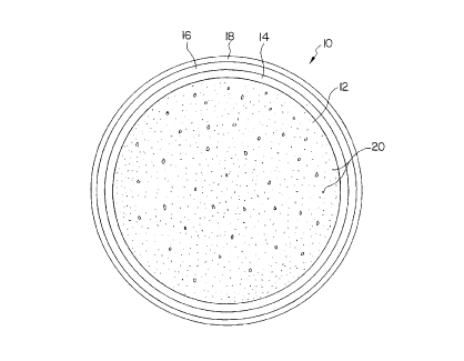
FIG. 1 shows an end view across the axis of pole 10 of the preferred
embodiment. Pole 10 is preferably formed of four distinct materials, one of
which, core 12, takes on a particular significance because of the manner in
which it is formed. Core 12 is encased within pipe 14 which is covered by
veil 16, on top of which is placed protective surface coating 18. Each of the
four parts of composite pole structure 10 adds a particular characteristic to
the pole structure, and together they furnish a pole of superior strength and
durability which can be produced economically. In the broadest aspect of the
invention, the veil 16 and coating 18 need not be provided.
The construction of pole 10 is essentially based upon the filling of pipe
14 with core 12, but core 12 has unique properties which produce a non-
metallic pole with strength equivalent to that of steel poles. Core 12 is a
Portland cement based product with admixtures which enables the mixture to
expand as it hardens, or at least limit shrinkage of the mixture as it
hardens.
In the preferred embodiment, it is important that the core material
normally expand in order that it have a permanent positive stress and produce
a force fit with exterior pipe 14. It is also vital that the hardened core
have
significant strength, which is best indicated by a compressive strength rating
of at least 1500 psi, so that it adds significant strength to the structure
and
does not act to merely fill the interior space of the pipe. The load/force
developed as the core 14 hardens must, however, be less than.the structural
strength of pipe 14 in order to prevent the forces produced by the attempted
expansion during hardening of core 12 from distorting and/or substantially
CA 02252841 1998-10-21
WO 98/28506 PCT/LTS97/23534
7
weakening pipe 14 as it restrains the expansion of core 12.
In the preferred embodiment, cylindrical pipe 14 has a two inch outer
diameter with .030 inch wall thickness up to a ninety-six inch diameter with
at
least .500 inch wall thickness. The pipe 14 is constructed with a standard
polyester, epoxy or vinyl ester resin base, reinforced with fibrous roving,
chop, or woven mat throughout its entire thickness. Such a material has a
tensile strength of at least 30,000 psi. Added bending strength can be
attained
if the significant portion of the fibrous roving are oriented to be at an
angle of
at least 45 degrees to the axis of the pole. The fibrous roving in the
illustrated embodiment is fiberglass. It can be appreciated that other fibrous
rovings such as carbon, etc. may be used.
As with all fiberglass and resin structures, color pigments may be added
during manufacture of pipe 14 to produce consistent color throughout the
entire pipe.
It is also advantageous to produce veil 16 on the exterior surface of
pipe 14 when it is being manufactured. Veil 16 is a layer of polyester or
other
material cloth impregnated with resin. The production of such a veil is well
understood by those skilled in the art of fiberglass construction. Veil 16
protects the fiberglass against ultraviolet radiation, provides a moisture
barrier, protects against blooming of the surface fibers of the fiberglass and
also adds strength to pole 10.
The core 12 is composed primarily of a mixture of stone, sand, water,
and Portland-type cement. In the preferred embodiment, the specific material
used is Type I Portland-type cement as manufactured by the Lehigh Cement
CA 02252841 2002-05-28
~ WO 98/28506 PCT/US97/23534
8
Co. The stone component could be solid limestone, as commonly found at
may local quarries, or lightweight type aggregate as produced, for example,
by Solite Corp. The sand component is clean washed and specifically graded
round silica material as is available from many local sand quarries. Normal
potable water is used and other cementitious products may be employed to
promote expansion or at least limit shrinkage of the core upon hardening. For
example, Expansion additives such as INTRAPLAST N manufactured by
Sika (plastic state expansion), or CONEX, as manufactured by IAI Cement
Co. (early hardened state expansion) may be used in the core. Alternatively, a
standard expansion agent such as alumina hydrate may be employed in the
core, or the core may comprise Type K cement.
When hardened this formula yields a compressive strength of 1500 -
15,000 psi. Moreover, this particular formula normally expands about 0.1-10
percent upon hardening, except that it is restrained by the hollow tube 14 and
therefore provides an exceptionally strong force fit with hollow tube or pipe
14. The density of such a core is at least 35 pounds per cubic foot. The
mixture may be formulated such that shrinkage is limited or made to be
generally negligible, unlike shrinkage which may occur in normal cement-type
products.
Protective coating 18 may also be added to pole 10, for the purpose
of enhancing ultraviolet protection and corrosion resistance and to produce a
smooth surface. The coating 18 is applied during the manufacture of the pipe
and is at least .001 inch thick. Protective coating 18 is clear, can be made
with or without pigments, and includes specific ultraviolet absorbers and/or
shields. An example of such a coating could be 'Amerishield" as
manufactured by Ameron Corp. or '"Tufcote" as manufactured by DuPont.
* Trade-mark
CA 02252841 1998-10-21
WO 98/28506 PCT/US97/23534
9
The composite pole of the present invention can furnish bending
strength equal to or greater than Schedule 40 steel pipe {ASTM F-1083) of
the same diameter, and its inherent corrosion resistance is far superior to
that
of steel. Moreover, the present invention actually furnishes a pole which will
flex more than twice as far as steel and return to its original shape without
failure.
FIG. 2 shows another embodiment of a composite pole structure 100
of the invention. As shown, the inner surface 110 of the pipe 140 is
roughened to form a regular or irregular pattern therein. In the illustrated
embodiment, the inner surface 100 includes an irregular pattern defining a
plurality of recesses 112 which increases the surface area contact between the
core 120 and the pipe 140 when the core 120 hardens within in the pipe 140.
Thus, a portion of the core 120 is disposed in the recesses 112 defining a
mechanical lock between the core 120 and the pipe 140. The core 120, pipe
140, veil 160 and coating 180 are otherwise identical to the embodiment of
FIG. 1. Alternatively, as shown in FIGS. 4a and 4b, instead of the recesses,
ridges 112' or 112 can be molded or otherwise formed into the inner surface
110' of the pipe 140'. The ridges may be concave 112' (FIG. 4a) or convex
112' (FIG. 4b) and may be in a regular or an irregular pattern. It can be
appreciated, however, that the core 120 need not be of the type which
expands its volume when it hardens to provide a force fit with the pipe 140,
since the mechanical lock provides the desired locking of the core 120 to the
pipe 140. It can also be appreciated that the core may be of the type in which
shrinkage is limited during hardening thereof.
FIG. 3 shows yet another embodiment of a composite pole structure
CA 02252841 2002-05-28
WO 98/28506 PGT/US97123534
200 of the invention. As shown, an adhesive 250 is coated on the inner
surface 212 of the tube 240 such that when the core 220 hardens it is
chemically locked with respect to the pipe via the adhesive 250. The adhesive
250 is preferably SIKADUR 32~ manufacture by Sika. However, any type
of adhesive suitable for securing the resin pipe.240 to the hardened core may
be employed. The core 220, pipe 240, veil 260 and coating 280 are identical
to the embodimeat of FIG. 1. It can be appreciated, however, that. the core
220 need not be of the type which expands its volume when it hardens to
provide a force fit with the pipe 240, since the chemical lock provides the
desired locking of the core 220 to the pipe 240. It can also be appreciated
that the core may be of the type in which shrinkage is limited during
hardening thereof.
Tests were performed to determine the push-out strength or frictional
resistance of the core material to the inner wall of the composite pole
structure. The total load in pounds required to dislodge the core from the
hollow tube was measured and divided over the unit area and represented in
units of psi. The average frictional resistance of the core made in accordance
with the embodiment of FIG. 1, (no mechanical ar chemical locking of the
core) was measured to be on average 25 psi over the entire inner wall surface
of the pipe. With the addition of an adhesive 250 bonding the core 220 to the
pipe 240 (FIG. 3) the average frictional resistance of the core was determincd
to be approximately 90 psi. Thus, there is a con~esponding miaimum increase
in bending strength of approximately 30% as a result of a better bond
between the core and the pipe which provides for a better transfer of shear
between the stnictural component parts. With both expansion of the core 220
and the use of the adhesive 250 (FIG. 3), failure of the composite structure
is
CA 02252841 1998-10-21
WO 98/28506 PCT/US97/23534
often in the cohesive strength of the core 220 itself. Namely, the cohesive
strength of the bond between the core and pipe can be stronger than the
cohesive strength of the core 220.
Additives 20 may be included in the core of the invention to improve
the composite pole structure. For example, silica fume, an extremely fine
aggregate that fills tiny voids in the core may be added to the core to
improve
the compressive thus, making he composite pole structure even stronger.
Steel, glass or polymer fibers additives mixed into the core could also be
employed. The fibers deter cracking which cause premature failures, provide
higher stiffness, provide higher compressive strength and provide higher
bending strength, all of which enhance the performance of the composite pole
structure.
It is to be understood that the form of this invention as shown is
merely a preferred embodiment. Various changes may be made in the function
and arrangement of parts; equivalent means may be substituted for those
illustrated and described; and certain features may be used independently from
others without departing from the spirit and scope of the invention as defined
In the following claims.
For instance, structures may be produced without either veil 14 or
protective coating 16 when the application does not require ultraviolet
protection. Moreover, the diameter and cross sectional configuration of the
external member may, of course vary, and the particular formula of the core
could be changed as long as the requirements of the claims are retained.
Further, although a generally round cross-sectioned pipe is disclosed, the
CA 02252841 1998-10-21
WO 98/28506 PCT/US97/23534
12
composite structure may be in any shape or closed section, such as, for
example a square, rectangular, oval etc, cross-section.