Note: Descriptions are shown in the official language in which they were submitted.
CA 02253033 1998-11-06
Emanuel D. Fry
HIGH-LOW PRESqITRF F-TFRI~fF'rrr, COMPRFSSC'iR
$ACK ROUND OF THE TNVENTION
The present invention relates generally to hermetic compressor assemblies and,
more
particularly, to compressors that are divided into separate discharge or high
pressure and
suction or low pressure sections.
Hermetic compressors comprise a hermetically sealed housing having a
compressor
mechanism, motor, and various related parts mounted therein. The compressor
mechanism
typically includes a crankcase, also referred to as a cylinder block in rotary
and reciprocating
piston type compressors, which defines at least one compression chamber in
which gaseous
refrigerant is compressed and subsequently discharged into a common discharge
cavity.
Suction gas at low pressure is drawn into the housing of the compressor and is
delivered to
the compressor mechanism where the suction gas is compressed by the
reciprocating piston in
the cylinder and discharged at discharge pressure into a discharge cavity and
ultimately out of
the compressor housing. Gas at suction pressure is maintained separate from
the discharge
gas., Some compressors are referred to as high-side units, in which the
housing is generally at
1 S discharge or high pressure, i.e. discharge gas occupies the space defined
by the housing.
Other compressors are referred to as low-side units, in which the housing is
generally at
suction or low pressure, i.e. suction gas occupies the space defined by the
housing. Although
high side machines offer a more attractive environment from the standpoint of
flow of
lubricating oil throughout the compressor, a problem associated with high side
machines is
that with the motor surrounded by high temperature discharge gas, the
operating efficiency of
the motor and the compressor are lessened.
::ODMA\PCDOCS\FWDOCS11381\I
CA 02253033 1998-11-06
SUMMARY OF THE INVENTION
The present invention provides an improved hermetic compressor arrangement
wherein an internal baffle system provides an improved separation of low and
high pressure
chambers or sections within the compressor housing. In the compressor of the
present
invention, a valve plate and piston combination divides the compressor into a
low pressure
area and a high pressure area. The motor, oil sump, and lubrication system are
located in the
low pressure area and are surrounded by Iow suction pressure fluid. The
suction pressure
fluid is at a lower temperature than the high pressure discharge fluid. By
placing the motor,
sump, and lubrication system in the low suction pressure area, the temperature
of the
lubricating oil, and therefore the temperature of the bearings lubricated
therewith, and the
operating temperature of the motor are reduced, while the high temperature
portion of the
compressor, cylinder head, valve plate, etc., is in the discharge portion of
the system. This
provides a means for allowing the heat of compression to be dissipated to the
condenser side
of the system as opposed to the evaporator or low side of the system. This
results in
prolonged bearing life and optimized motor reliability and performance, while
optimizing the
thermal efficiency of the compressor.
Two principal factors result in enhanced oil flow through the compressor; 1)
centrifugal force generated by fan-like blades provided at the top of the
rotor causes the oil to
be flung outward against the motor windings to be returned to the oil sump in
the bottom of
the housing, and 2) the combination of a seal cup at the upper end of the
crankshaft, and a
secondary bore formed in the upper end of the crankshaft and in communication
with the
yoke cavity. The seal cup and crankshaft form an area at suction pressure.
This combination
operates to aid in drawing oil up through the oil passage due to a natural
pressure drop that
occurs from the oil passage to the yoke cavity from the Iower housing suction.
The pressure
::ODMA\PCDOCS\FWDOCS1\381\I 2
CA 02253033 1998-11-06
drop between the oil passage and the yoke cavity is primarily a result of the
reciprocating
action of the pistons which draw suction fluid from the yoke cavity.
Centrifugal force directs
lubricating oil outward from the oil passage into lateral radial passages
formed in the
crankshaft to lubricate bearings along the length of the crankshaft. An
orifice device, such as
a bolt or plug with a hollow bore therethrough, is placed in the secondary
bore to act as a dam
to prevent oil slung against the inner surface of the seal cup from traveling
into the secondary
bore and into the yoke cavity, unless the area formed by the seal cap and the
upper surface of
the crankshaft becomes flooded with oil. Lubricating oil slung against the
inner surface of
the seal cup travels downward along the rotational bearing provided at the
upper end of the
crankshaft.
During compressor operation, refrigerant travels from the low suction pressure
area
surrounding the motor to the low pressure area in the yoke cavity via the
annular space
provided between the muffler or baffle plate and the crankcase shaft hub. Fan
blade-like
protuberances, located on the top of the rotor facing the muffler plate,
create a centrifugal
effect that acts upon liquid refrigerant and oil mixture which may occur
during liquid
flooding conditions forcing it outward between a gap formed between the stator
and the
muffler plate and ultimately into the area within the lower housing. This
enhances
compressor operation and reliability by reducing liquid slugging during
abnormal flooding
conditions and prompts high circulation rates..
The high/low pressure compressor of the present invention provides an
environment
in which the motor and lubrication system are operating at system low or
suction pressure
condition, which provides for both a cool efficient motor and cool operating
lubrication
system. The high temperature portion of the compressor, the compressor
mechanism, is in
the discharge portion of the system. This provides for a means of allowing the
heat of
::ODMA\PCDOCS\FWDOCS i\381\I
CA 02253033 2003-07-22
compression to be dissipated to the condenser side of the system as opposed to
the
evaporator or low side of the system.
In addition, the present invention involves providing an annular acoustic
insulation
device intermediate the crankcase and an annular welding ring, which is now to
be placed at
intersection of the lower and upper housing members to hermetically seal same
together.
The acoustic insulator may be mechanically or otherwise bonded or secured to
the crankcase
and the annular welding flange, and forms a part of the high to low pressure
seal. By way of
example and not limitation, accepta.blc bonding methods include ultrasonic
welding, solvent
welding, acrylic adhesive, and hot metal bonding. The acoustic insulator may
be made from
such materials as neoprene-based elastomers, butylene-type elastomers, silicon-
based
elastomers, dense fiber type elastomers, etc. During normal operation the
insulator prevents
the crankcase from engaging the welding ring and deflects so as to absorb
loads associated
with compressor operation. The insulator isolates vibrations from the
crankcase and reduces
the communication of same to the housing. Should the insulator experience an
excessive
load, the crankcase and welding flange may touch, however sufficient clearance
is provided
between the insulator and the inner surface of the housing to prevent the
insulator from
engaging the housing and rubbing thereagainst. The elastomer-based insulator
has memory
and essentially returns to its normal, pre-load shape once a load dissipates.
Accordingly, in one aspect of the present invention, there is provided a
hermetic
compressor comprising:
a hermetically sealed housing having an oil sump therein;
a reciprocating compressor unit disposed in said housing and adapted to
receive and
compress refrigerant fluid at a suction pressure and discharge compressed
refrigerant fluid at
a discharge pressure;
a motor having a stator and a rotor, said rotor rotatably connected to a
crankshaft
drivingly connected to said reciprocating compressor unit;
4
CA 02253033 2004-03-23
a lubrication system including an oil pump adapted to communicate oil from
said oil
sump to at least one oil outlet, said at least one oil outlet adapted to
deliver lubricating oil to
said reciprocating compressor unit;
a portion of said reciprocating compressor unit dividing said housing into a
high
pressure area, essentially at discharge pressure, and a low pressure area,
essentially at suction
pressure, said motor and said lubrication system disposed in said low pressure
area, and said
compressor unit discharging compressed refrigerant fluid into said high
pressure area.
According to another aspect of the present invention, there is provided a
hermetic
compressor for use in one of a refrigeration system and an air-conditioning
system having a
condenser and an evaporator, said compressor comprising:
a hermetically sealed housing having an oil sump therein;
a reciprocating compressor unit disposed in said housing and adapted to
receive and
compress refrigerant fluid from the evaporator at a suction pressure and
discharge
compressed refrigerant fluid at a discharge pressure to the condenser;
a motor having a stator and a rotor, said rotor rotatably connected to a
crankshaft
drivingly connected to said reciprocating compressor unit; and
a lubrication system including an oil pump adapted to communicate oil from
said
sump to at least one oil outlet, said at least one oil outlet adapted to
deliver lubricating oil to
said reciprocating compressor unit;
wherein said reciprocating compressor unit divides said housing into a high
pressure
area, essentially at discharge pressure, and a low pressure area, essentially
at suction
pressure, said motor and said lubrication system disposed in said low pressure
area, and said
compressor unit discharging compressed refrigerant fluid into said high
pressure area, the
evaporator coupled to said low pressure area and the condenser coupled to said
high pressure
area.
5
CA 02253033 2005-O1-11
According to yet another aspect of the present invention, there is provided a
hermetic
compressor comprising:
a hermetically sealed housing having an oil sump therein and being divided
into a
high pressure area and a low pressure area;
a reciprocating compressor unit disposed in said housing and adapted to
receive and
compress refrigerant fluid at a suction pressure and discharge compressed
refrigerant fluid at
a discharge pressure into said high pressure area and wherein a portion of
said reciprocating
compressor unit divides said housing into said high pressure area and said low
pressure area;
a motor having a stator and a rotor, said rotor rotatably connected to a
crankshaft
drivingly connected to said compressor unit; and
a lubrication system including an oil pump adapted to communicate oil from
said oil
sump to at least one oil outlet, said at least one oil outlet adapted to
deliver lubricating oil to
said compressor unit;
said motor disposed in said low pressure area and said lubrication system
disposed
in said low pressure area.
6
CA 02253033 2003-07-22
BRIEF DESCRIPTION OF THE DRAWINGS
The above mentioned and other features and objects of this invention, and the
manner of attaining them, will become more apparent and the invention itself
will be better
understood by reference to the following description of embodiments of the
invention taken
in conjunction with the accompanying drawings, wherein:
Fig. 1 is a longitudinal sectional view of a compressor incorporating the
present
invention;
Fig. 2 is a cross-sectional view of the suction pressure baffle plate
incorporated in
the compressor of Fig. 1;
Fig. 3 is a top view of the suction pressure baffle of Fig. 2;
Fig. 4 is a top view of the compressor mechanism of Fig. 1 shown on the same
sheet
as Fig. 6;
Fig. 5 is a partial sectional view of the compressor of Fig. 1;
Fig. 6 is a partial sectional view of an alternative to the acoustic insulator
arrangement of Fig. 5; and
Fig. 7 is a partial sectional view illustrating an alternative upper bearing
arrangement
having a secondary discharge muffling chamber for use with the compressor of
Fig. 1.
Corresponding reference characters indicate cowesponding parts throughout the
several views. The exemplifications set out herein illustrate a preferred
embodiment of the
invention, in one form thereof, and such exempliiications are not to be
construed as limiting
the scope of the invention in any manner.
DESCRIPTION OF THE PREFERRED EMBODIMENT
In an exemplary embodiment of the invention as shown in the drawings, and in
7
CA 02253033 2002-11-14
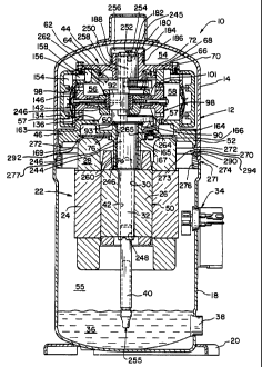
particular by referring to Fig. 1, a scotch yoke type compressor assembly 10
is shown
having a housing generally designated at 12. The rotation of the crankshaft is
converted
to a reciprocation motion by means of a scotch yoke mechanism so as to drive
the four-
cylinder compressor mechanism illustrated in the drawings. One prior
compressor of this
type is illustrated in U.S. Patent No. 5,288,211 (Fry), which is assigned to
the assignee of
the present invention. Another such compressor is disclosed in U.S. Patent No.
4,842,492 (Gannaway) which is also assigned to the assignee of the present
invention.
Housing 12 has a top portion 14 and a bottom portion 18. The two housing
portions are hermetically secured together as by welding or brazing. A
mounting flange
20 is welded to the bottom portion 18 for mounting the compressor in a
vertically upright
position.
Located within hermetically sealed housing 12 is an electric motor generally
designated at 22 having a stator 24 and a rotor 26. The stator is provided
with windings
28. Rotor 26 has a central aperture 30 provided therein into which is secured
a crankshaft
32 by an interference fit. A terminal cluster 34 is provided for connecting
the compressor
to a source of electric power.
Compressor assembly 10 also includes an oil sump 36 located in bottom portion
18. Oil sight glass 38 is provided in the sidewall of bottom portion 18 to
permit viewing
of the oil level in sump 36. A centrifugal oil pick-up tube 40 is press fit
into a
counterbore 42 in the end of crankshaft 32.
Also enclosed within housing 12, in the embodiment shown in Fig.l, is a scotch
yoke compressor mechanism generally designated at 44. A description of a basic
scotch
yoke compressor design is given in U.S. Patent 4,838,769 assigned to the
assignee of the
present invention.
Compressor mechanism 44 comprises a crankcase or cylinder block 46 including
a plurality of mounting lugs to which motor stator 24 is attached such that
there is an
7a
CA 02253033 2002-11-14
annular air gap 50 between stator 24 and rotor 26. The lower portion 52 of
crankcase 46
divides the interior of housing 12 into an upper chamber 54 at high or
discharge pressure
in which the compressor mechanism 44 is mounted, and a lower chamber 55 at low
or
suction pressure in which motor 22 is disposed. Axial passages 57 extend
through
crankcase 46 to provide communication between yoke cavity 262 and lower
chamber 55,
via suction muffler baffle plate 166, discussed in detail below.
7b
CA 02253033 1998-11-06
Compressor mechanism 4=l, as illustrated in one typical embodiment, takes the
form
of a reciprocating piston, scotch yoke compressor. More specifically,
crankcase 46 includes
four radially disposed cylinder bores or compression chambers ~8. Crankcase 46
may be
constructed by conventional casting techniques. The four radially disposed
cylinder bores
open into and communicate with a central suction cavity 60 defined by inside
cylindrical wall
62 in crankcase 46. A relatively large pilot hole 64 is provided in a top
surface 66 of
crankcase 46. Various compressor components, including crankshaft 32, are
assembled
through pilot hole 64. A top cover such as cage bearing 68 is mounted to the
top surface of
crankcase 46 by means of a plurality of bolts 70 extending through bearing 68
into top
surface 66. When bearing 68 is assembled to crankcase 46, and O-ring seal 72
isolates
suction cavity 60 from a discharge pressure space defined by upper chamber 54
of housing
12.
Crankshaft 32 is rotatably journalled in crankcase 46, and extends through
suction
cavity 60. Crankshaft 32 includes a counterweight portion 90 and an eccentric
portion 92
located opposite one another with respect to the central axis of rotation of
crankshaft 32 to
thereby counterbalance one another. The weight of crankshaft 32 and rotor 26
is supported
on thrust surface 93 of crankcase 46.
Eccentric portion 92 is operably coupled by means of a scotch yoke mechanism
94 to
a plurality of reciprocating piston assemblies corresponding to, and operably
disposed within,
the four radially disposed cylinders in crankcase 46. As illustrated in Fig.
1, piston
assemblies 98, representative of four radially disposed piston assemblies
operable in
compressor mechanism 44, are associated with cylinder bores 58.
Compressed refrigerant within each cylinder bore 58 is discharged through
valve plate
136. With reference to cylinder 58 in Fig. 1, a cylinder head 134 is mounted
to crankcase 46
::ODMA\PCDOCS\FWDOCS 1\381\i 8
CA 02253033 2002-11-14
with valve plate 136 interposed therebetween. Valve plate gasket is provided
between
valve plate 136 and crankcase 46. Discharge valve assembly 142 is situated on
the top
surface of valve plate 136. Generally, compressed gas is discharged through
valve plate
136 and past a discharge valve 146.
A discharge chamber 154 is defined by the space between the top surface of
plate
136 and the underside of cylinder head 134. Discharge gas within discharge
chamber
154, associated with each respective cylinder, passes through a respective
connecting
passage 156 in crankcase 46. Connecting passage 156 provides communication
from
discharge space 154 to a top annular muffling chamber 158. Top muffling
chamber 158,
common to and in communication with all of the compression chambers 154, is
defined
by an annular channel formed in the top surface of crankcase 46 and a top
cover portion
of bearing 68. Connecting passage 156 passes not only through crankcase 46,
but also
through holes in valve plate 136 and the valve plate gasket.
Fig. 7 illustrates an alternative arrangement for bearing 68 in which
secondary
discharge muffling chamber 300 is provided for additional muffling to further
quiet
compressor operation. In the particular embodiment shown, passage 302 is
provided in
bearing 68 intermediate primary discharge muffling chamber 158 and secondary
muffling
chamber 300 to communicate discharge fluid therethrough. Secondary muffling
chamber
300 is defined by bearing 68, concentric annular body or wall 304, lower wall
portion of
seal cap 180, and chamber cover 308. Bolts 70 secure cover 308 and annular
wall 304 to
bearing 68. In this alternative arrangement, exit ports 161 (see Fig. 5) may
be formed in
secondary muffling chamber 300. Although the alternative arrangement for
secondary
muffling chamber 300 is shown utilizing a two-piece construction, it should be
understood that the secondary muffling chamber may be formed by using a three-
piece
approach, e.g., a second inner annular wall is provided about separate and
independent
seal cup 180, a one piece approach, wherein wall 304, cover 308, and a second
annular
9
CA 02253033 2002-11-14
wall or seal cup 180 are integral one with the other, or any of a number of
arrangements.
Further, seal cup 180 may be rendered unnecessary by forming suction pressure
area 256
directly in bearing 68, which may be integral with secondary muffling chamber
cover
308.
An internal baffling system, not shown, may be located within first discharge
muffling chamber 158. The baffle arrangement may include baffles, preferably
formed
by web members on crankcase 46, that divide muffling chamber 158 into a
plurality of
sub-chambers. The baffles partially separate the discharge valve assemblies
142 from
each another and include a top wall that is spaced away from the top cover
portion of
bearing 68 to permit refilgerant to flow between the sub-chambers. The top
wall is
spaced away from the top cover portion to create a restricted opening or
clearance
passage in which compressor cross talk or pressure pulses are throttled and
reduced.
Additionally, pressure pulses traveling out of passage 156 impact the baffles
and are
reduced in magnitude.
Top muffling chamber 158 communicates with housing upper chamber 54 (see
Fig. 5) by means of axial exit passageways 159 and radial ports 161 provided
in
crankcase 46. Suction muffler chamber 163 is defined by annular channel 164
and
suction muffler cover plate 166 (Figs. 2 and 3). Cover plate 166 is mounted at
bottom
surface 76 of crankcase 46 at a plurality of circumferentially spaced
locations such as by
bolts in threaded holes.
Typically, compressor 10 is a component of a closed loop system and is
disposed
intermediate an evaporator, suction pressure side, which is connected to lower
housing
chamber 55, and a condenser, discharge pressure side, which is connected to
upper
housing chamber 54. A portion of the cylinder bores and the rear surfaces of
piston
assemblies 98 define suction chambers 56. During operation of compressor 10,
crankshaft 32 rotates causing piston assemblies 98 to reciprocate within the
cylinder bores
CA 02253033 2002-11-14
formed in the crankcase. During the suction phase of the piston stroke, the
reciprocating
action of the piston causes refrigerant at suction pressure to be drawn into
lower housing
chamber 55 via suction inlet tube 135 (see Fig. 4). Suction gas from lower
housing
chamber 155 is drawn into muffling chamber 163 via annular opening defined by
muffling plate 166 and bearing hub 167 formed in crankcase 46. Suction gas
from
muffling chamber 163 is drawn into suction cavity 60 and suction chamber 56
via axial
passages 57 formed in crankcase 46. Suction valve 99 opens to permit
communication of
suction gas from suction chamber 56 into compression chamber 58 via passages
101. The
piston stems pass through the suction cavity and are connected to the
yoke/crankshaft. In
the alternative the suction inlet tube may be connected directly to the
compressor
mechanism such as at yoke cavity 262. Relatively cool suction gas flows from
yoke
cavity 262 (see Fig. 7) into lower housing area 55 and surrounds motor 22 to
provide cool
efficient motor operation. This alternative arrangement would result in
quieter
compressor operation. As any given piston 98 starts its compression stroke,
the
associated suction valve 99 located at the face of the piston, closes and the
piston
compresses the refrigerant in compression chamber 58. During the compression
phase
the piston moves from bottom dead center position to top dead center position,
thereby
compressing gaseous refrigerant within compression chamber 58 and forcing same
through the discharge port in valve plate 136, past discharge valve 142,
through discharge
chamber 154, connecting passage 156, and into conmion discharge chamber 158.
As shown in Fig. 5, the compressed refrigerant then travels through
passageways
159 and radial ports 161 into upper housing chamber 54. In an alternative
arrangement to
that shown in Fig. 5, a wall may extend upwardly from plate 68, either
separate from or
integral with the plate, and a second such plate, again either separate or
integral with plate
68 and the
11
CA 02253033 1998-11-06
wall, disposed over the wall to provide an enclosed area. With openings
provided in plate 68,
the enclosed area may serve as an additional discharge muffler cavity to
further quiet
compressor operation. Further, in such a configuration exit ports 161 may be
provided in the
wall of the second discharge muffler rather than in the crankcase. The
additional discharge
muffler may be of one, two, or three-piece construction.
The discharge pressure refrigerant e:cits upper housing chamber ~4 via
discharge tube
137 and into the condenser portion of the system. Cylinder head gaskets and
discharge shock
loop connecting tubing are not required in this design because the entire
upper housing is at
discharge pressure. At the end of the compression cycle, the discharge valve
closes and the
next suction cycle begins with the suction valve on the piston opening. The
above
compression process is repeated throughout compressor operation.
Fig. 5 shows connecting passage 156 as comprising a plurality of holes 230
through
crankcase 46, associated with each radially disposed cylinder arrangement, to
connect
between discharge chamber 154 and top muffling chamber 158. A suction inlet
opening 232
is included in crankcase 46, providing communication between suction inlet
tube 135 and
suction cavity 60.
The high/low pressure compressor of the present invention provides an
environment
in which the motor and lubrication system are operating at system low or
suction pressure
condition, which provides for a cool efficient motor and lubrication system.
The high
temperature portion of the compressor, the compressor mechanism, is in the
discharge portion
of the system. The valve plate divides the compressor mechanism into a
discharge portion
and a suction portion, with the compression/suction chamber defined by the
cylinder bore
being at high, low, or intermediate pressure depending upon the phase of the
compression
cycle. This provides for a means of allowing the heat of compression to be
dissipated to the
::ODMA\PCDOCS\FWDOCS 1\381 \ 1 12
CA 02253033 1998-11-06
condenser side of the system via the high pressure portion of the housing as
opposed to the
evaporator or low side of the system. In this manner, the motor and
lubrication system are
cooled by the cool suction gas that is returning from the system evaporator.
Discharge gas
from the compressor flows from the compressor to the system condenser and then
to the
evaporator for return to the suction or low side of compressor 10.
In this manner, the hermetic housing is divided into separate high discharge
pressure
and low suction pressure areas and related to the refrigerant system. This
division of pressure
is accomplished by using the compressor crankcase as it is mounted into the
compressor
along with a seal cap placed at the end of the crankshaft opposite the sump.
Cool, low
pressure gas is received and contained in the bottom portion of the
compressor, which houses
the motor and lubrication system. Accordingly, the motor is surrounded by low
temperature
suction gas and oil in the sump is in thermal exchange relation with the
suction gas. The
suction gas maintains a reduced temperature motor operating condition, thereby
enhancing
motor operation, reliability, and efficiency. The suction gas provides a
reduced temperature
1 S lubricating oil for delivery to the various bearing and mechanical
components of the
compressor, thereby enhancing bearing operation, reliability, and life.
Oil returned via suction inlet gas to the lower housing is separated by first
being
drawn over the motor windings. Further oil separation is accomplished by
suction muffler or
baffle plate 166, which directs the suction gas to the center of the
compressor mechanism and
motor/rotor. The upper end of rotor 26 is provided with fan-like blade
protuberances that
face the muffler plate and help separate the oil from the suction gas. As
rotor 26 turns, it acts
as a centrifuge and separates oil and liquid refrigerant from the suction gas
and reduces
refrigerant-oil slugging that can occur during start-up and running operation.
After the
::ODMA\PCDOCS\FWDOCSI\381\I 13
CA 02253033 1998-11-06
suction gas is drawn through opening 165 and into suction muffler cavity 163,
the suction aas
is drawn into the compression cylinders via ports in the cylinders as
discussed above.
In one embodiment, suction refrigerant enters compressor I O via an inlet
provided
through lower housing portion 18 and occupies low pressure area 5~. From low
pressure area
55, suction refrigerant is drawn into the compressor unit. During compressor
operation,
pistons 98, or comparable components in different compressor types, permit
suction
refrigerant contained in suction area 56 of yoke cavity 262, by operation of
suction intake
valves or the like, to flow from suction area 56 into compression chamber 58.
The pistons
then act on the refrigerant contained in the compression chamber by
compressing the
refrigerant to a discharge pressure. The refrigerant is then discharged
through valuing
mechanisms 142 or the like into discharge chamber 154. The action of the
pistons results in a
pressure drop within yoke cavity 262 which is seen at crankcase passages 57.
This pressure
drop draws refrigerant from the low pressure area surrounding the motor into
suction muffler
chamber 163 via annular opening 165 and then into suction area 60 of yoke
cavity 262. In
essence, during compressor operation there are three separate areas at
different levels of low
pressure within the overall low pressure section of the compressor. Yoke
cavity 262 is at a
first low pressure level that is generally somewhat lower than a second Iow
pressure level in
suction muffler chamber 163 that is generally somewhat Iower than a third low
pressure level
in low pressure area 55 surrounding motor 22. Fan-blade like protuberances
located at the
top of rotor 26 create a centrifugal effect that acts upon the liquid
refrigerant forcing it
outward through gap 169 formed between the upper surface of windings 28 of
stator 24 and
muffler plate 166 into lower housing chamber 55. This enhances compressor
operation and
efficiency by reducing liquid slugging from occurring. One alternative
arrangement is to
::ODMA\PCDOCS\FWDOCS 1\381\ 1 14
CA 02253033 2002-11-14
connect the source of suction refrigerant directly with the compressor unit,
such as
providing an inlet through upper housing portion 14 and directly into yoke
cavity 262.
With respect to the lubrication system employed in compressor 10, examples of
particular lubrication systems used in refrigeration compressors are described
in more
detail in U.S. Patent No. 5,232,351 (Robertson, et al.), relating to a
lubrication system
used in a reciprocating type compressor, U.S. Patent No. 5,131,828 (Richardson
Jr, et
al.), relating to a lubrication system in a scroll compressor, and U.S. Patent
No.
5,785,1 S 1 (Fry, et al). The referenced patents are assigned to the assignee
of the
present invention.
As the oil lubrication system of compressor 10 is disposed in the low suction
pressure area of the compressor, oil delivered to compressor mechanism
components is
preferably maintained at low pressure. If the oil lubrication path were
permitted to be in
communication with the high discharge pressure area, the pressure differential
would
greatly reduce the ability of the lubrication system to deliver oil to the
parts in need of
lubrication. Accordingly, seal cap 180 is provided at upper end 182 of
crankshaft 32. As
shown in Fig. 1, seal cap 180 s held in place atop hub 184 of bearing cover 68
by
crimping the lower end of the seal cap into crimping groove 186 formed in hub
184. In
the alternative, as shown in Fig. 5, seal cap 180' may be provided with
annular shoulder
181 and may be held in place by a retention spring 183 or spacer or the like.
As a third
alternative, the seal cap may be formed in or be a part of upper bearing plate
68. As
shown in Fig. 7, a second groove is formed in the hub for receiving O-ring
seal 188 for
sealing the low pressure area defined by the inner surface of the seal cap and
the hub from
high pressure area 54.
T'he lubrication system illustrated in Fig. 1 operates as follows, oil pick-up
tube
40 is partially disposed within oil sump 36 to draw oil from sump 36 into
axial oil
passageway 42
CA 02253033 1998-11-06
of crankshaft 32, and up through offset oil passageway 244. A plurality of
radial
passageways 246, are provided to communicate lubricating oil from sump 36 to
the various
moving parts of compressor 10, including piston assemblies 98.
Crankshaft 32 includes counter bore 248 to provide a recess into which oil
pick-up
tube 40 is disposed. As crankshaft 32 rotates, oil is drawn in through inlet
56 and migrates
upward by centrifugal force along the interior wall of the tube and into axial
oil passageway
42 of shaft 32 and results in a pressure drop at inlet 255.
Alongside oil passage 244 in upper end portion 245 of the crankshaft is
provided vent
passage 250, which may be offset with respect to the axis of the crankshaft.
Vent passage
250 is partially threaded, or otherwise adapted, to receive hollow bolt 254
having inner
passage 252 formed therein. In one alternative, a hollow plug may be simply
pressed into the
bore that forms vent 250. Seal cup 180 and the upper end of crankshaft 32 form
an area, 256,
at suction pressure. Passages 250 and 252 provide fluid communication between
area 256
and low pressure yoke cavity 262. The reciprocating action of the compressor
mechanism,
which draws suction fluid into the yoke cavity, causes a pressure drop to
occur along
passages 250 and 252 and within area 256. This pressure drop, in addition to
the centrifugal
force associated with the oil pick-up tube, urges oil to flow upward through
passageway 244
and into area 256. The rotating action of the crankshaft slings the oil
entering area 256
radially outward against the wall of cup 180, or in the alternative a bearing
housing portion of
hub 184. This also serves as a trap to collect foreign debris material, and
thus prevent such
debris from damaging the bearing. The oil then travels downward between the
inner bore of
hub 184 and the outer cylindrical surface of crankshaft 32 and joins oil from
radial passages
246 to feed lubricating oiI across rotational bearing 258 and to various
compressor
components. The oil delivered across bearing 258 then flows into yoke cavity
262 to
::ODMA~PCDOCS~FWDOCS 138111 16
CA 02253033 1998-11-06
lubricate various compressor mechanism components and eventually, by operation
of gravity,
collects in the bottom portion of yoke cavity 262, such as in the cavity
formed by channel
264, which may or may not be provided in the crankcase. The head of bolt 254
acts as a dam
to prevent the flow of oil from area 256 from bypassing bearing 258 by flowing
directly into
passages 250 and 252 and into yoke cavity 262. Should area 256 become filled
with oil. then
some oil will flow directly into yoke cavity 262 via passages 250 and 252.
Bearing 260 is
lubricated by oil delivered via radial passages 246.
Oil that is collected in channel 264 generally drains by operation of gravity
through
passages 57 formed in crankcase 46. Rotating counterweight 90 provides a
pumping action
to aid in removing oil collected in channel 264 from the crankcase. Holes or
passages 57 may
be drilled or formed in crankcase 46 and provide a return flow path for oil
from the yoke
cavity to the oil sump. Passages 57 should be sized so that suction gas
entering yoke cavity
262 from suction muffler chamber 163 does not effect the flow of oil back to
the oiI sump and
the oil flow does not effect the flow of suction gas. As an alternative to or
in addition to
passages 57, bolts 265 may be provided with a bore for draining oil from the
crankcase
through baffle plate 166 to oil sump 36.
As shown in Figs. l and 5, the present invention further involves providing an
annular
acoustic insulation device 270 intermediate crankcase 46, which is typically
made from cast
iron, and annular welding ring 276, which is preferably made from steel and
welded or
otherwise secured to lower and upper housing members 14 and 18 at intersection
271 to
hermetically seal same together. A protuberance or tab 277 extends from the
outermost side
surface of the welding ring and into the gap between housing members 14 and 18
at
intersection 271 to facilitate the welding or bonding process. With acoustic
insulator 270
received in and secured to recess 272 of crankcase 46 and recess 274 of weld
flange 276, gap
::ODMA~PCDOCS~F'WDOCS I~381 \ I 17
CA 02253033 1998-11-06
273 is formed between the crankcase and the weld flange and clearance 290 is
formed
between the insulator and the housing. It is preferred that a clearance be
formed between the
housing and the crankcase. The acoustic insulator is preferably made from
vibration
absorbing materials, such as neoprene-based elastomers, butylene-type
elastomers, silicon-
based elastomers, dense fiber type elastomers, etc. During normal operation a
pressure
differential occurs between the upper housing area and the lower housing area
causing
elastomeric insulator 270 to become compressed and gap 273 and clearance 290
to narrow.
During abnormal compressor operation an excessively high pressure differential
condition
may occur that is su~cient to cause crankcase 46 to engage weld flange 276 at
respective
surfaces 292 and 294, thereby effectively eliminating gap 273. Clearance 290
may become
narrowed, but, even during abnormal conditions, is preferably not eliminated,
thereby
preventing the elastomeric insulator from rubbing against the housing which
may cause
unnecessary and premature deterioration of the insulator. The insulator
prevents the
crankcase from engaging the welding ring during normal operation and deflects
so as to
absorb loads associated with compressor operation. The insulator isolates
vibrations from
the crankcase and reduces the communication of same to the housing. The
elastomer-based
insulator has memory and essentially returns to its normal, pre-load shape
once a load
dissipates.
The acoustic insulator may be mechanically or otherwise bonded or secured to
the
crankcase and the annular welding flange, and forms a part of the high to low
pressure seal.
Figs. 1 and 5 illustrate a chemical bonding between the insulator and the
crankcase and the
weld flange at their respective recesses. By way of example and not
limitation, acceptable
bonding methods include: ultrasonic welding, solvent welding, acrylic
adhesive, and hot
metal bonding. An example of a mechanical bond between insulator 270 and the
crankcase
::ODMA\PCDOCS\FWDOCS 1\38l\ I 1 S
CA 02253033 1998-11-06
and the weld flange is illustrated in Fig. 6 in which bolts 278 having heads
280 are formed
directly in and are encased by elastomeric insulator 270 with threaded lugs
282 extending
therefrom. Lugs 282 are received in bores 284 and 286 formed in weld flange
276 and
crankcase 46, respectively, and extend therefrom so as to threadingly receive
nuts 288. In
this manner, insulator 270 is mechanically bonded or attached to the crankcase
and the weld
flange. Other devices, such as rivets, screws or other fasteners, may be
employed to secure
insulator 270 to the crankcase and the weld flange.
While this invention has been described as having a preferred design, the
present
invention can be fiurther modified within the spirit and scope of this
disclosure. This
application is therefore intended to cover any variations, uses, or
adaptations of the invention
using its general principles. Further, this application is intended to cover
such departures
from the present disclosure as come within known or customary practice in the
art to which
this invention pertains and which fall within the limits of the appended
claims.
::ODMA\PCDOCS\FWDOCS 1\381\ t 19