Language selection

Search

Patent 2253210 Summary

Third-party information liability

Some of the information on this Web page has been provided by external sources. The Government of Canada is not responsible for the accuracy, reliability or currency of the information supplied by external sources. Users wishing to rely upon this information should consult directly with the source of the information. Content provided by external sources is not subject to official languages, privacy and accessibility requirements.

Claims and Abstract availability

Any discrepancies in the text and image of the Claims and Abstract are due to differing posting times. Text of the Claims and Abstract are posted:

  • At the time the application is open to public inspection;
  • At the time of issue of the patent (grant).
(12) Patent Application: (11) CA 2253210
(54) English Title: CONTAINING STRUCTURE FOR LIFT MACHINERY
(54) French Title: STRUCTURE CREUSE POUR MACHINERIE D'ASCENSEUR
Status: Deemed Abandoned and Beyond the Period of Reinstatement - Pending Response to Notice of Disregarded Communication
Bibliographic Data
(51) International Patent Classification (IPC):
  • B66B 11/00 (2006.01)
(72) Inventors :
  • MARTINI, ANGELO (Italy)
  • BONNARD, LUC A. (Switzerland)
(73) Owners :
  • INVENTIO AG
  • GMV S.P.A.
(71) Applicants :
  • INVENTIO AG (Switzerland)
  • GMV S.P.A. (Italy)
(74) Agent: RICHES, MCKENZIE & HERBERT LLP
(74) Associate agent:
(45) Issued:
(86) PCT Filing Date: 1997-05-05
(87) Open to Public Inspection: 1997-11-13
Availability of licence: N/A
Dedicated to the Public: N/A
(25) Language of filing: English

Patent Cooperation Treaty (PCT): Yes
(86) PCT Filing Number: PCT/IB1997/000485
(87) International Publication Number: IB1997000485
(85) National Entry: 1998-10-26

(30) Application Priority Data:
Application No. Country/Territory Date
MI96A000937 (Italy) 1996-05-09

Abstracts

English Abstract


Containing structure (10) for a lift machinery, the structure being made of
metal or other suitable material, consisting of a housing (18) in which at
least one of the constituent walls is defined by leaves hinged to a permanent
wall (14) of the building or to another wall of the housing (18). The object
of the present invention is to provide a containing room or structure for lift
machinery, occupying very little space and at the same time providing enough
space for maintenance work. A permanent fixed room within the building for the
lift machinery is not required.


French Abstract

Cette invention concerne une structure creuse (10) pour machinerie d'ascenseur, laquelle structure est faite de métal ou de tout autre matériau adéquat. Cette structure comprend un logement (18) dans lequel l'une au moins des parois constituantes est définie par des plaques, ces dernières étant fixées par une charnière à un mur permanent (14) du bâtiment ou à une autre paroi dudit logement (18). Cette invention a pour but d'obtenir une chambre ou une structure creuse destinée à la machinerie de l'ascenseur, et qui occupe très peu de place tout en offrant un espace suffisant pour les travaux d'entretien. Une chambre fixe et permanente située dans le bâtiment et destinée à la machinerie de l'ascenseur n'est pas nécessaire.

Claims

Note: Claims are shown in the official language in which they were submitted.

~
CLAIMS
1. Containing structure (10) for a lift machinery, the structure
being made of metal or other suitable material and consists of a
housing (18) in which at least one of the constituent walls is defined
by leaves hinged to a wall of the housing (18),
characterised by,
that the opening of leaves (20), (20'), (22) and the joining together
along a vertical axis defines a space (24) oriented to the front with
respect to the lift machinery and when the leaves (20), (20'), (22)
are closed up, the housing (18) has a dimension substantially
equivalent to the space occupied by the lift machinery.
2. Containing structure (10) according to claim 1, characterised in
that said housing (18) is located in correspondence with a landing
doorway (12) of a lift shaft bounded by permanent walls (14) and open
on at least one side in correspondence with the access (16) to the
landing.
3. Containing structure (10) according to claim 2, characterised in
that said housing (18) is located beside the doorway (12) and in front
of the space provided for the opening of the automatic shaft doors
(28), replacing a piece of shaft wall.
4. Containing structure (10) according to claim 1, characterised in
that said housing (18) contains the necessary equipment for a
hydraulic lift machinery including a pumpunit (32) and control
equipment.
5. Containing structure (10) according to claim 1, characterised in
that said wall consists of leaves (20), (20'), (22) and forms the
front face (18') of the housing (18).
6. Containing structure (10) according to the preceding claims,
characterised in that it has at least one lock or bolt for locking the
leaves (20), (20'), (22) to each other and to the housing (18).

~
7. Containing structure (10) according to one or more of the
preceding claims, characterised in that one or more of the leaves
(20), (20'), (22) consists of a plurality of elements or panels.
8. Containing structure (10) according to one or more of the
preceding claims, characterised in that, the leaves (20), (20'), (22)
are provided with an isolation layer to prevent sound emission.

Description

Note: Descriptions are shown in the official language in which they were submitted.


CA 022~32l0 l998-l0-26
Containing Structure for Lift Machinery
DESCRIP ION
The present invention relates to a containing structure for l ft
machinery.
More particularly, the present invention relates to a con_a1ning
structure or room for lif- machinery, consisting of an expansible
s~ructure located, for e~ample, in the doorway present in
cor~esponder.ce with each stop along the lift shaft.
As is known, the construction of lift equipment for passengers and
l~ goods is regula_ed by specific standards which require that, amongst
other thir.gs, a suitable room be provided for containing the
electrica' ccntrol cabinet and machinery, or power unit _hat powers
the cage mcvement.
~0 So 'he d mensior.s of this room in relation to the space occupied by
the equ pmen installed therein must be sufficient, and there must be
a minimum amount of free spac~e allowing access for the operative who
carries out maintenance.
2~ This room must not, of course, be accessible to unauthorised persons
and is therefore fitted with a lockable door.
The creation of a room of this kind inevitably reduces the space
available within the building for residential or shared use.
EP 680 921 discloses a containing structure contains an instrument
panel of an elevator, which is placed in the same opening in the wall
of the elevator shaft as the landing door of the elevator. The
containing structure consists of a cover which is removable or it may
3~ be so hinged that it can be turned aside off the instrument panel.
AME~I~ED S~lEET

CA 022~3210 1998-10-26
The above mentioned containing structure does not provide a suitable
room with a minimum amount of free space allowing access for the
operative who carries out maintenance work.
The ocjec~ cf the present invention is the avoidance o- the
inconveniences recited in the foregoing.
More particularly, the object of the present invention is to provide a
containing room or structure for lift machinery, occupying very little
space and at the same time providing enough space for maintenance
work.
Another object of the invention is to provide a containing structure
as def ned above that does not require the design and cons~ruction of
1~ a permanent fixed room within the building.
Another object of the invention is to provide a conta~nir.g s_ructure
with small dimensions to fit into the space which is for example lef-
beside the lift shaft docr.
~O
A further object of the invention is to provide a containing structure
which accommodates all necessary machinery equipment in a single room
to achieve an easy and time-saving maintenance.
2~ These and still other objects of the invention are achieved with the
containing structure for lift machinery of the present invention
which, made of metal or other suitable material and consists of a
housing in which at least one of the constituent walls is defined by
leaves hinged to a wall of the housing, characterised by, that the
opening of leaves and the joining together along a vertical axis
defines a space oriented to the front with respect to the lift
machinery and when the leaves are closed up, the housing has a
dimension substantially equivalent to the space occupied by the lift
machinery.
ENDc~ S~EET

CA 022~3210 1998-10-26
The lift machinery preferably consisting of 2 hydraulic drlve system
has a pumpunit, arranged with its axle in a vertical position to
achieve a slim shape of the containing structure.
The constructional and functional characteristics of the c-n~a ning
structure for lift machinery of the present invention will be made
clearer in the following description, in which reference is ~ade to
the attached sheet of drawings depicting a preferred and non-
iimitat ve embodiment, in which:
I()
AME~ 9 ~EE-F

CA 022~3210 1998-10-26
WO97/42119 PCT~B97100485
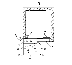
Fig.1 schematically shows a lift shaft with the containing structure
of the present invention.
With reference to figure 1, the containing structure for lift
machinery, indicated in entirety by 10, is located, according to a
preferred, but not critically important, embodiment, in
correspondence with a landing doorway 12 of a lift shaft bounded by
permanent walls 14 and open on at least one side in correspondence
with the access 16 to the landing.
According to the invention, the containing structure 10 basically
consists of a housing 18 advantageously made of metal, which houses
an electrical cabinet and power unit of the type known per se; the
housing 18, which may, for example, be parallelepipedonal, is
composed of metal panelling of suitable dimensions with regard to
thickness to form side walls, back wall, base and top or ceiling. The
front wall, which constitutes the access door, is formed by a
plurality of leaves hinged to each other so that they can be folded
together and/or against the front face of the housing 18. Fig. 1
illustrates by way of example the containing structure 10, the front
wall 18' of which consists of three leaves 20, 20' and 22 fully
opened and oriented preferably at right angles to each other; the
opening of these leaves causes the creation of a space 24 whose
dimensions are such as to comply with the re~uirements of current
regulations, especially as regards the amount of free frontal space.
The same Figure 1 indicates the movement of said leaves by the arrows
A, B and C; the said leaves 20, 22, in the proposed illustrative
embodiment, are connected together and hinged, for example, along the
vertical wall 26, while the leaf 20' is an independent element.
Obviously, the leaves 20, 22 and/or 20' can be formed from a number
of parts or panels hinged to each other and able to be oriented in
any direction to form the perimeter walls of the space 24. The bases
of the various leaves, which are raised slightly of the floor

CA 022~32l0 l998-l0-26
WO97/42119 PCTnB97/00485
surface, can be provided with wheels, balls or equivalent means for
facilitating the opening and sliding of the leaves themselves, which
when open form the space 24. The latter is provided with a lock or
bolt ~not illustrated), which is preferably disposed on the leaf 20
and can engage with the corresponding catch disposed on the edge of
one side of the housing 18. For maximum space saving the housing 18
is located beside the doorway 12 and in front of the space provided
for the opening of automatic shaft doors 28, replacing a piece of
shaft wall.
During operation of the lift, the leaves 20, 20', 22 which form the
front wall 18' of the housing 18 are folded together and in the
direction of the housing itself, the resulting total dimensions of
which are, as a consequence, extremely small. When the attendance of
staff is required for maintenance or repair involving access to the
electrical cabinet and/or to the power unit, the leaves 20, 20', 22
are opened and oriented towards the outside, for example, with a
mutually perpendicular arrangement, and define the space 24
dimensioned according to the current standards; the operative
positions himself inside this space and can close the leaf 22, which
acts as a door, using the same lock which serves to close the
complete assembly, or an independent lock or bolt located on the
inside front of one and/or the other of said leaves.
25 For a lift with a payload of 630 kg the containing structure 10 has a
width of only 500 mm, so that the space beside the door is sufficient
to place it. The housing 18 contains all the necessary equipment for
a hydraulic lift machinery including a oiltank 30, a pumpunit 32
inside the oiltank connected to a pressure tube 34 leading to a jack
arrangement inside the shaft, power supply, valves and control
equipment. The oiltank is about 300 mm x 500 mm x 1200 mm. The hole
machinery is not higher than a building floor, in the described
embodiment about 1900 mm. Nevertheless full access to all machine
parts is pro~ided for the operative.

CA 022~3210 1998-10-26
The invention as described above and claimed below is proposed,
however, purely illustratively, it being understood that the same can
be susceptible of many modifications and variants which yet remain
within the scope of Ihe inventive concept. For example the leaves can
be only solitary and the space for the operative can be secured bv
barrie~s.
It will be understood, in particular, that structural reversals or
1~ alte~native positionings of the components or parts that together ma.~e
up the containing structure for the lift machinery of the present
invention are possible within the scope of the appended cla ms.
0~ T

Representative Drawing
A single figure which represents the drawing illustrating the invention.
Administrative Status

2024-08-01:As part of the Next Generation Patents (NGP) transition, the Canadian Patents Database (CPD) now contains a more detailed Event History, which replicates the Event Log of our new back-office solution.

Please note that "Inactive:" events refers to events no longer in use in our new back-office solution.

For a clearer understanding of the status of the application/patent presented on this page, the site Disclaimer , as well as the definitions for Patent , Event History , Maintenance Fee  and Payment History  should be consulted.

Event History

Description Date
Application Not Reinstated by Deadline 2002-05-06
Time Limit for Reversal Expired 2002-05-06
Deemed Abandoned - Failure to Respond to Maintenance Fee Notice 2001-05-07
Inactive: IPC assigned 1999-04-06
Inactive: IPC removed 1999-04-06
Inactive: First IPC assigned 1999-04-06
Inactive: Single transfer 1999-03-02
Inactive: IPC assigned 1999-01-14
Classification Modified 1999-01-14
Inactive: First IPC assigned 1999-01-14
Inactive: Courtesy letter - Evidence 1998-12-29
Inactive: Notice - National entry - No RFE 1998-12-23
Application Received - PCT 1998-12-18
Application Published (Open to Public Inspection) 1997-11-13

Abandonment History

Abandonment Date Reason Reinstatement Date
2001-05-07

Maintenance Fee

The last payment was received on 2000-04-18

Note : If the full payment has not been received on or before the date indicated, a further fee may be required which may be one of the following

  • the reinstatement fee;
  • the late payment fee; or
  • additional fee to reverse deemed expiry.

Patent fees are adjusted on the 1st of January every year. The amounts above are the current amounts if received by December 31 of the current year.
Please refer to the CIPO Patent Fees web page to see all current fee amounts.

Fee History

Fee Type Anniversary Year Due Date Paid Date
MF (application, 2nd anniv.) - standard 02 1999-05-05 1998-10-26
Registration of a document 1998-10-26
Basic national fee - standard 1998-10-26
MF (application, 3rd anniv.) - standard 03 2000-05-05 2000-04-18
Owners on Record

Note: Records showing the ownership history in alphabetical order.

Current Owners on Record
INVENTIO AG
GMV S.P.A.
Past Owners on Record
ANGELO MARTINI
LUC A. BONNARD
Past Owners that do not appear in the "Owners on Record" listing will appear in other documentation within the application.
Documents

To view selected files, please enter reCAPTCHA code :


To view images, click a link in the Document Description column. To download the documents, select one or more checkboxes in the first column and then click the "Download Selected in PDF format (Zip Archive)" or the "Download Selected as Single PDF" button.

List of published and non-published patent-specific documents on the CPD .

If you have any difficulty accessing content, you can call the Client Service Centre at 1-866-997-1936 or send them an e-mail at CIPO Client Service Centre.


Document
Description 
Date
(yyyy-mm-dd) 
Number of pages   Size of Image (KB) 
Abstract 1998-10-25 1 46
Description 1998-10-25 6 204
Claims 1998-10-25 2 51
Drawings 1998-10-25 1 13
Representative drawing 1999-01-21 1 5
Notice of National Entry 1998-12-22 1 192
Courtesy - Certificate of registration (related document(s)) 1999-03-31 1 117
Courtesy - Abandonment Letter (Maintenance Fee) 2001-06-03 1 182
Reminder - Request for Examination 2002-01-07 1 117
PCT 1998-10-25 13 407
Correspondence 1998-12-28 1 30