Note: Descriptions are shown in the official language in which they were submitted.
CA 022~3226 1998-10-27
W O 97/40999 rcTrusg7/o75s6
METHOD AND APPARATUS FOR PROPELLING
A MARINE VESSEL
BACKGROU~nD OF TH~VF.~TION
Field of the InvPntion
The present invention relates generally to a system for propelling marine
vessels. In particular, the invention relates to an auxiliary propulsion system for sail-
s powered marine vessels that uses a combined electric motor and tr:ln~mi.~sion device
having a continuously variable speed output, a stored energy supply for powering the
device, and an electrical recharging system for recharging the stored energy supply.
Description of the Prior Art
Traditionally, llulllelous types of marine vessels have relied on the use of sails
lo as their primary source of motive energy. However, for safety reasons, the larger
classes of sail-powered vessels are typically equipped with auxiliary power sources for
use during low wind conditions or for maneuvering in and out of harbors and slips.
Such auxiliary power sources typically consist of internal combustion engines orelectrically powered motors. Both of these power sources have inherent disadvantages
as will be discussed below.
Internal combustion engines require constant maintenance and often become
environmental hazards after extended use or inadequate maintenance. For example,internal combustion engines require the use of oil-based fuels and lubricants that can
leak and emit unpleasant, unsightly and unsafe odors. In addition, internal combustion
engines are coln~la~ively loud, and often can become unreliable due to age or constant
exposure to the saltwater and extreme weather conditions common to the environment
of marine vessels. The n~cess~ry fuel system and engine block are bulky and add
unwanted weight to marine vessels. Finally, any supply of fuels and lubricants on a
marine vessel can occupy a considerable amount of a vessel's limited space, and also
pose a fire hazard to the vessel and its occupants.
CA 022~3226 1998-10-27
Wo 97/40999 PcTruss7/o7556
On the other hand, electric motors used in marine vessels are generally quieter,less polluting and require less m~ nre than int~ l combustion engines.
However, electric motors also suffer from a ~lul~lbe~ of inherent problems. Electric
motors are usually powered by b.~ ;es which cannot operate for extended periods of
time willlouL recharging. During normal operation, marine vessels are often far from
shore and do not have a ,echalging source. Large banks of bal~elics may be employed
to prolong the amount of time between battery recha,gings. However, like the fuel
tanks, the engine block and the required supplies for an internal combustion engine,
the large banks of batteries needed to run conventional electric motors can be buL~y
0 and heavy.
A need exists, therefore, for an auxiliary propulsion system for marine vessels
that is comparatively lightweight and dependable, occupies less space than the
conventional auxiliary propulsion system, can operate for extended periods of time, and
is not absolutely dependent on land-based facilities for repleni~hm~nt of its energy
supply.
Marine vessels are operated in environments having almost nnlimited energy
sources. For example, as noted above, sail-powered marine vessels use the wind as
their primary motive power source. However, in addition to the wind, such vessels
are typically exposed to several hours of direct s-lnlight, and are surrounded by water
that is co~ ly in motion. The movement of vessels under sail by itself can generate
the movement of water. The wind, sun and water offer sources of energy which could
potentially help power marine vessels.
~onsequently, a further need exists for a propulsiop system for marine vessels
that can harness the energies of the wind, sun or water to a greater degree than is
possible in current conventional marine vessels.
SUMMA~Y OF THE ~ NTION
In view of the disadvantages and sho,lcull~,llg~ present in the prior art, a general
object of the present invention is to provide an apparatus and method for an auxiliary
propulsion system for a sail-powered marine vessel.
.. . .
CA 022~3226 1998-10-27
W O 97140999 PCT~US97/07556
A further general object is to provide an apparatus and method for an
electrically-based auxiliary propulsion system for a sail-powered marine vessel.
Another general object is to provide an ay~alaLus and method for recharging
an electrically-based auxiliary propulsion system for a sail-powered marine vessel.
s It is yet another object of the invention to provide an al~pa~aLus and method for
an electrically-based auxiliary propulsion system for a sail-powered marine vessel that
is comparatively lightweight, efficient and inexpensive.
An even further object of the invention is to provide an apparatus and method
for an electrically-based auxiliary propulsion system for a sail-powered marine vessel
lo that requires less room, or is at least more space efficient, than conventional auxiliary
propulsion systems.
An even further object is to provide an apparatus and method for a propulsion
system for marine vessels that can harness the energies of the wind, sun or water to a
greater degree than current conventional marine vessels.
1S According to one aspect of the invention, the apparatus of the auxiliary
propulsion system generally incorporates means for generating locomotive force to
propel the boat or vessel wherein the locomotive means includes an electric
motor/tr~ncmicsion device, means for storing energy for the electric
motor/tr~ncmiccion device, and means for generating energy from one of at least
s~mlight, wind motion and water motion to be stored in the energy storing means.
According to a more specific aspect of the invention, the auxiliary propulsion
system for a boat or other marine vessel incorporates an electric motor/tr~ncmic.cion
device for generating locomotive force to propel the boat or vessel; an electrical power
supply for providing electrical energy to drive the electric motor/tr~ncmi~sion device;
2s at least one electrica} energy gell~laling device for ge~ alillg electrical energy through
conversion from one of at least sunlight, wind motion and water motion; a charging
circuit having means for controlling charging of the power supply with electrical
. _ . . . ... .
CA 022~3226 1998-10-27
W O 97/40999 PCT~US97/07556
energy from the energy generating device; and means for controlling speed and
direction operation of the electric motor/l~ sion device.
In a further aspect of the invention, a method for providing auxiliary propulsion
for a boat or other marine vessel co~ ises the steps of providing an electric
s motor/Ll~ ---icsion device; hlpullillg electrical energy into the electric
motor/ll,..-~ sion device from an electric power supply; gene~ lg locomotive force
for the boat or other marine vessel using the electric motor/tr~ncmi~sion device when
a ~lil.laly propulsion system of the boat or other marine vessel is inactive; and
generating electrical energy to be stored in the electrical power supply. The step of
lo geneldlmg electrical energy includes the step of converting at least one of sunlight,
wind motion and water motion into electrical energy.
Other objects and fealures of the present invention will be appalcl.L from the
following detailed description of the preferred emboclim~nt~.
BRIEF DESCRIPTION OFTHE DRA~NGS
ls The invention will be further described in conjullction with the accompanying
drawings, in which:
Figure 1 illustrates a system block diagram of an electrically-based,
rechargeable auxiliary propulsion system according to a general embodiment of the
present invention;
Figure 2 illustrates a block diagram of an electrically-based, rechargeable
auxiliary propulsion system according to a preferred embodiment of the present
nvention;
Figure 3 illLI~Ll~lcs one example of a general arrangement for the structure andoperation of the user control panel according to the present invention;
2s Figures 4A - 4C illustrate examples of individual electrical energy generating
sources and their accompanying structural connections to the charging circuit
applicable to the p-cfcl-cd embodiment of the present invention;
Figure 5 shows one example of a general system block diagram for
implementing the use of several electrical energy gellel dLing sources together connected
to the charging circuit of the p-cr~llcd embodiment of the present invention;
CA 022~3226 1998-10-27
W O 97/40999 PCTrUS97/07556
Figure 6 shows a second example of a general system block diagram for
impl~ the use of several electrical energy gell~,a~mg sources together conn~ctçdto an energy input and load management circuit applicable to the ~-~r~,led embodiment
of the present invention;
s Figure 7 shows a system block diagram of the circuit components of one
embodiment for the charging circuit; and
Figure 8 illustrates a general system block diagram of the components
implemPntin~ the energy input and load management circuit applicable to the circuit
of Figure 6.
D~.T~I1F.n DF.~CRIPTION OFTHE PR~FERRED EMBODI~DENTS
With ~ erellce to the figures, like reference cha.acLel~ will be used to in-licate
like elements throughout the several embodiments and views thereof. In particular,
with re~ ce to Figure 1, the propulsion system 10 of the present invention is
generally embodied in a variable speed electric motor/tr~ncmi.csion 12 connectedthrough a shaft to a propeller 14. The motor/l~d~ lission 12 iS a dual-input, infinite-
speed electrically powered motor/L~ lic~ion device as disclosed in U.S. Patent No.
5,067,932, which is incorporated herein by reference.
As explained in U.S. Patent No. 5,067,932, an electric motor/tr~ncmicsion, as
applicable to the present invention, includes a sun gear motor powering a sun gear
assembly, a ring gear motor powering a ring gear assembly and a tr~ncmicsion
assembly. The ring gear assembly can be rotated in a forward or reverse direction at
an infinite number of speeds. To alter the amount of torque delivered by the
motor/tr~ncmi.csion, the sun gear assembly may be rotated in a forward direction, a
reverse direction or may be locked in a stationary position.
In operation, the electric motor/tran~mic.sion 12 drives the propeller 14, thereby
propelling the vessel (not shown) in which the system is installed. The direct
connection from the electric motor/ll~l~lllission 12 to the propeller allows substantially
all of the torque developed by motor/tr~ncmi.csion 12 to be tr:~ncmit~e~l directly to
propeller 14.
CA 022~3226 l998-l0-27
WO 97/40999 PCTrUS97/07556
The electric motor/lL~ si-~n 12 is further conn~cte~1 to a speed control
circuit 16 that varies the electrical power to the electric motor/l-~"~"~;~sion 12, thereby
varying the speed of the electric motor/tr~n~mi~ion 12 and the propeller 14.
Consequently, varying the speed of the propeller varies the speed of the vessel. The
speed control circuit 16 is connected to a user control panel 18. From the user control
panel 18, the speed of the vessel or the amount of power to apply to the propulsion
system 10, along with the direction of rotation of the propeller 14 to effect either
forward or reverse motion can be selected.
The speed control circuit 16 controls the amount of electric power inputted to
lo the electric motor/tl~ sion 12 from the power supply circuit 20. Since a ~le~lled
embodiment of the present invention is primarily directed to be an auxiliary propulsion
system for a sail-powered marine vessel, one conventional impl~nt~tion of the power
supply circuit 20is a bank of batteries, such as car batteries. However, other types of
high capacity electric storage cells may be used for the power supply circuit 20. For
example, co~ lercial versions of the battery cells used in modern diesel submarines
may be applicable.
The speed control circuit 16 can be implemented using a conventional
microprocessor-based control circuit (not shown) as known in the art, wherein user
inputs (i.e., pushing of a button, shifting of a lever, rotating of a dial) into the user
control panel 18 are translated into control signals. The control signals are then
inputted into the speed control circuit 16. The control signals are then intel~ ed by
the microprocessor-based circuit of the speed control circuit 16 to control the amount
of electric power to be fed to the electric motor/tr~n~mi.~sion 12.
The power supply 20is replenished with electrical energy through a charging
2~ circuit 22. The charging circuit 22 controls and regulates the voltage and current
levels inputted into the system for recharging the power supply 20. In an embodiment
of the invention where the power supply 20 consists of a bank of batteries, the charging
circuit 22 as shown in Figure 7 can mclude monilolillg cil~uilly 22a for monitoli-lg
and sign~lling which batteries in a bank of batteries 20a need replenishment or
replacement. Also, the charging circuit 22 can include switching circuitry 22b for
CA 022~3226 1998-10-27
W O 97/40999 PCTrUS97/07556
selectively chalgmg the b~lelies, in order to either evenly regulate the charging of the
batteries or to charge only the batteries that require charging. A charging control
circuit 22c is conn~cted to receive and process signal data from the monitoring
Cil~;uiLly 22a and to control the switching and charging operation of the switching
Cii~;ui~ 22b.
The charging circuit 22 is further conn~cted to at least one electrical energy
input source 24 and an external energy source 26. The electrical input source 24 is
embodied in an electrical energy geneldling device or system that can genelat~
electrical energy with which to charge the power supply 20 while the boat/vessel is
lo moving under sail or even while it is stationary away from the docks. In the prer~ d
embodiment of the invention, such electrical energy generating devices include, as
shown in Figures 4A through 4C, solar panels composed of an array of photoelectric
cells (Figure 4A), wind-powered generators (Figure 4B), and water- or wave-powered
generators (Figure 4C). As shown in Figure 4B, one example of a wind-powered
generator is a windmill-type device consisting of an electrical generator 24b with a
propeller 25 that rotates with the wind.
In the plcr~ d embodiment of the present invention, the water- or wave-
powered generator incorporates the electric motor/tr~ncmic.cion 12 that is coupled to
a regentlaLive feedbac~ circuit 24c and its accompanying circuitry (not shown). This
wave-powered generator operates while the boat/vessel is moving under sail. As the
boat/vessel moves, the movement of the boat/vessel through the water forces water
passing underneath the boat or vessel to move through the propeller 14 that is idle
when the electric motor/tr~ncmicsion 12 is not operating. The direct connection
between the propeller and the electric motor/tr~ncmi.ccion 12 causes the movement of
the water to rotate the propeller 14 and the electric motor/tr~ncmicsion 12, thereby
operating the electric motor/tr~n.cmicsion 12 as an electric generator, opposite its
normal operation as an electric motor. As will be further explained and illustrated
hereinafter, the electrical energy generated by the electric motor/tr~ncmi.csion 12 is fed
through the regenerative fee~back loop 24c to the power supply 20.
. . , ~
CA 022~3226 1998-10-27
wo 97/40999 PCT/US97/075~6
The external energy source 26 may be embodied by any conventional power
supply or gel~lalor system external to the power supply 20 and the various types of
electric input sources 24. For example, one type of external energy source is the
conventional 115-volt heavy-duty outlet available at typical docks and ports. Another
s example is the conventional gasoline-powered generator which can either be located
at a dock or be carried on the boat/vessel.
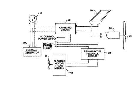
In a more det~ l embodiment of the present invention, as illustrated in Figure
2, the speed control circuit 16 is embodied in a sun speed controller 116 and a ring
speed controller 117. The operation of each of these controllers is determined by the
lo inputs generated through the user control panel 18. As noted above, the electric
motor/L.i-~,x,,,i~sion 12 includes a sun gear motor po~e,i--g a sun gear assembly; a ring
gear motor powering a ring gear assembly; and a tr~n.~mi~sion assembly (all not
shown). The sun speed controller 116 controls the electrical energy fed to the sun
gear motor, thereby controlling the speed and torque of the sun gear motor and its
corresponding sun gear assembly. The ring speed controller 117, on the other hand,
controls the electrical energy fed to the ring gear motor, thereby controlling the speed
and torque of the ring gear motor and its corresponding ring gear and tranxmixsion
assemblies.
The power supply 20 is embodied in a main power supply 120 that supplies the
electrical energy for operating the sun and ring gear motors of the electric
motor/t~ X~ sion~ and a control power supply 121 that powers the sun and ring gear
controllers 116, 117.
The chal~hlg circuit 22 is configured to receive and regulate electrical energy
from not only the electrical input source 24, but also from a conventional llS vol~
heavy-duty outlet 126 and an external generator 127 (i.e., a gasoline-powered
genel~lor). Further, the charging circuit 22 regulates the electrical energy inputted into
each of the main and control power supplies 120,121 for recharging them.
In a separate circuit, the electric motor/tr~n~mi.c~ion 12 is conn~cted to the main
power supply 120 through a regenerative feedback circuit 28 that includes the
CA 022~3226 1998-10-27
Wo 97/40999 PCT/USg7l07556
regel~.ative fee~lbar~ loop 24c shown in Figure 4C. The rege.~ldli~e feedback circuit
28 receives electrical energy from the electric motor/tr~n~mi~sion 12 when it operates
as a gene.dtur (as explained above), and feeds that energy to recharge the main power
supply 120 directly.
Like the charging circuit 22 shown in Figure 7, the regenerative fee~lb~clr
circuit 28 in one embodiment (not shown) can incorporate monitoring circuitry for
monitoring and ~ign~lling which batt~ lics in a bank of batteries need repleni~hment or
repl~ren~nt~ and ~wiLching cir~ itl~y for selectively charging the batteries, in order to
either evenly regulate the charging of the batteries or to charge only the batteries that
lo require charging.
As shown in Figure 3, one embodiment for the user control panel 18, in
accordance with the system of the present invention shown in Figure 2, comprises an
ENABLE switch 181, a direction control device 182, and a speed control device 183.
The physical implementation of all three devices would be embodied in the use ofs switches and variable input level devices as known in the art. For example, ENABLE
switch 181 may be embodied in a conventional Illo~ ,y contact switch, while the
direction control device 182 and the speed control device 183 may be embodied inconventional variable position levers. Both the direction control device 182 and the
speed control device 183 are connected to send corresponding control signals to the sun
speed controller 116 and to the ring speed controller 117.
In the functional implementation of the invention as shown in Figure 2, the
ENABLE switch 181 controls activation of the user control panel 18, for example, by
controlling the connection to the control power supply 121. When the user control
panel 18 is active, the direction control device 182 outputs direction control signals to
both the sun speed controller 116 and the ring speed controller 117 determining
whether the electric motor/tr:~n~mi~.cion 12 will operate and propel the boat/vessel in
a forward (setting F) or reverse (setting R) direction, or remain in an idle or neutral
(setting N) state.
CA 022~3226 1998-10-27
Wo 97/40999 PCT/USg7/07556
The speed control device 183 outputs speed control signals to the sun speed
controller 116 and the ring speed controller 117, d~e~ g the speed and torque
output levels of the sun gear motor and the ring gear motor. As illustrated in Figure
3, the speed control device 183 is structured to vary between m~ximllm (setting MAX)
s and Illillillllllll (setting MIN) output levels of the motors, and to output speed control
signals corresponding to a selected output level. One technique for implementing the
speed control device 183, as well as the direction control device 182, involves the use
of a microprocessor-controlled circuit (not shown) as known in the art. The positions
of the two control devices are tr~n~l~ted by the microprocessor-controlled circuit into
lo the corresponding direction and speed control signals. Those direction and speed
control signals are then inputted into the sun speed controller 116 and the ring speed
controller 117. The sun speed controller 116 and the ring speed controller 117 in turn
use the control signals to regulate the electric energy fed to the electric
motor/tr:m.cmi~.cion 12.
An alternative technique for implementing the direction and speed control
devices 182, 183 involves structuring the control devices to output analog or digital
signals indicative of their respective positions (i.e., F versus R, MAX versus MIN).
The ~ul~ull~d signals from the control devices are then inputted into each of the sun
speed controller 116 and the ring speed controller 117. In this implementation, both
the sun speed controller 116 and the ring speed controller 117 are implemented using
~icloplocessor-controlled circuits (not shown). The sun speed controller 116 and the
ring speed controller 117 translate the outputted signals from the user control panel 18,
and respectively regulate the operation of the electric motor/tr~n~mi~sion 12.
A further alternative technique for imple"~.,li"g the direction and speed contro}
devices 182, 183 of the user control panel 18, as well as the sun speed and ring speed
controllers 116, 117, involves the use of microprocessor-controlled circuits in the user
control panel 18 and in each of the sun speed and ring speed controllers 116, 117. In
each of the above-described techniques, the structure and operation of the
microprocessor-controlled circuit is in accordance with conventional controller circuits
used in similar applications as known in the art.
-
CA 022~3226 1998-10-27
wo 97/40999 PCT/USg7/07556
In operation, to move the boat/vessel r~"vvard, for example, the direction
control device 182 is set in the "forward" position (setting F) while speed control
device 183 is positioned at a relatively low setting (i.e., at or near setting MIN). In
this configuration, the direction control device signals the sun speed controller 116 to
s configure the electric motor/l~ ---icsion 12 with the sun gear assembly locked rigidly
in p~ace, while allowing the ring gear assembly to be rotated in the desired direction
to propel the boat/vessel forward.
Sim--lt~nPously, the speed control device 183 c-l"",-,l,-ir~tçs with the ring speed
controller 117 to direct the electric motor/trancmicsion 12 to rotate the ring gear
0 assembly at a relatively slow rotational velocity. In this l.lamler, motor tr~n~micsion
12 delivers a Illi~ -"--- amount of torque to the propeller 14, thereby rotating the
propeller 14 at a relatively slow rotational velocity.
To propel the boat/vessel at higher velocities, the propeller 14 must be rotatedat a higher rotational velocity and the electric motor/tr~ncmi.csion 12 must produce a
greater amount of torque. To do so, speed control device 183 is set at or near amidway point between the maximum output (setting MAX) and minimnm output or idlesettings (setting MIN), thereby directing the sun speed controller 116 to rotate the sun
gear assembly in a direction identical to the ring gear assembly's direction. The sun
gear assembly rotates at a rotational velocity less than ring gear assembly's rotational
speed when the speed control device 183 is positioned between the midway position
and the maximum output setting (MAX). As a result, the electric motor/tr~ncmi.csion
12 produces more torque than when the sun gear assembly is rigidly fixed, thereby
propelling the boat/vessel faster.
The boat/vessel is propelled forward at a maximum speed when the electric
2s motor/tr~ncmiccion 12 delivers a maximum amount of torque to the propeller 14.
Maximum torque is produced when the speed control device 183 is positioned at the
maximum setting (MAX). At that setting. the speed control device 183 directs the sun
speed controller 116 to rotate the sun gear assembly in the same direction and at the
same rotational velocity as the ring gear assembly.
11
CA 022~3226 1998-10-27
W O 97/40999 PCTrUS97/07556
To propel the boat/vessel in the reverse direction, the direction control device182 is positioned in the reverse setting (R). The sun speed controller 116 and the ring
speed controller 117 direct the electric motor/tr~n~mi.ccion 12 to rotate the sun gear
assembly and ring gear assembly in directions opposite to those ~ cucsed above. The
speed of the boat's/vessel's leal~drd moY~ nl is controlled in the same fashion as
that ~ cllcsed above.
Further, the direction control device 182 can be set at the "neutral" position
(setting N) at which propeller 14 is not being rotated in either direction by the sun gear
motor or the ring gear motor. In this position, sun gear motor and ring gear motor
o remain coupled with the propeller 14, whereby rotation of the propeller 14 due to the
movement of the water will operate the electric motor/tran~mi~sion as a generator.
Consequently, electric energy ~ eldted by the electric motor/tr~n~mi~sion 12 will be
fed through the regenerative fee~b~ck circuit 28 to recharge the main power supply.
As shown in Figure 5, the electrical input source 24 (See Figures 1 and 2) can
be embodied in more than a single type of electrical energy generating system. Here,
for example, the electrical input source 24 consists of a solar panel 24a connected and
operating in parallel with a wind-powered generator 24b. Also, a regenerative
feedb~ck circuit embodying a water- or wave-powered generator 24c can be included.
In accordance with the embodiment illustrated in Figure 2, the regenerative feedback
circuit 28 is connPcted directly to the main power supply 120, since the regel~ld~ e
fee~lbacl~ circuit 28 can include, as noted above, monitoring circuitry for monitoring
and ~i~n~lling which ba~l~lies in a bank of batteries need repleni~hmPnt or repl~reni Pnt,
and ~wilchhlg ci~cuilly for selectively charging the batteries. When the charging
circuit 22 and the regenerative fee(lb~ck circuit 28 are designed as independent circuits,
as illustrated in Figure 5, a manual switching circuit ~not shown) can be incorporated
that allows a user to select which of the two circuits will regenerate the main power
supply 120.
Alternatively, a system as shown in Figure 6 may be used where an energy
input and load management circuit 200 is used to control the regenerating of the main
power supply 120 and the control power supply 121. In essence, the load management
12
CA 022~3226 1998-10-27
wo 97/40999 PCT/US97/07556
circuit 200 incorporates the functions of the charging circuit 22 and the regenerative
feedback circuit together.
As shown in Figure 8, one embodiment of the load management circuit 200
includes a control circuit 201, a first monitoring circuit 202 for monitoring and
~i~n~llin~ which bal~.ies in a bank of batteries 20a need repleni~hmPnt or repl~em~nt,
a first switching circuit 203 for selectively charging the batteries, a second monitoring
circuit 204 for mn~ lg which of the energy input devices is in~ g or is capable
of inputting energy, and a second switching circuit 205 for switching between energy
input devices. The control circuit 201 is a microprocessor-based device that controls
o the operation of the other circuits.
In operation, the first monitoring circuit 202 monitors which batteries in a bank
of batteries need repleni~hm~ont or replacement, and signals the control circuit 201
accordingly. The second monitoring circuit 204 monitors which of the energy input
devices can provide energy. For example, the second monitoring circuit 204 detects
which of the solar panel 24a (i.e., if there is available sl-nlight), the wind-powered
generator 24b (i.e., sufficiently strong air ~;ullellL~ are rotating the windmill-type
device 25), or the electric motor/tr~n.cmi~sion 12 (i.e., when the electric motor/
tr~n~mi.~sion 12 is not being used as a motor) is generating electrical energy. The
second monitoring circuit 204 can also detect whether the system is connected to an
external energy source (i.e., a 115-volt outlet at a dock), or to an external generator
27. The second monitoring circuit 204 then signals the control circuit 201 as to which
energy input devices and other energy sources are available.
The first switching circuit 203 is controlled by the control circuit 201 and
selectively switches between the energy storage cells in the main and control power
supplies 120, 121. For example, with a bank of batteries, the first switching circuit
203 selectively connects with the batteries that need recharging. In one variation of the
energy input and load management circuit 200, the first monitoring circuit 202
measures the energy levels of the individual batteries, and the control circuit 201 uses
those mea~u~ ell~ to dtt~lllline the order and priority for recharging or to determine
and thereby intlic~te which of the batteries needs replacement.
13
.
CA 022~3226 1998-10-27
wo 97/40999 PCT/USg7/07556
The second swil~hing eircuit 205 is also eontrolled by the eontrol eireuit 201
and seleetively switehes bc~wcell the dirr~,lc,l~ energy input deviees and energy sourees
as they become available, get conn~etecl or disconnPcted or rliminich in providing
energy. For example, while the boatlvessel is anchored offshore, the energy input and
s load management eircuit 200 ean be r~chargi,lg the power supplies 120, 121. If
s~lnlight is available, the solar panel 24a ~lltom~tir~lly gene,~l~s eleetrieity. The
seeond moniloling eireuit 204 detects the y~sellce of electrical energy, and the second
switching eireuit 205, under eontrol of the eontrol eireuit 201, routes the energy
aceordingly to the first switehing circuit 203 to lcchal~e the power supplies 120, 121.
lo If eloud eover develops, thereby ~3iminiching the snnlight, but the offshore winds start
to pick up, the second monitoring 204 deteets the ehanges in the energy input deviees.
The eontrol eircuit 201 then controls the second ~wi~;hing eircuit 205 to switch routing
energy from the solar panel 24a to routing energy from the wind-powered generator
24b.
As a eonsequence, the energy input and load management cireuit 200 maximizes
the usage of the dirr~ energy input devices and m~int~inc the power supplies 120,
121 at uyLil~ ll operational levels.
Although the present invention has been fully described in connection with the
yner~llcd embodiment thereof with reference to the accompanying drawings, it is to be
noted that various changes and modifications are appalellL to those skilled in the art.
For example, the auxiliary propulsion system of the present invention can be used as
the primary propulsion system for a boat, ship or vessel with little or no mo~lifir~tion
from the embo-limPrltc disclosed above. In addition, instead of a conventional propeller
14, the electrie motor/tr~n.cmicsion ean be connrcted to a turbine, a paddlewheel or
2s other similar deviee that ean provide loeomotion through water, while being usable as
a generator when water is forced to flow through it. These and other changes andmodifieations are to be understood as included within the scope of the present invention
as defined by the appended claims, unless they depart thelcfio,ll.
14