Note: Descriptions are shown in the official language in which they were submitted.
CA 022~3318 1998-10-28
lh~ Sw d~h P~ CI / Fi ~ 7 / 0~! r
hl1am~icnal App~cat;o~
- 1997 -11- 2 7
MULTI-LAYER REINFORCED AND STABILIZED CABLE CONSTRUCTION
The invention relates to a multi-layer reinforced and stabilized cable
construction comprising a core element and a non-metallic sheathing element
5 with barrier and protective layers and two or more reinforcement layers.
Cable constructions of the above-mentioned type are rather well
known at present in connection with various cables, e.g. fibre optic cables. Theexisting non-metallic fibre optic cable constructions require several process
steps, some of which may be very slow. Expensive reinforcements added
10 separately to the constructions may require the use of additives to achieve
suffficient adhesion or waterproofness, which further retards the manufacturing
process. In order to improve the thermal stability of the cable construction, i.e.
to reduce the thermal compression, it is often also necessary to use rod-like
reinforcing elements. The use of such elements results in certain, not always
15 positive, properties of the cable: flexural stiffness, greater dimensions, high
price, etc. It is particularly diffficult to use such separate composite rods in so-
called central tube constructions, in which the rods must be mounted on the
outer circumference of the core, and there must be at least two of them for
reasons of symmetry.
If the cable is to provide mechanical protection against rodents and
termites and resistance to oil and chemicals, and/or to have barrier properties
against moisture and gases, it is necessary to use expensive semi-finished
products, which must be processed in separate, often complicated process
steps. This complicates the construction and increases the costs of the
25 product.
The object of the present invention is to provide a cable
construction by which the above-mentioned drawbacks of the prior art can be
eliminated. This is achieved with the cable construction of the invention. The
cable construction of the invention is characterized in that, to control the
30 mechanical and barrier properties of the cable, the barrier and protective
layers and/or the reinforcement layers are oriented in a controlled manner at
different angles by means of fibrous reinforcements or lamellar barriers.
An advantage of the invention over the prior art is, for example, that
the mechanical and barrier properties of the cable can be adjusted extremely
35 advantageously according to the need. This is because the invention is simple,
and the manufacture can take place in one extrusion step, whereby the costs
~ SH~r
CA 022~3318 1998-10-28
~ 7/ Cu _ ~ -
1997 -1 1- 2 7
will be low. A further advantage of the invention is that it makes it possible to
provide a construction which can be re-melted and is completely recyclable.
In the following, the invention will be described in greater detail by
means of the examples illustrated in the accompanying drawings, in which
Figure 1 is a general view of a cable construction of the prior art,
Figure 2 is a general cross-section of a cable sheathing of the prior
art,
Figures 3 to 6 show examples of fibre optic cable constructions of
the invention, and
Figure 7 shows an example of a cable of the invention, provided
with a metal core.
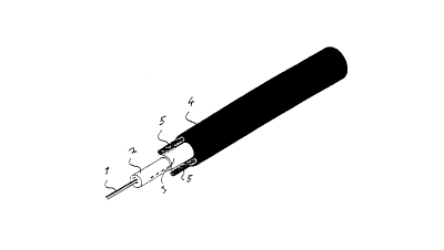
Figure 1 is a general view of a cable construction of the prior art. In
Figure 1, a core element is indicated by reference numeral 1- 2. The core
element may consist of optical fibres 1 and a secondary coating 2, for
15 example. The layers formed by the sheathing are indicated by numerals 3 and
4. Rod-like reinforcing elements are denoted by reference numeral 5. For
reasons of symmetry, there are two rod-like reinforcing elements 5, and they
are mounted on the outer circumference of the cable, as stated above.
The cable construction of Figure 1 is typically produced by extruding
20 functional layers on top of the secondary coating 2. In the example of Figure 1,
the functional layers are indicated by reference numerals 3 - 4. The extrusion
is typically performed by a conventional crosshead die. One of the drawbacks
of this technology is the weld lines that are formed in the layers. The weld lines
have a detrimental effect on the properties of the cable, since they cause
25 points of discontinuity in the layers, and the properties of the layers at these
points are different from what they are at the other points of the layers. The
points of discontinuity can be seen in Figure 2, which shows a cross-section of
a cable construction. The points of discontinuity are indicated in Figure 2 by
arrows N.
The invention thus relates to a cable construction by which the
drawbacks of the prior art described above can be eliminated. According to the
basic idea of the invention, it is essential for the control of the mechanical and
barrier properties of the cable that the barrier and protective layers and/or the
reinforcing layers are oriented in a controlled manner at different angles by
35 means of fibrous reinforcements or lamellar barriers. The characteristics of the
cable of the invention include tensile strength typical of non-metallic cables,
AMENDED SHEET
CA 022~3318 1998-10-28
?~T/ Fl 97/0026
1997 -11- 2 7
dimensional stability over a wide temperature range and in the event of
sudden fluctuations of temperature, and firmness and flexibility of the
construction. A further characteristic of the invention is that the multi-layer
structure can be manufactured in a controlled manner in one extrusion step.
The reinforcing layer which is extruded on top of the cable core or
correspondingly on the so-called intermediate sheathing and which stabilizes
the cable construction consists, for example, of a thermoplastic polymer, such
as polyolefin, polyester, polyamide or the like, reinforced with solid fibres, such
as glass, carbon, boron, aramid, polyolefin or corresponding fibres.
10 Alternatively, the reinforcement layer may be made of a thermotropic main-
chain liquid crystalline polymer (LCP) or of a mixture of such a polymer and a
conventional thermoplastic. In addition to conventional thermoplastics,
thermoplastics that can be easily oriented and/or crosslinked either during the
extrusion or thereafter are particularly preferred. Liquid crystalline polymers of
15 this type are free-flowing in the molten state and can be processed in the
same way as thermoplastics. On account of the internal organization which is
typical for the LCP material, a composite-like fibre structure is formed in situwhen the melt solidifies. Fibrillation of the liquid crystalline polymer thus takes
place during the extrusion process. A particularly preferred screw geometry for
20 obtaining radial orientation du!ing the process is disclosed in applications
PCT/FI96/00261 and Fl 964988. In the case of liquid crystalline polymers or
mixtures thereof, it is advantageous during the processing to aim at a high
draw-down ratio, which results in a high degree of fibrillation. It is thereforepreferable to provide as many thin LCP reinforcement layers as possible
25 instead of one or two thicker layers. In this case, the draw-down ratio can be
kept high, and the fibrillation takes place efficiently throughout the layer.
Some of the reinforcing layers can be formed by thermoplastic
composites reinforced with continuous fibres. In these embodiments, fully
continuous glass or aramid fibres or corresponding fibres are impregnated with
30 a conventional thermoplastic or adhesion polymer. Oriented PE and PP fibres
have extremely good strength properties; their use for this purpose has been
limited by the relatively low crystallite melting point. On account of the low
melting point, the high extrusion temperature required during the processing
destroys the orientation and strength provided in the fibre. It has been
35 surprisingly found that even with relatively low radiation levels, oriented PE
fibres can be crosslinked in such a way that the orientation is more permanent;
AMENDED SHEET
.. . . . . ..
CA 022~3318 1998-10-28
~ 7/ ~0
1997-11- 2 7
thus the time that the fibre resists heat without losing more than half of its
original strength becomes crucially longer. Alternatively, it is possible to usematerials which have been crosslinked first and oriented to fibres only after
that. It is also possible to use chemically crosslinked polyethylenes. In addition
5 to price, the oriented and crosslinked fibre structure has one significant
mechanical advantage. It has been unexpectedly found that, during the
process, the surface of the fibre partly softens and adheres to the surrounding
plastic matrix, while the mechanical strength still remains on a high level. Such
good adhesion, which is very difficult to achieve with aramid fibres, for
10 example, ensures good impact strength among other things. In addition, pure
polyethylene structure ensures good electrical properties. In the case of the
preferred cable construction of the invention, the manufacture of such a
reinforcement layer can be combined with the actual cable extrusion by on-line
impregnating continuous fibres with thermoplastic matrix. In fibre optic cable
15 constructions, the reinforcement layer described above can form the so-called secondary coating, i.e. the layer protecting the optical fibres.
As stated above, it is an essential feature of the invention that the
fibres of each reinforcement layer, protective layer, or barrier layer have a
certain controlled helical rotating orientation angle in relation to the longitudinal
20 axis of the cable. An embodiment of the invention is shown generally in Figure
3. The core element is indicated in Figure 3 by reference numerals 1 and 11.
Layers mounted on top of the core element and provided with reinforcements
are denoted by reference numerals 12 and 13. The surface layer of the
sheathing is indicated by numeral 14. The different orientation angles of the
25 reinforcing fibres in layers 12 and 13 are clearly shown in Figure 3.
The orientation direction of the fibres may be parallel in all the
layers or in some of the layers, but the orientation angle is different. Thus the
tensile and flexural properties of each layer can be adjusted in a controlled
manner. In the layer that is closest to the centre of the cable, i.e. the first
30 reinforcement layer, it is advantageous to employ fibres that are substantially
parallel to the longitudinal axis of the cable, i.e. fibres whose orientation angle
is small. The rotation of the fibres is achieved, for example, with a rotating
mandrel, through which fibres pass as disclosed in Fl 964989. A
corresponding rotating mandrel can be combined with the machine solution
35 disclosed in PCT/FI96/00261, whereby extremely efficient helical molecular
orientation is achieved in addition to continuous fibres. In this case, the fibrous
AMENDED SHEET
. ~ . . ... ... ... .
CA 022~3318 1998-10-28
JC~ i ?,
1997~ 2 7
reinforcements increase the tensile strength of the cable as much as possible,
whereas they reduce the flexibility of the cable as little as possible, i.e. have
the smallest possible stiffening effect, on account of the short distance from
the centre. Correspondingly, the orientation angles of the fibres in the outer
5 reinforcement or protective layers are preferably greater in order for the fibres
to reduce the flexibility of the cable to a smaller extent and to increase the
radial compressive strength of the cable to a greater extent. Such an
arrangement is shown in Figure 3. In addition, a greater orientation angle of
the fibres in the outer layers enhances the protective effect against rodents.
The fibrous reinforcement layers, which are oriented at different
angles, and which in the transverse direction are brittle as such and have low
tensile strength, reinforce each other, since the cross-plied fibres of the
different layers support one another in the event of transverse stresses. The
multi-layer lamellar construction consisting of fibres oriented in a controlled
15 manner thus forms a kind of network structure, in which the mechanical
properties of the entire reinforcement can be controlled by adjusting and
controlling the orientation angles of the fibres in the different layers.
The so-called barrier layer protecting the cable core prevents
moisture and possibly even hydrogen from penetrating into the cable core.
20 Such a layer may preferably consist of a thermotropic main-chain liquid
crystalline polymer (LCP), polyolefin (mainly high-density polyethylene HDPE
or polypropylene PP), cyclic olefin copolymer (COC) or a corresponding
thermoplastic exhibiting good moisture barrier properties. In the symmetrical
construction of the invention, with no weld lines, the barrier properties are
25 achieved with a very thin layer of the above-mentioned plastics. The layer
thickness is typically about 50 to 100,um, depending on the material. The
sy"""el,ical homogeneous structure ensures that even a thin layer is
mechanically strong enough to remain undamaged and operative when the
cable is subjected to mechanical stresses. Particularly when the barrier
30 material is liquid crystalline polymer, the required reinforcement, i.e. the tensile
and compressive strength, can also be achieved with one layer (lamellar
structure). On the other hand, using mixtures of liquid crystalline polymers andthermoplastics in separate reinforcement layers such that the orientation
directions of the LCP fibres or lamellas cross each other provides not only
35 excellent mechanical properties but also moisture barrier properties. Such anembodiment is shown in Figure 4. In Figure 4, the core element is indicated by
A~IIEI~ED SHEET
CA 022~3318 1998-10-28
l ?7~jO
1997~ 2 7
reference numeral 21. Layers provided with LCP fibres or lamellas are
indicated by numerals 22 and 23. The surface layer is denoted by numeral 24.
The cross-plied orientation directions of the LCP fibres or lamellas appear
clearly from Figure 4. Since the liquid crystalline polymers that can be used
5 are very aromatic in their chemical composition and form a strictly ordered
structure in the solid state, they provide particularly good protection even
against smaller gas molecules. A protective layer against hydrogen, in
particular, is extremely important for optical fibres; in non-metallic
constructions such a layer is provided by liquid crystalline polymers.
In a multi-layer construction consisting of many different
thermoplastics, the adhesion between functional layers (i.e. barrier layers,
reinforcement layer, etc.) is particularly important. In the construction of theinvention, thin adhesion layers can, if necessary, be formed between thicker
functional layers. Since adhesion polymers are soft, it is important to keep
15 their layers as thin as possible. Adhesion layers comprising a functional
feature are particularly preferred. A semiconducting adhesion layer, for
example, protects electrically an optical cable mounted in it. A symmetrical
construction with no weld lines makes it possible to have thin and even layers.
In the cable constructions of the invention, the degree of bonding between the
20 different reinforcement layers can be adjusted by various thin adhesion or
buffer layers, whereby the interaction between the layers can be either
increased or decreased according to the need. The components which
improve adhesion or elasticity may also be mixed into the reinforcement layers
themselves. Another alternative is that the fibrous segments in the same
25 reinforcement layer alternate with more elastic polymer segments in the
circumferential direction, whereby a good balance is achieved between
longitudinal reinforcement and flexibility. Such an embodiment is shown in
Figure 5. In Figure 5, the core element is indicated by reference numerals 1
and 31. Reference numeral 32 indicates a reinforcement layer which is divided
30 into fibrous reinforcement segments 32a and more elastic filler portions 32b.Numeral 33 denotes the surface layer of the cable. In yet another preferred
embodiment, the elastic portion or separate buffer layer is formed by a foamed
polymer which is in immediate contact with the fibrous reinforcements for
controlling the flexural and compressive properties of the cable. Such a layer
35 is typically formed by a foamed polyolefin with a density of 50 to 200 kg/m3.
AMENDED SHEET
CA 022~3318 1998-10-28
r ~ T /
1997 -11- 2 7
As stated above, the construction of the invention can preferably be
manufactured in one extrusion step, whereby no intermediate steps such as
reeling are required. In addition, it is extremely important that the flowing
direction of the molten material is parallel to the cable core and that the molten
5 mass flow does not branch off at any stage, whereby the formation of a so-
called weld line is avoided. It is generally known that in plastic products a weld
line is a mechanically weak point from which crazing often begins. A weld line
is considerably weaker than other parts of a product. A uniform mass flow
allows seamless and homogeneous layers to be formed, whereby the desired
10 properties can be achieved with thinner layers than usual. Smaller
consumption of material is economically significant, since the best polymers
used in reinforcing and barrier layers are known to be rather expensive. The
invention thus renders it possible to manufacture multi-layer cable
constructions which are both technically and economically more advantageous
15 than constructions of the prior art.
The multi-layer constructions of the invention can, in principle, be
manufactured with a conventional crosshead die comprising rotating nozzle
tools. However, in practice it is very difficult to manufacture multi-layer
constructions in a controlled manner with such technology. Most preferably,
20 multi-layer constructions of the invention, with no weld lines, are manufactured
with a so-called cone extruder, disclosed for example in EP 0 422 042 B1.
Although the invention has been described above mainly by means
of various embodiments of an optical cable, it should be noted that the
invention can also be applied in the case of cables in which the core consists
25 of metal conductors.
In the following, a few illustrative examples will be given of solutions
i"~,cle",en~ed according to the invention. The examples illustrated are four-
layer constructions, but it will be obvious that the number of the layers may
also be different, depending on the structure of the multi-layer extruder; if
30 necessary, there may be even more than four layers. The layers are
numbered from the innermost to the outermost.
A. A separate optical cable core (PBT, optical fibres, gel) or a metal
conductor on top of which a multi-layer construction (functional portions and
35 outer sheathing) is extruded.
AMENGED SHEET
CA 022~3318 1998-10-28
PCTI Fl ~37/ 00~6 '
1997 -11- 2 7
1. - adhesion polymer
- LCP or LCP blend, orientation + 45~ (reinforcement)
- LCP or LCP blend, orientation - 45~ (reinforcement)
- outer sheathing (e.g. PE)
5 the middlemost layers together form a barrier layer.
2. - adhesion polymer
- LCP, LCP mixture or fibre composite, orientation + 45~
- LCP or LCP mixture, thin laminar layer (barrier)
- outer sheathing (e.g. PE)
10 the first LCP layer or the like is the actual reinforcement.
Special construction (continuous fibre as reinforcement, on-line melt
impregnation).
- if necessary, adhesion polymer (hot melt) can be applied on top of
15 a PBT tube by a melt pump immediately before the coextrusion step.
1. - on-line impregnated continuous glass fibre, mounted at a suitable
angle around a PBT tube
- polyolefin as matrix (may contain functionalized
polyolefin, adhesion)
- or adhesion polymer as matrix (good adhesion on both
surfaces)
- thin, even layer of HDPE, COC, LCP or PO/LCP blend (barrier)
- adhesion polymer
- outer sheathing (e.g. PE)
2. (- adhesion polymer)
- thin LCP or LCP blend (moisture barrier)
- on-line impregnated continuous glass fibre, mounted at a suitable
30 angle around a PBT tube (polyolefin as matrix)
(- adhesion polymer)
- outer sheathing (polyolefin)
B. Secondary coating made in the same step
AM~NDED SHE~T
.
CA 022~3318 1998-10-28
, ?- / ~ f'
1997 -l l- 2 7
1. - LCP blend or fibre composite (incl. optical fibres, gel) as protectivematerial 41
- reinforcing structure (axial orientation)
- thin adhesion layer 42
- actual reinforcement layer (LCP or fibre composite, oblique
orientation 43
- outer sheathing (e.g. PE) 44
This embodiment is shown in Figure 6. Numerals 41 to 44 refer to Figure 6.
10 2. - thermoplastic (incl. optical fibres, gel) as protective material
- ethylene/propylene copolymer (suitable gel)
or PBT
- or: COC (moisture barrier at the same time)
- thin adhesion layer
- actual reinforcement layer (PO/fibre or PO/LCP mixture), oblique
orientation
- outer sheathing (e.g. PE)
C. Mere multi-layer sheathing construction, core Spiral Space,
20 twisted construction or metal conductor
1. - adhesion polymer
- intermediate sheathing PE
- adhesion polymer
- outer sheathing PA 12 (e.g. termite protection, abrasion
resistance)
2. Fire-resistant sheathing
- adhesion polymer
- barrier layer (HDPE, COC, LCP or PO/LCP mixture) and/or
reinforcement layer (cf. above)
- adhesion polymer (not necessary)
- HFFR compound
35 3. Rodent-resistant sheathing
- adhesion plastic 52
AMENDED SHEET
. CA 022~3318 1998-10-28
~CT/ ,-l ?, J, o
1997-11- 2 7
- polyolefin/glass fibre 53
- polyolefin/large amount of glass fibre (short-cut fibre or on-line
impregnated continuous fibre) 54. Large transverse orientation angle.
- thin HDPE or PA 12 skin 55
Such an embodiment is shown in Figure 7. Reference numeral 51
indicates a core element consisting of metal conductors. Numerals 52 to 55
denote the layers listed above. Numerals 52 to 55 are also indicated in the
layer description of the example above.
The embodiments described above are not intended to limit the
10 invention in any way, but the invention can be modified fully freely within the
scope of the appended claims. It will thus be clear that the cable construction
of the invention or its details need not be precisely as shown in the drawings,
but other solutions are also possible.
M~ENDED SHEEI
. . . , ~ , .