Note: Descriptions are shown in the official language in which they were submitted.
CA 022~370~ 1998-10-23
WO 97/41786 PCT/US97/03537
UVUI,~, TONSIL, AnF,NOID ANI) SINUS TJ~SUE TREATMF,NT
DEVICE, AND METHOD
S RELATIONSHIP TO COPENDING APPEICATIONS
The present application is a continuation of Prior Application,
~ Application No. 08/311,097 filed September 23, 1995, which is a continuation in
part of copending application Serial No. 07/929,638 filed August 12, 1992,
Serial No. 08/012,370 filed February 2, 1993 (Patent No. 5,370,675), Serial No.
08/062,364, filed May 13, 1993, Serial No. 08/061,647, filed May 13, 1993,
Serial No. 08/061,072 filed May 14, 1993 (Patent No. 5,385,544) and Serial No.
08/239,658 filed May 9, 1994. The entire contents of each of the above
applications being hereby incorporated by reference.
FIELD OF THE INVENTION
This invention relates generally to a method and device for the treatment
of the uvula, tonsils, adenoids and sinus tissue. In particular, the invention
relates to a RF ablative device and method for treatment of the uvula, tonsils,
adenoids, or sinus tissue.
BACKGROUND OF T~E INVENTION
Tre~tment of cellular tissues usually requires direct contact of target
tissue with a medical instrument, usually by surgical procedures exposing both
the target and intervening tissue to substantial trauma. Often, precise placement
of a treatment probe is difficult because of the location of a target tissue in the
body or the proximity of the target tissue to easily damaged, critical body
organs, nerves, or other components.
Destruction of cellular tissues i71 si~2l has been used in the treatment of
many diseases and medical conditions alone or as an adjunct to surgical removal
procedures. It is often less traumatic than surgical procedures and may be the
only alternative where other procedures are unsafe. Ablative treatment devices
CA 022~370~ 1998-10-23
WO 97/41786 PCT/US97/03537
have the advantage of using a destructive energy which is rapidly dissipated andreduced to a non-destructive level by conduction and convection forces of
circul~ting fluids and other natural body processes.
Microwave, radio frequency, acoustical (ultrasound), and light energy
(laser) devices, and tissue destructive substances have been used to destroy
m~lign~nt, benign and other types of cells and tissues from a wide variety of
anatomic sites and organs. Tissues treated include isolated carcinoma masses
and, more specifically, organs such as the prostate, gl~nd~ r and stromal
nodules characteristic of benign prostate hyperplasia. These devices typically
include a catheter or cannula which is used to carry a radio frequency electrodeor microwave ~nt~nn~ through a duct to the zone of treatment and apply energy
diffusely through the duct wall into the surrounding tissue in all directions.
The copending applications disclose an ablative medical probe generally
for penetrating body tissues for medical purposes and a radio frequency medical
1 S treatment with optical viewing capabilities.
This RF ablative technology can now be extended to the treatment of
uvulas, tonsils, adenoids and sinuses. Many people suffer from infiamed tonsils
and adenoids. In addition, many people suffer from sinus problems. In the past,
all of these conditions could be treated using surgery. The surgery, however,
caused discomfort to the patient and caused bleeding. In addition, surgery
required a several day stay at a hospital which is quite expensive.
OBJECTS AND SUMMARY OF TEE INVENTION
It is therefore an object of the present invention to provide a method of
treating uvula, tonsil, adenoid and sinus tissue which minimi7.es bleeding and
trauma to surrounding tissues.
It is another object of the present invention to provide a device for
treating uvula, tonsil, adenoid and sinus tissue which has a disposable electrode.
CA 022~370~ 1998-10-23
WO 97/41786 PCT/US97/03S37
It is another object of the present invention to provide a method of
treating uvula, tonsil, adenoid and sinus tissue in which a medical Lle~ n
device is routed through the nasal passages to treat the tissues.
These and other objects of the present invention are provided by a
method for medical ablation of tissue to reduce the size and mass of said tissuehaving the steps of: a) inserting a probe through a body opening and moving the
probe into close proximity to the tissue, the probe having an electrode enclosedwithin an in~ ting sleeve axially moveable thereon and bendable therewith; b)
e~ten~ling said sleeve and said electrode out of said probe and penetrating saidtissue; c) retracting said sleeve from the terminus ofthe electrode to expose a
predetermined electrode area for ablation; and d) applying RF energy to the
tissue surrounding the exposed electrode area to effect ablation of said tissue. A
device for treating tissue is also disclosed.
BRIEF DESCRIPTION OF T~E DRAWINGS
Fig. 1 is a sagittal view of a human head showing the location of the
uvula, the tonsils, the adenoids and the sinus tissues.
Fig. 2 is a front view of a mouth showing the orientation of the uvula and
tonsils.
Fig. 3 is a planar view of a stylet ablation device of this invention.
Fig. 4 is a top view of the handle top plate of the stylet ablation device
shown in Fig. 3.
Fig. 5 is a fr~gm~nt~ry cross-sectional view of the manual control portion
of the handle of the stylet ablation device shown in Fig. 3 taken along the line A-
A in Fig. 3.
Fig. 6 is a fr~p;ment~ry cross-sectional view of the tip of the stylet
ablation device such as that shown in Fig. 3 with the stylet retracted into the tip.
Fig. 7. is a fr~grnçnt~ly cross-sectional view of the tip of the stylet
ablation device shown in Fig. 3 with the electrode and sleeve extended from the
tip.
CA 022=,370=, 1998-10-23
W O 97/41786 PCT~US97tO3537
Fig. 8 is a front view of a patient's mouth wherein an uvula is being
reduced by the ablative method of the present invention.
Fig. 9 is an isometric view of the device of the present invention for
treating uvulas, tonsils, adenoids and sinus tissues.
Fig. 10 is an expanded fragmentary cut-away side view of the probe end
of the device shown in Fig. 9 having a retracted fiber optic, a retracted electrode,
and a steering mech~ni.cm
Fig. 11 is an expanded fr~gmçnt~ry cut-away side view of the probe end
of the device shown in Fig. 9 having an extended fiber optic, an extended
electrode and a steering mechanism.
Fig. 12 is an expanded fragmentary cut-away side view ofthe probe end
of the device shown in Fig. 9 having a bipolar electrode and a fiber optic.
Fig. 13 is an expanded fragmentary cut-away side view of the probe end
of the device shown in Fig. 9 having a hollow electrode and a fiber optic housedwithin the electrode.
Fig. 14 is an expanded fragmentary side view of one embodiment of a
monopolar electrode which is used in the present invention.
Fig. 15 is an expanded fragmentary side view of another embodiment of a
monopolar electrode.
Fig. 16 is an exp~nded fragmentary side view of another embodiment of a
monopolar electrode.
Fig. 17 is a fragmentary expanded cross sectional view of the device
shown in Fig. 9 taken along line A-A.
Fig. 18 is a sagittal view of a human head showing the device of the
present invention having a monopolar pincher electrode being used to treat a
tonsil.
Fig. 19 is a front view of a mouth showing the device of the present
invention being used to treat a pair of tonsils with one monopolar electrode.
Fig. 20 is a sagittal view of the head of a person showing the device of
the present invention being used to treat an enlarged adenoid.
.
CA 022~370~ 1998-10-23
WO 97/41786 PCT/US97/03537
Fig 21 is a sagittal view of a head of a person showing the device of the
present invention being used to treat rear sinus tissue.
Fig. 22 is a sagittal view of a head of a person showing the device of the
present invention being used to treat frontal sinus tissue.
Fig. 23 is a sagittal view of the head of a person showing the device of
the present invention being used to treat the uvula.
DETAILED DESCRIPTION OF THE INVENTION
To understand the device and method of the present invention, a brief
look at the anatomy of a human head is needed. Fig. 1 shows a sagittal view of ahuman head 1. A nose 3 is shown which allows a surgeon access to nasal
passages 13. A mouth 2 is also shown. Through the mouth 2, the palate 4 is
located. At the end of the palate 4, the uvula 6 is located. The uvula 6 can be
accessed either through the mouth 2 or through the nose 3. Located in the
mouth 2 behind the tongue 10 is the tonsils 8. Only one tonsil is shown in this
figure. The nasal passages 1 3 have openings 16 and 18 which lead to the frontalsinus 15 and sphenoidal sinus 17, respectively. In addition, adenoid tissue ! can
also be ~cces~ed through the nasal passages !.
Many problems and diseases can arise within the mouth and nose. For
example, a condition known as tonsillitis (i.e., inflamed tonsils) can occur. Also,
sinl-~iti.c (i.e., inflamed sinus tissues) can also occur. In addition, people develop
inflamed adenoids. A person may also have a uvula which is inflamed or needs
to be reduced to prevent snoring.
In the past, surgical procedures were available to deal with all of these
problems. However, surgery has many risks and causes bleeding. The devices
and methods of the present invention can cure the above health problems and
reduce recovery time and bleeding.
The first embodiment of the present invention is used for reduçin~ uvular
tissue to prevent snoring.
CA 022~370~ 1998-10-23
WO 97/41786 PCT/US97/03537
Fig. 2 shows a front view of a patient's mouth. The cone shaped piece of
tissue which hangs down from the palate in the back of the mouth 2 is called theuvula 6. In addition, for reference, a tongue 10 and a pair of tonsils 8 are shown
in relation to the uvula 6.
Certain patients lie on their backs when sleeping and at certain times may
breathe through their mouth. The movement of the air through the mouth to the
lungs may cause the uvula 6 to vibrate and generate a hard, raspy sound that canbe very loud at times. This sound is often referred to as a snore. The sleeping
patient may not even be aware of snoring until informed by others. In certain
other patients, the uvula 6 is large enough to hang down over the throat,
effectively blocking the flow of air to the lungs. The patient then gasps for air
and possibly wakes up startled and rolls over. Thus, snoring and its problems
can be uncomfortable to the patient and certainly disquieting to the patient's bed
partner as well.
Apart from the physical, external devices used to wake up the patient, or
at least cause the snorer to roll over, there are surgical procedures that can be
performed. A uvulectomy or partial uvulectomy can be performed to remove all
or part of a patient's uvula. Any surgery, however, has its inherent risks, no
matter how fit and healthy the patient may be. Also, the recovery time is
extensive due to the bleeding and suturing that must be performed during the
surgery. In addition, considerable pain and discomfort is caused to the patient.This conventional uvulectomy can be performed by normal scalpel excising or
possibly by use of a strong laser light which is used to destroy part or all of the
uvula tissue.
In order to decrease the pain, discomfort and recovery time of the
patient, radio frequency (RF) or microwave ablative techniques can be used. In
a RF ablative technique, and RF signal from an electrode placed inside the uvulatissue heats the tissue. The cells are heated to a point where the cells burst and
die. In fact, the RF ablative technique causes a small lesion within the uvula
- 6 --
CA 022~370~ 1998-10-23
WO 97/41786 PCT/US97/03537
which is absorbed by the body. Thus, no external bleeding occurs and no
suturing is required. Also, the uvula size is decreased.
The medical ablation method utilized in this invention is uniquely superior
- for localized therapeutic ablation to remove or reduce undesired tissue masses in
uvulas in order to reduce snoring.
To fully understand this method of reducing snoring using ablation, a
description of an ablation device, as disclosed in the copending applications,
follows.
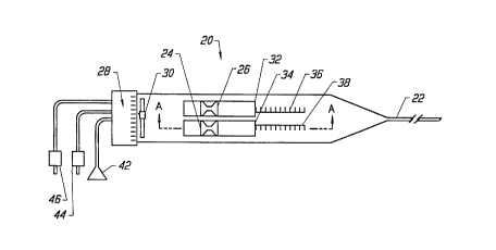
Now, the particular structure of the ablation device will be described with
reference to Figs. 3 and 4. Fig. 3 is a planar view of the ablation device. The
device generally has a handle portion 20 and a delivery tube portion 22. A stylet
sleeve manual control tab 26 and a stylet electrode manual control tab 24 are
mounted for sliding engagement in slots 52 and 54 of a handle top plate 23 (Fig.4). Index markings 28 indicate the relative angle of orientation of the stylet with
respect to a stylet angle indicator 30. The angle indicator 30 can be a bubble in a
curved transparent tube, a weighted pivot dial indicator or an electronic angle
indicator. The position of distal edges 32 and 34 of the tab slides 24 and 26 with
their respective gauge reference strips 36 and 38 show the relative positions of a
stylet electrode 58 and a sleeve 62 shown in Figs. 5 and 6. A more detailed
description of the operation of the tab slides and reference gauge is below.
Connectors for a fiber optic connector 42, a RF power connector 44, and
an ohmic resistance connector 46 extend from the proximal end of the handle
portion 20. The connectors connect the ablative device of the present invention
to a light source, a power source and a detector, respectively.
Fig. 4 is a top view of the handle top plate 23 of the ablation device
shown in Fig. 3. As discussed above, slots 52 and 54 receive the respective tabs24 and 26 for sliding engagement therein. Slot 50 receives the stylet angle
indicator 30. The reference strips 36, 38 are also shown.
CA 022~370~ 1998-10-23
WO 97/41786 PCT/US97103537
Now the structure of the manual tabs 24, 26 will be described. Fig. 5 is a
fr~mçnt~ry cross-sectional side view of the manual control portion of the handleof the stylet ablation device shown in Fig. 3, taken along the line A-A.
Since Fig. 5 is a side view, only the electrode manual control tab 24 is
shown since the sleeve manual control tab 26 is directly behind the electrode
manual control tab 24. The electrode manual control tab 24 is connected to an
electrode connector 56. The electrode connector 56 is in turn connected to an
electrode 58. Although not shown, the electrode 58 would also be electrically
connected to the RF power connector 44 and the ohmic resistance connector 46.
The electrode 58 slides inside of a sleeve 62. The sleeve 62 is connected to a
sleeve connector 60 which in turn is connected to the sleeve manual control tab
26. Thus, the electrode 58 and the sleeve 62 slide relative to each other.
The electrode 58 is preferably made of a flexible, shape memory metal
such as nickel-tit~ni.lm alloy or tempered steel, but may be of any material which
will conduct RF power. The sleeve 62 is preferably made of a highly
conformable ins~ tin~ plastic material such as polyamide. Now, the operation
of the tabs 24, 26 will be described.
Simultaneous forward or rearward movement of both manual control
tabs 24 and 26 cause the sim~lt~neous advancement and retraction of both the
electrode 58 and the sleeve 62. If the electrode manual control tab 24 is moved
alone, then the electrode 58 slides within the sleeve 62 and either retracts into or
extends out of the sleeve 62. Similarly, if only the sleeve manual control tab 26
is moved, the sleeve slides over the electrode. The reference strips 36 and 38
provide reference points for controlled positioning of the electrode manual
control tab 24 and the sleeve manual control tab 26, permitting precise,
independent positioning of both the electrode 58 and the sleeve 62 for controlled
ablation of the uvula as is explained in greater detail below.
Fig. 6 is a cross-sectional view of the tip of the ablation device such as
that shown in Fig. 3 with the stylet retracted into the tip of a needle 74 for initial
insertion to a position accessible with a straight needle. The electrode tip 70 is
CA 022~370~ l998-l0-23
WO 97/41786 PCT/US97/03537
positioned behind the leading sharpened tip 72 of the needle 74. The in~ ting
sleeve tip 76 is positioned just behind the leading edge of the electrode tip 70.
When the electrode 58 is a hollow tube, it can be a conduit for aspiration
~ during treatment, liquid delivery, or in the embodiment shown, a housing for a
fiber optic strand 78. The polished fiber optic tip 80 is positioned behind the
electrode tip 70 to f~ilit~te viewing of the tissue surrounding the electrode tip
during insertion.
Fig. 7 is a cross-sectional view of the tip of the stylet ablation device
shown in Fig. 6 with the electrode and sleeve extended out of the needle 74. this
embodiment shows a needle 74 having a straight configuration. The needle 74
can also be curved. The sleeve 62 is initially in the dotted line position 84 inwhich it covers the electrode. Following insertion of the needle 74 into the body
to the specific site to be ablated, the sleeve 62 is retracted from a selected
portion of the electrode 58 to expose the specific electrode area required to form
a lesion ofthe desired size. The retraction ofthe sleeve 62 is controlled by thesleeve manual control tab 26 as described above.
Fig. 8 shows a front view of a patient's mouth with the RF ablation
device being used to treat an uvula 6 according to the present method. The
patient opens his/her mouth 2 and the tongue is held down. The RF ablative
device with the handle portion 20 is positioned so that the needle 74 is near the
uvula 6. The sleeve 62 and electrode 58 are then extended out of the needle 74
and into the uvula 6. Then, the electrode 58 is exposed by a desired distance,
depending on the amount of the uvula to be ablated. Then, RF or microwave
energy is sent through the electrode 58 and causes an internal lesion within theuvula 6. Once this internal lesion is absorbed by the body, the size of uvula 6
decreases and further snoring problems are elimin~t~d
Now, another embodiment of the present invention will be described
which can be used to treat tonsil tissue, adenoid tissue, sinus tissue and even
uvula tissue. Both a device for treating the tissues and a method of treating the
tissues will be described.
CA 022~370~ 1998-10-23
WO 97/41786 PCT/US97/03537
Fig. 9 shows a planar view of another embodiment of a device for
treating uvula, tonsil, adenoid and sinus tissue. This embodiment has many
similar parts to the first embodiment and like parts will be design~ted by like
numerals. The handle portion 90 is connected to a probe 92, which has a handle
end 94 and a probe end 96. This device has the same tabs 24, 26 which control
an electrode 122 and a sleeve 124. Thus, the operation of the tabs 24, 26 will
not be described here. One difference in this embodiment is that the electrode
122 is disposable so that the tabs 24, 26 and the other controller structure aremounted on a surface 109 which opens up on hinges 110. The controller will be
described below with reference to Fig. 17.
The device of this embodiment also has an impedance meter 112 and a
temperature meter 114 which are incorporated into the handle 90. Both meters
112 and 114 are electrically connected to the RF power supply lead 44 to supply
feedback data. These meters allow the surgeon to accurately control the
tre~tmçnt
The handle 90 also has a trigger 106 and trigger guard 108 which control
the energization of the RF power source. The handle 90 also has a viewing
scope 98 which is connected by a hinge 100 to the handle 90 so that the viewing
scope 98 is adjustable. The viewing scope 98 is connected to the fiber optic 78
which allows the surgeon to view the trc~tmen~ at all times. The handle 90 also
has a horizontal steering control wheel 102 and a vertical steering control wheel
104. The operation of the wheels will be described below with reference to Fig.
10.
Fig. 10 is an expanded cut-away side view of the probe end 96 of the
device shown in Fig. 9. The probe end 96 is not sharpened in this embodiment
so that it can follow a route through the sinus passages without puncturing any
tissue. In this embodiment, any tissue puncturing which is required is done by asharpened tip 126 of the electrode 124. Inside of the probe end 96, there is theelectrode 124 with a sharpened tip 126, a sleeve 122 around the electrode, and afiber optic 78. The sleeve 122 is thin compared to the electrode and located
- 10-
.
CA 022~370~ 1998-10-23
WO 97/41786 PCT/US97/03537
behind the sharpened tip 126 ofthe electrode. Thus, both the electrode 124 and
sleeve 122 together can puncture tissue. Then the sleeve 122 can be retracted toexpose the electrode 124. Also, the sleeve 122 can be retracted prior to tissue
penetration. In addition, the sleeve 122 may be rigidly fixed to the, electrode
124 so that a predeterrnined amount of the electrode 124 is always exposed.
~ The sleeve 122 protects healthy tissue from damage during the treatment. For
example, the sleeve 122 will protect the nasal passages during treatment of the
adenoid tissue. There are also steering members which are connected to both of
the steering wheels 102 and 104 by steering wires. Only the vertical control
wires 118 and 120 and the vertical steering member 116 are shown. It should be
understood that the horizontal steering member and steering wires work in the
same way. The vertical steering member 116 is attached near the handle end 94.
To steer the probe end 96 upwards, the vertical steering wheel 102 is turned andthe upper steering wire 120 is pulled back which causes the flexible steering
member 116 to bend upwards which causes the probe end 96 to bend also.
Similarly, the probe end 96 can be adjusted downwards. It should be noted that
the probe end 96, the electrode 124, the sleeve 122, and the fiber optic 78 are all
somewhat flexible so they can bend. A more detailed description of the steering
mech~ni~m can be found in U.S. Patent Nos. 5,195,968 and 5,254,088 which are
incorporated herein by reference.
Fig. 11 shows the probe end 96 of Fig. 10 with the fiber optic 78, sleeve
122 and electrode 124 extended out ofthe probe end. Fig. 12 shows another
embodiment ofthe device which has bipolar electrodes 128 and 130 in a single
sleeve 132, a fiber optic 78 and steering mech~ni~m.~. Unlike monopolar
electrodes 124 which requires an external grounding plate, the bipolar electrodes
are a first electrode 128 and a second electrode 130. The RF current goes from
the first electrode 128 at a voltage Vl, through the tissue to be treated and
returns through the second electrode 130 at a voltage V2 which is lower than V,.The bipolar electrode can be used with the present invention equally as well as a
monopolar electrode.
CA 022~370~ 1998-10-23
WO 97/41786 PCT/US97/03537
Fig. 13 shows another embodiment of the present invention which has a
hollow monopolar electrode 134. The hollow monopolar electrode 134 is
housed within a sleeve 135 as before. However, inside ofthe hollow monopolar
electrode, a fiber optic 78 is located. As before, a steering mech~ni~m is located
within the probe end 96.
Figs. 14, 15, and 16 show three dif~rellL embodiments of a monopolar
electrode. Fig. 14 is a pincher electrode 138 which is used to treat uvula or
tonsil tissue. When the pincher electrode 138 is within the sleeve, it collapses.
Then, when the sleeve is retracted, the pincher electrode 138 takes the shape
shown. Similarly, Fig. 15 shows another embodiment of a pincher electrode 140.
Fig. 16 shows an electrode 142 having two branches which is used to treat both
tonsils in a single treatment.
Fig. 17 is an expanded cross-sectional view of the device of Fig. 9 taken
along line B-B and shows the hinged surface 109 of the handle which has the
tabs 24, 26. As before, only the electrode tab 24 is shown since the sleeve tab
26 is directly behind the other tab. The electrode tab 24 is connected to an
electrode connector 150. The electrode connector 150 has an electrical contact
146 which electrically connects the disposable electrode 124 to the connector
150. The connector 150 has an electrical trace 144 which electrically connects
the disposable electrode 124 to the RF connector 44 (not shown). The
connector 150 also mechanically connects the disposable electrode 124 to the
electrode tab 24. Similarly, the sleeve tab is connected to a sleeve connector 152
by a sleeve contact 148 which connects to the sleeve 122.
In operation, after the surgeon has guided the probe end 96 to near the
target tissue, a disposable electrode 124 and sleeve 122 are placed within the
device through the hinged surface 109. Once the electrode and sleeve are in
place, the hinged surface 109 is closed and latched. When the hinged surface
109 is closed and latched, the disposable electrode 124 and sleeve 122 are
mechanically and electrically connected to the device. Once the treatment with
the particular electrode is complete, the hinged surface 109 is opened and the
CA 022~370~ 1998-10-23
WO 97/41786 PCT/US97/03537
disposable electrode 124 and sleeve 122 are removed. Then another electrode
can be inserted, or the device may be removed.
The methods of treating tonsil tissue, adenoid tissue, sphenoidal sinus
~ tissues, frontal sinus tissue and uvula tissue will now be described with reference
to Figs. 18-23. Fig. 18 is a sagittal view of a head showing the probe 92 inserted
through the mouth 2 to treat a tonsil 8. The probe end 96 is positioned by the
surgeon near the tonsil 8 and the fiber optic 78, electrode 124 and sleeve 122 are
extended out ofthe probe end 96. Then, the pincher electrode 138 is extended
out of the sleeve 122 and surrounds the tonsil 8. Then, RF current flows
through the electrode 124 and causes an internal lesion within the tonsil 8. If
enough power is supplied to the tonsil 8, all of the tonsil tissue can be elimin~ted.
In both cases, the temperature of the tissue must be raised to above 47~ C for asufficient time to cause death of the tissue cells. No significant bleeding occurs
and the tonsil 8 has been treated.
Similarly, in Fig. 19, the probe is inserted through the mouth 2 and the
branched electrode 142 is used to treat both tonsils simultaneously. The
branched electrode 142 has sharpened tips so that the electrodes can penetrate
the tonsils and generate a RF current within the tonsil. Once again, the RF
current creates a lesion within the tonsils.
Fig. 20 shows the probe inserted through the nose 3 and the nasal
passages 13 to treat adenolds 14. For this treatment, the fiber optic 78 is used to
help the surgeon guide the probe end 96 to a location near the adenoid 14 using
the steering wheels, if neces~ry Once near the adenoid 14, the surgeon extends
the fiber optic 78 and sleeve 122 out towards the adenoid 14. Then, the
electrode 124 is extended out ofthe sleeve 122 until the sharpened tip 126 oftheelectrode penetrates the adenoid 14 to a desired depth. Then, the RF current is
supplied to the tissue by the electrode and a lesion is formed within the adenoid.
Once the body reabsorbs the lesion, the adenoid 14 shrinks or is ~limin~te~
Fig. 21 shows the probe inserted through the nose ! an nasal passages 13
to treat the sphenoidal sinus tissue 17. As before, the surgeon uses the steering
CA 022~370~ l998-l0-23
WO 97/41786 PCT/US97/03537
wheels 102 and 104 to adjust the direction of the probe end 96 and guide the
probe end near the opening 18 of the sphenoidal sinus 17. Then, the fiber optic
78 and sleeve 122 with electrode are extended through the opening 18 into the
sphenoidal sinus. Then, the sharpened tip 126 ofthe electrode 124 is extended
into the sinus tissue and the treatment is completed. Similarly, Fig. 22 shows the
device inserted through the nose 3 and nasal passages 13 to treat the frontal
sinus 15. Once again, the probe end 96 is adjusted using the steering wheels 102and 104 so that it is corrected positioned near the opening 16 of the frontal sinus
15. As before, the fiber optic 78 and sleeve 122 are extended through the
opening 16 and the sharpened tips 126 ofthe electrode 124 is extended into the
tissue and RF power is supplied to treat the tissue.
Fig. 23 shows the probe inserted through the mouth 2 to treat the uvula
6. The probe end 96 is positioned near the uvula 6 and the fiber optic 78 and
sleeve 122 are extended out. Then, the electrode 124 is extended out of the
sleeve and the sharpened tip 126 of the electrode penetrates the uvula and
treatment is carried out.
While the invention has been described with reference to specific
prefel~ed embodiments, it will be understood by those skilled in the art that
various changes may be made and e~uivalents may be substituted for elements
thereof without departing from the true spirit and scope of the invention. In
addition, many modifications may be made without departing from the essential
te~hing~ of the invention.
The foregoing description of a p,efel,ed embodiment of the invention has
been presented for purposes of illustration and description. It is not intended to
be exhaustive or to limit the invention to the precise forms disclosed. Obviously,
many modifications and variations will be appal elll to practitioners skilled in this
art. It is intended that the scope of the invention be defined by the following
claims and their equivalents.
What is claimed is:
- 14-