Note: Descriptions are shown in the official language in which they were submitted.
CA 02253726 1998-10-23
WO 97/39639 PCTIUS97/06572
i
SYSTEM FOR CONTROLLED RIPENING OF FRESH PRODUCE
Field of the Invention
The present invention relates generally to methods and
apparatus for controlled ripening of fresh produce,
particularly fresh fruit like bananas.
Background of the Invention
Bananas and other fresh produce are typically transported
from growing fields to a processing facility where they
are placed in specially designed ripening rooms. These
ripening rooms are provided with insulated, gas-tight
wall and roof panels and include an air handling unit to
control the circulation and temperature of the air within
the ripening room. In this manner, the ripening of the
fresh produce be controlled in accordance with a
predetermined ripening schedule so t:~at the fruit is
properly ripened at the time it is sc:zeduled for delivery
to retail outlets. Ethylene gas may bs dispersed into
the ripening room at preselected times to enable further
control of the ripening of the produce. The use of
ripening rooms thereby facilitates the delivery of
produce to retail outlets without the constraint of
CA 02253726 1998-10-23
WO 97139639 PCT/US97106572
2
having to schedule delivery in accordance with the
natural ripening process of the fruit. Use of ripening
rooms also further obviates problems associated with
accelerations and decelerations of the ripening process
due to changing conditions during the transportation of
the produce.
U.S. Patent Nos. 4,824,685 and 5,373,780 disclose
ripening rooms in which the produce is packed into
unitized shipping modules comprising individual
protective boxes that are block-stacked on pallets. The
palletized produce is placed into ripening rooms having a
floor, ceiling and front, rear and side walls of suitable
dimensions to enclose two spaced rows of the palletized
produce. The two rows are spaced apart from one another
to define an interstitial volume between the rows.
Sufficient spacing is also provided between the
palletized produce and the ceiling and walls of tre
chamber to define an airspace around and above the
produce.
A tarp is placed over the top and one end of the spacing
between the two rows of palletized produce to ger_erally
seal off the interstitial volume from the airspace around
and above the produce. Exhaust fans are arranged in a
sealed relation at the opposite end of the spacing
between the rows to withdraw air from the interstitial
volume and thereby create a pressure differential between
CA 02253726 2004-11-10
50501-2
3
the tarp sealed interstitial volume and the airspace above
and around the produce. Air is introduced into the airspace
by an air handling unit. The air is forced by the pressure
differential between the airspace and the low pressure
interstitial volume to flow through openings in the sides of
the boxes, circulate around the produce contained therein,
and flow into the low pressure interstitial volume to be
exhausted by the fans. In this manner, a forced air
circulation flows throughout the produce load in the
chamber. The temperature and flow rate of the air
introduced into the chamber by the air handling unit can be
varied to control the ripening rate of the produce.
Objects and Summary of the Invention
One object of embodiments of the present invention
is to provide a ripening room with temperature controlled
airflow that maintains produce kept therein at generally
uniform temperatures, that is, it minimizes temperature
variations throughout the produce resulting from the
temperature controlled airflow.
Another object of embodiments of the invention is
to provide a ripening room that, when either fully or
partially loaded, will include airspaces that can be quickly
and easily enclosed to form high and low pressure plena to
facilitate air flow through the produce.
A further object of embodiments of the invention
is to provide a ripening room that can be conveniently
ventilated to periodically replace air used in the room.
According to an aspect of the present invention,
there is provided an apparatus for controlled ripening of
produce comprising: a chamber defined by a ceiling, a
floor, and a plurality of walls connecting the ceiling and
CA 02253726 2004-11-10
50501-2
4
the floor. The chamber is configured to receive two rows of
produce that are spaced apart from each other to define an
interstitial volume therebetween. Each row of produce is
proximate and spaced apart from one of the walls to define a
side airspace therebetween. The chamber also includes an
air control system for transferring air between the side
airspaces and the interstitial volume and controlling the
temperature of the air. The apparatus also includes means
for inhibiting airflow between said side airspaces and said
interstitial volume except for airflow through said air
control system and through said produce, wherein said air
control system includes means for transferring air from said
interstitial volume to said side airspaces during one time
period to form a low pressure plenum in said interstitial
Z5 volume and high pressure plena in said side airspaces such
that the pressure differential between the low and high
pressure plena forces airflow from said side airspaces to
said interstitial volume through said produce, and wherein
said air control system also includes means for transferring
air from said side airspaces to said interstitial volume
during another time period to form low pressure plena in
said side airspaces and a high pressure plenum in said
interstitial volume such that the pressure differential
between the low and high pressure plena forces airflow from
said interstitial volume to said side airspaces through said
produce.
The side airspaces and the interstitial volume are
generally enclosed to inhibit airflow therebetween except
for airflow through the air control system and through
openings in the produce boxes. The air control system
transfers air from the interstitial volume to the side
airspaces during one time period to thereby form a low
pressure plenum in the interstitial volume and high pressure
CA 02253726 2004-11-10
50501-2
plena in the side airspaces such that the pressure
differential between the low and high pressure plena forces
air to flow from the side airspaces to the interstitial
volume through the openings in produce boxes.
5 In accordance with a significant aspect of the
invention, the air control system is capable of reversing
the direction of airflow during another time period in order
to reduce temperature variations in the produce. In the
reversed airflow mode, the air control system transfers air
from the side airspaces to the interstitial volume to
thereby form a high pressure plenum in the interstitial
volume and low pressure plena in the side airspaces such
that the pressure differential between the low and high
pressure plena forces air to flow from the interstitial
volume to the side airspaces through the openings in produce
boxes. By periodically reversing the direction of airflow,
temperature variations in the produce resulting from the
temperature controlled airflow can be substantially
eliminated.
The ripening room includes two movable partitions
that can be independently positioned at various locations
along the length of the ripening room to generally seal the
front ends of the side airspaces. The movable partitions
enable the side airspaces to be conveniently enclosed when
the ripening room is either fully or partially loaded.
The ripening room also includes a ventilation
system for conveniently ventilating the room when desired.
According to another aspect of the present
invention, there is provided an apparatus for controlling
the ripening of produce, comprising: a chamber defined by a
plurality of walls for receiving two rows of boxes
containing said produce, said rows of boxes being spaced
CA 02253726 2004-11-10
50501-2
5a
apart defining an interstitial airspace therebetween, and
each row of boxes being spaced apart from one of_ said walls
defining a side airspace therebetween; and an air control
system for transferring air between said side airspaces and
said interstitial airspace and controlling the temperature
of said air; wherein said interstitial airspace is
substantially sealed from said side airspaces to inhibit
airflow between said airspaces and said interstitial volume
except for airflow through said air control system and
through openings in said boxes, wherein said air control
system enables transfer of air from said interstitial volume
to said side airspaces during one time period to form a low
pressure plenum in said interstitial volume and a high
pressure plena in said side airspaces such that the pressure
differential between the low and high pressure plena forces
airflow from said side airspaces to said interstitial volume
through the openings in said boxes, and wherein said air
control system enables transfer of air from said side
airspaces to said interstitial volume during another time
period to form low pressure plena in said side airspaces and
a high pressure plenum in said interstitial volume such that
the pressure differential between the low and high pressure
plena forces airflow from said interstitial volume to said
side airspaces through the openings in said boxes.
According to a further aspect of the present
invention, there is provided a method for controlling the
ripening of produce, said produce being stored in boxes
arranged in two rows in a chamber, said chamber being
defined by a plurality of walls, said rows of boxes being
spaced apart to define an interstitial volume therebetween,
each row of boxes being spaced apart from one of said walls
defining a side airspace therebetween, said interstitial
volume being generally sealed from said side airspaces to
CA 02253726 2004-11-10
50501-2
5b
inhibit airflow therebetween except for airflow through
openings in said boxes, said method comprising the steps of:
(a) withdrawing air from said interstitial volume, thereby
forming a low pressure plenum therein; (b) cooling the air
withdrawn from the interstitial volume; (c) exhausting the
cooled air to the side airspaces, thereby forming high
pressure plena therein, wherein air pressure differences
between the high and low pressure plena cause ai_r in the
side airspaces to flow through the openings in the boxes to
the interstitial volume; (d) repeating steps (a), (b), and
(c) for a time period; (e) reversing the direction of
airflow during another time period in order to reduce
temperature differences in said produce by withdrawing air
from said side airspaces thereby forming low pressure plena
therein; cooling the air withdrawn from the side airspaces;
and exhausting the cooled air to the interstitial volume
thereby forming a high pressure plenum therein, wherein air
pressure differences between the high and low pressure plena
cause air in the interstitial volume to flow through the
openings in the boxes to the side airspaces.
According to yet another aspect of the present
invention, there is provided an apparatus for controlling
the ripening of produce, comprising: a chamber defined by a
plurality of walls for receiving two rows of boxes
containing said produce, said rows of boxes being spaced
apart defining an interstitial airspace therebetween, and
each row of boxes being spaced apart from one of said walls
defining a side airspace therebetween; an air control system
for transferring air between said side airspaces and said
interstitial airspace and controlling the temperature of
said air; and means for substantially sealing said
interstitial volume from said side airspaces to inhibit
airflow between said airspaces and said interstitial volume
CA 02253726 2004-11-10
50501-2
5c
except for airflow through said air control system and
through openings in said boxes, such that when said air
control system transfers air from said interstitial volume
to said side airspaces, a low pressure plenum is formed in
said interstitial volume and high pressure plena are formed
in said side airspaces such that the pressure differential
between the low and high pressure plena forces airflow from
said side airspaces to said interstitial volume through the
openings in said boxes, wherein said means for substantially
sealing include two movable partitions positioned between
the produce and the walls for enclosing front ends of each
of said side airspaces.
CA 02253726 1998-10-23
WO 97/39639 PCT/US97/06572
6
Brier Description of the Drawincts
Figure 1 is a top plan view of a ripening room in
accordance with the present invention with the roof of
the ripening room being cut away.
Figure 2 is a side elevation view of the ripening room
with a sidewall being cut away.
Figures 3A and 3B are enlarged cross-section views of the
ripening room taken generally along line 3-3 of Figure 1
illustrating possible airflow directions in the ripening
room.
Figure 4 is a perspective view of a movable partition of
the ripening room.
Figure SA is an enlarged side view of a wheel assembly of
the movable partition.
Figure SB is a front view of the wheel assembly.
Figure 6 is an enlarged front view of a railing in the
ripening room onto which the wheel assembly is mounted.
Figure 7 is a front view of the movable partition shown
in a closed position.
CA 02253726 1998-10-23
WO 97/39639 PCTlUS97l06572
7
Figures 8A, 8B and 8C are front views of an alternative
movable partition illustrating the operation of the
actuating mechanism thereof.
Figure 9 is a front view of another alternative movable
partition also in accordance with the invention.
Figure 10 is an enlarged front view of a portion of the
actuating mechanism of the Figure 9 movable partition.
Figure 11 is a top plan view of the ripening room with
the roof being cutaway, illustrating the ventilation
system therein.
Figure 12 is a side elevation view of the ripening room
shown in Figure 11 with a sidewall being cutaway.
Figure 13 is an enlarged view of a portion of Figure 12,
illustrating the inlet and exhaust ports of the
ventilation system.
Figure 14 is a top plan view of ripening room shown with
the roof being cutaway equipped with an alternative
ventilation system.
Figure 15 is a side elevation view of the ripening room
shown in Figure 14 with a sidewall shown cutaway.
CA 02253726 1998-10-23
WO 97/39639 PCT/US97/06572
s
Like reference numerals denote like parts in the
drawings.
Detailed Description
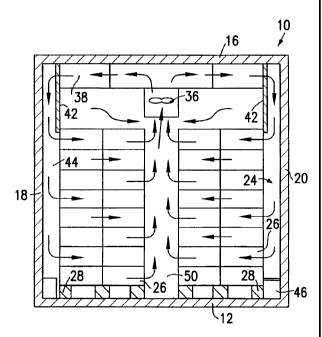
A ripening room 10 in accordance with the present
invention (as shown in Figures 1, 2, 3A and 3B) includes
a floor 12, a rear wall 14, a ceiling 16, two sidewalls
18, 20 and a front wall 22. The front wall 22 is
provided with a pair of doors (not shown) that can be
opened to enable access to produce in the room 10. The
floor, walls, doors and ceiling 12, 14, 16, 18, 20 and 22
are insulated and form a generally gas-tight chamber for
treating produce to control its ripening as will be
discussed below.
The ripening room 10 may optionally be mounted on wheels
(not shown) and used as a transportable unit.
Alternatively, it may be designed for use as a stationary
unit.
Produce is moved into and out of the ripening room
chamber through the doors at the front wall 22 in
separate palletized loads 24. Each palletized load 24
comprises a plurality of protective boxes 26 to unitize
and protect the produce. The protective boxes 26 are
block-stacked on pallets 28 for easy handling during
their loading into and removal from the ripening room 10.
Each pallet 28 may be 40 inches by 48 inches with 48
CA 02253726 1998-10-23
WO 97/39639 PCT/i7S97/06572
9
protective boxes tightly block-stacked thereon. Each of
the protective boxes 26 includes side openings 30, which
correspond with similar openings in adjacent boxes 26 to
facilitate airflow through the boxes 26.
S
Ripening rooms in accordance with the invention can be
constructed in a variety of sizes depending on the
maximum load capacity desired. The ripening room 10
shown in the drawings is sited to house (when fully
loaded) two rows of palletized produce, each containing
10 palletized loads. The ripening room chamber has a
height of 2.85 m, a width of 2.82 m, and a length of
13 m. As will be discussed further below, the ripening
room 10 need not be fully loaded to be operational; it
25 can be conveniently operated under a variety of partial
loading conditions.
The ripening room 10 is equipped with five air control
units 32 mounted on the ceiling centrally between the
sidewalls 18, 20. The air control units 32 each include
an air heater and air cooler 34 for controlling air
temperature and two tube axial fans 36 for controlling
airflow. For ripening rooms designed as transportable
units, hydraulic motors are preferably used (instead of
2S electric motors) to drive the fans. Hydraulic motors
emit less heat and require less space than electric
motors.
CA 02253726 1998-10-23
WO 97/39639 PCT/US97/06572
Each fan 36 of an air control unit 32 is positioned to
provide air circulation to two palletized loads 24. The
air control units 32 are each connected to two ducts 38,
each of which extends toward an opposite sidewalls 18,
5 20.
The ceiling 16 is also equipped with lights 40 between
adjacent air control units 32 to provide lighting in the
ripening room chamber when needed.
Two stationary side baffles 42 extend along the length of
the upper portion of the chamber, each parallel to and
proximate one of the sidewalls 18, 20. The side baffles
42 extend downwardly from the ceiling 16 and have a
height of about 87.5 cm. They are spaced apart from
respective proximate sidewalls 18, 20 by a distance of
about 20 cm. This gap forms a portion of a side airspace
44 that, as will be described further below, forms a high
or low pressure plenum to facilitate air circulation in
the chamber.
The ducts 38 leading from the air control units 32 are
each connected to openings in one of the baffles 42 to
enable air flow between the side airsDaces 44 and the air
control units 32.
The side airspaces 44 are further enclosed by the outer
sides of the two rows of palletized loads 24 placed in
CA 02253726 1998-10-23
WO 97139639 PCT/US97J06572
11
the ripening room 10. As shown in Figures 3A and 3B, the
palletized loads 24 are arranged in the chamber to abut
the lower edge of each side baffle 42. The palletized
loads 24 also abut metal curbs 46 on the floor-sidewall
corners of the ripening room 10. (Metal curbs are
preferably used in transportable ripening room units,
while concrete curbs are preferred in stationary ripening
room units.) The rear sides of the rearmost palletized
loads 24 in the chamber abut the rear wall 14 of the
ripening room 10.
Two movable partitions 48 (described in further detail
below with respect to Figures 4-10) are also provided to
enclose the front end of the side airspaces 44. Thus,
the side airspaces 44 are defined by the baffles 42, the
outer sides of the palletized produce, the floor curbs
46, the room sidewalls 18, 20, the room rear wall 14, and
the movable partitions 48.
As shown in Figures 3A and 3B, the two rows of palletized
produce in the ripening room 10 are spaced apart from
each other. The space between and directly above the two
rows of produce defines an interstitial airspace or
volume 50. As will be described further below, the
interstitial volume 50 forms a high or low pressure
plenum to facilitate air circulation in the chamber.
CA 02253726 1998-10-23
WO 97139639 PCT/US97106572
12
In use, the fans 36 of the air control units 32 operate
to transfer air at controlled airflow rates between the
interstitial volume 50 and the side airspaces 44. The
fans 36 can transfer air in twa directions, that is, they
can be operated to transfer air from the interstitial
volume 50 to the side airspaces 44 during one time period
as shown in Figure 3A, and the fans can be operated in a
reversed mode to transfer air from the side airspaces 44
to the interstitial volume 50 during another time period
as shown in Figure 3B. In the Figure 3A airflow
direction, the fans withdraw air from the interstitial
volume 50 thereby creating a low pressure plenum therein
and exhaust the air into the side airspaces 44, creating
a high pressure plenum therein. This pressure
differential causes air from the side airspaces 44 to
circulate through the openings 30 in the protective boxes
26, around the produce contained therein, and into the
interstitial volume 50 between the rows of palletized
produce to then again be exhausted by the fans 36.
The side baffle 42, the movable partitions 48, and the
floor curbs 46 enclosing the side airspaces 44 enable
substantially all of the forced airflow resulting from
the pressure differential to flow through the openings 30
of the protective boxes 26 and accordingly, around the
produce contained therein.
The pressure differential is thus efficiently utilized to
uniformly circulate air throughout the produce load. The
CA 02253726 1998-10-23
WO 97/39639 PCT/US97/06572
13
forced air circulation enables the temperature o~ the
produce to be controlled through control of the airflow
temperature by the air control units 32. The forced air
circulation also enables effective treatment of t!:~
produce by ethylene or other gases used to furthe_
control ripening. (An ethylene generator 52 is located
in the ripening room chamber to disperse ethylene gas
into the chamber at preselected times.)
If the cooler is activated to circulate cool air trough
the produce, the difference in temperature between the
cool air and the produce will cause air flowing through
the produce to be heated between the entry and exit
points in the produce. Thus, in the Figure 3A air'low
direction, after a period of time, produce near the side
airspaces 44 will have lower temperatures than produce
near the interstitial volume 50. To reduce these
temperature differences, in accordance with the present
invention, the direction of airflow is periodically
reversed to that shown in Figure 3B by reversing the
direction of the fan blade rotation of the tube axial
fans 36. In the Figure 3B operation, the fans 36
withdraw air from the side airspaces 44 thereby creating
low pressure plena therein and exhaust the air into the
interstitial volume 50, creating a high pressure p~enum
therein. The pressure differential causes air fro;,i the
interstitial volume SO to circulate through the
protective boxes 26, and into the side airspaces 4~ to
CA 02253726 1998-10-23
WO 97/39639 PCT/US97/06572
14
then again be exhausted by the fans 36. By periodically
reversing the direction of airflow in this manner, the
produce can be maintained at generally uniform
temperatures.
When the ripening room 10 is only partially loaded, only
the air control units 32 needed to circulate air to
produce in the room are activated. Thus, if a particular
air control unit 32 is not located above a palletized
produce load 24, it is turned off to reduce energy
consumption.
Figures 4-7 illustrate in greater detail one of the
movable partitions 48, which generally seal the front end
of the side airspaces 24. The movable partitions 48 each
comprise an elongated generally rigid panel 54. The
outer sides of the panels 54 are fitted with flexible
resilient strips or sealing flaps 56 that generally
sealingly engage the sidewalls 18, 20 and produce boxes
26 to inhibit airflow around the sides of the partitions
48. The panels 54 preferably comprise aluminum, and the
sealing flaps 56 preferably comprise neoprene gasket
material.
2S The partitions 49 each include a wheel assembly 56 (shown
in greater detail in Figures SA and 5B) rotatably
attached to the upper end of each panel 54. The wheel
assembly 56 includes four wheels 58 that are movable
CA 02253726 1998-10-23
WO 97/39639 PCT/US97/06572
along a track 60 mounted on the ceiling 16 of the
ripening room 10. (A front view of the track 60 is shown
in Figure 6). The opposite bottom end of each panel 54
includes a plug member 62 extending therefrom that is
5 slidingly mounted in a guide rail 64 located on one of
the floor curbs 46. The partitions 48 can thereby be
easily moved along the length of the ripening room 10.
The movable partitions 48 enable the front ends of the
10 side airspaces 44 to be quickly and easily enclosed when
the ripening room 10 is fully loaded or under a variety
of partial loading conditions. For example, in Figure 1,
one of the rows of palletized produce is completely
filled, while the other is only partially filled. The
15 movable partitions 48 are independently positionable at
the outer edge of the frontmost palletized produce load
24 in each row to enclose each side airspace 44.
Figures 8A, 8B and 8C illustrate an alternative partition
70. The partition 70 includes a generally rigid panel 72
and a sealing flap 74 extending around the periphery of
the panel 72. The flap 74 is movable between an extended
use position and a collapsible transportable position.
In the extended use position, the flap 74 is outwardly
extended with respect to the panel 72 to sealingly
enclose the side airspaces 44. In the collapsible
position, the flap 74 is inwardly movable with respect to
the panel 72 so that the partition 70 can be easily moved
CA 02253726 1998-10-23
WO 97/39639 PCT/US97/06572
16
to another position along the length of the ripening
room 10.
The sealing flap 74 can be moved between the collapsible
position and the extended use position by means of an
actuating mechanism that can be operated with a single
hand. The actuating mechanism comprises a handle 76
rotatably mounted at the center of the panel 72, a handle
base 78 fixedly connected to the handle 76, and four bars
80 each having one end pivotally connected to the base
78. The opposite end of each bar 80 is pivotally
connected to one end of one of four rods 82. The rods 82
each slidably extend through two guides 84 attached to
the panel 72. The opposite distal ends of the rods 82
are each attached to a portion of the flap 74 at one side
of the panel 72. In Figure 8A, the flap 74 is shown in
an extended use position. The flap 74 can be made
collapsible so that the partition 70 can be moved by
turning the handle 76 counterclockwise as shown in
Figures lOB and lOC. As the handle 76 is turned, the
rods 82 are drawn inward toward the center of the panel
72, relieving tension in the flap 74. Therefore, in a
single hand operation, the flap 74 can be moved between
collapsible and extended positions.
Figures 9 and 10 illustrate a further alternate partition
90. The partition 90 is similar to the partition 70 of
Figures 8A-C, but includes a modified actuating mechanism
CA 02253726 1998-10-23
WO 97/39639 PCT/US97/06572
17
92. The actuating mechanism 92 (shown in greater detail
in Figure 10) comprises a handle 94 rotatably mounted at
the center of the panel 72, two extensions 96 fixedly
connected to the handle 94, and four elongated rods 98
S pivotally connected to ends of the extensions 96. The
distal end of each rod 98 extends through a guide 84 at
the center of an edge of the panel 72 and is attached to
the flap 74. The opposite proximate ends of the rods 98
connected to the extensions 96 are off center with
respect to the panel 72 such that when the handle 94 is
turned in one direction (clockwise in the embodiment
illustrated), the proximate ends of the rods 98 are drawn
toward the panel center, and the sealing flap 74 is
extended outward with respect to the panel 72. When the
1S handle 94 is turned in the opposite direction, the
proximate ends of the rods 98 are moved away from the
panel center and the sealing flap 74 is pulled inward to
a collapsible position. The actuating mechanism 92 thus
conveniently enables the sealing flap 74 to be moved
between extended and collapsible positions in a single
hand operation.
During use of the ripening room 10, there will be a
gradual buildup of ethylene, carbon dioxide and other
2S gasses in the room chamber. Accordingly, the room
chamber is provided with a ventilation system to
periodically replace air in the chamber with fresh air.
In many operations, the ventilation system can be
CA 02253726 1998-10-23
WO 97/39639 PCT/US97/06572
18
operated for a half hour period twice a day to provide
adequate ventilation.
Figures 11-13 illustrate a ventilation system in
accordance with the invention particularly suitable for
transportable ripening rooms. The ventilation system
includes two conduits, each extending along the length of
the ripening room 10 through one of the hollow metal
curbs 46 located on the floor-sidewall earners of the
l0 ripening room 10. The front end of each conduit leads to
a perforated vent 68 (shown in Figure 4) which is open to
the interstitial volume S0. As shown in greater detail
in Figure 13, the opposite rear end of each conduit leads
to a port 110 in the rear wall 14 that can be opened to
air outside the ripening room. Another set of ports 112
are also provided in the rear wall 14 permitting airflow
between the side airspaces 44 and air outside the
ripening room. Each of the ports 110, 112 is equipped
with a spring loaded damper 114 (schematically shown in
Figure 13) that in normal use of the room 10 is closed,
but can be opened to enable air flow through the ports
110, 112.
When the tube axial fans 36 of the room 10 are operated
in the Figure 3A mode, a high pressure plenum will be
formed in each of the side airspaces and a low pressure
plenum will be formed in the interstitial volume.
Accordingly, as shown in Figures 11-13, when the ports
CA 02253726 1998-10-23
WO 97/39639 PCT/US97/06572
19
110, 112 are opened, ports 112 act as intake ports
enabling fresh air to be sucked therethrough into the low
pressure interstitial volume SO (indicated by airflow
direction 116), and ports 110 act as exhaust ports
S enabling air in the high pressure side airspaces a4 to be
released to the atmosphere (indicated by airflow
direction 118).
When the fans 36 in the ripening room 10 are operated in
a reversed mode (airflow in the direction shown in Figure
3B) and the ports 110, 112 are opened for ventilation,
ports 110 will act as intake ports and ports 112 will act
as exhaust ports.
Figures 14 and 15 illustrate a ripening room 120 with an
alternate ventilation system, particularly suited for use
in stationary ripening rooms. The ventilation system
includes an intake port 122 in the ceiling 16 at the
front of the ripening room 120 enabling fresh air to flow
into the chamber when the port 122 is opened. It also
includes an exhaust port 124 in the ceiling 16 at the
rear of the ripening room 120. The exhaust port 124 is
equipped with an exhaust fan 126 for drawing air out of
the chamber and releasing it into the atmosphere.
Although the ripening rooms shown in the drawings are
designed for single-tiered pallet stacking, it should be
understood that aspects of the present invention are also
CA 02253726 1998-10-23
WO 97139639 PCT/US97I06572
applicable to multi-tiered ripening rooms. In multi-
tiered ripening rooms such as those disclosed in i.u.S.
Patent Nos. 5,373,780 and 4,824,685, a frame support
structure or racking is provided to support two or more
5 tiers of stacked palletized produce loads so that the
quantity of produce that can be treated for a given
amount of floor space is increased. The frame support
structure enables the palletized produce to be arranged
in two spaced apart rows, each of which is vertically
10 stacked with one or more additional tiers of palletized
produce. The tiers of palletized produce are vertically
spaced-apart to facilitate loading and unloading of each
tier. Intermediate baffles similar to the baffles 42
extend from the frame structure to seal the vertical
15 spacing between the tiers so as to inhibit direct airflow
between the side airspaces and the interstitial airspace
through the vertical spacing.
Although the present invention has been described in
20 terms of specific embodiments, various changes and
modifications may be suggested to one skilled in the art.
The invention is intended to encompass such changes and
modifications as fall within the scope of the appended
claims.