Note: Descriptions are shown in the official language in which they were submitted.
CA 02253786 1998-11-04
WO 97/42530 PCT/US97/06035
REFRACTIVE INDEX GRADIENT LENS
Field of Invention
The present invention relates to optical products such as optical lenses and
semi-finished lens blanks having a continuous progression of power from the
distance focus to the near focus, and more particularly to refractive gradient
progressive multifocal lenses having a reduced amount of unwanted peripheral
astigmatism, and refractive gradient bifocal lenses without a wide blurred
blended
area defining the add zone.
Background of the Invention
Commercial multifocal lenses come in a variety of materials and are
generally made of plastic or glass. These lenses come in many styles, sizes,
and
can be of a lined, blended or progressive design. Of these designs, lined
bifocals
have long been used by those requiring near vision correction. The lined
bifocal
segment is fused in the case of glass, or molded in the case of plastic. In
either
case, the bifocal segment line is noticeable and represents the junction of
near and
distance optical portions in the lens or a semi finished blank providing the
distance focus and near focus. Bugbee (U.S. Patent No. 1,509,636),Meyrowitz
(U.S. Patent No. 1.445.227),and Culver (U.S. Patent No. 2,053.551) teach fused
lined bifocals or multifocals. While lined bifocals have been used
successfully for
many years, they nave several drawbacks. First, they are extremely noticeable
and
thus are not cosmetically appealing: second, the segment line creates a blur
when
looking from far to near objects and vice versa; and third, there is an abrupt
change of focal length when looking from far to near objects and back again.
No
optical area is provided with intermediate power (focal length) at all, unless
a
lined trifocal is used.
1
CA 02253786 1998-11-04
WO 97142530 PCT/US97/06035
Blended bifocals, such as those disclosed in W082/03129, are bifocals which
retain a clear demarcation between the optical zones v.~ith far focus and near
focus; however, the line of demarcation is blended to make it far less
noticeable.
Blended bifocals attempt to solve the cosmetic disadvantage of a lined
bifocal, but
in doing so create a wide blended blur zone when looking from far to near
objects
and back again, as well as failing to provide intermediate vision.
Progressive addition lenses are a type of multifocal lens which incorporate
a progression of power changes from far to near correction, creating a
progressive
vision transition from far to near power and back again. Progressive addition
lenses represent an attempt to solve the problems discussed above. Although
progressives solve several deficiencies of lined or blended bifocal lenses,
they
require other compromises in optical design, which in turn compromise the
visual
function of the lens optic, as discussed below. Progressive addition lenses
are
invisible, and provide a natural transition of power from far to near foci.
Methods of making progressive addition lenses are disclosed, for example,
by Harsigny (U. S. Patent No. 5,488,442), Maitenaz (U. S. Patent No.
4,253.747),
Maitenaz (U. S. Patent No. 3,687,528), Cretin et al. (U. S. Patent No.
3,785,725),
Maitenaz (U. S. Patent No. 3,910,691), Winthrop (U. S. Patent No. 4,055,379),
Winthrop (U. S.,Patent No. 4.056.311), and Winthrop (U. S. Patent No.
4,062,629). These lenses, however have certain deficiencies which are inherent
in
their design. A first deficiency is that only a relatively narrow reading
channel
width of about 3-8 mm, defined as the space between two meridional imaginary
lines characterized by astigmatism of +/-0.50 diopters or more. This reading
channel represents the progressive transition of focal lengths from far to
near,
enabling one to see from far to near in a somewhat natural manner without
experiencing the abrupt change of power of a lined bifocal. A second
deficiency is
that progressive addition lenses can only provide a relatively narrow reading
zone
which is about 22 mm wide or less. A third major deficiency is the unwanted
peripheral astigmatism which is created due to the nature of the progressive
optical design. This unwanted peripheral astigmatism creates significant
visual
2
CA 02253786 1998-11-04
WO 97/42530 PCT/US97/06035
distortions for the user. Manufacturers are interested in limiting the amount
of
unwanted astigmatism in order to enhance the visual performance, and thus
increase the acceptance levels of their different designs. In practice, all
progressive lens designs represent compromises among having a lens with the
widest possible channel, the lowest amount of unwanted astigmatism and the
widest add power zone. A fourth major deficiency is the difficulty of properly
fi~.tin<.: the patient with a progressive; ard, the fifth deficiency is the
low tolerance
for fitting error allowed by these designs.
Numerous attempts have been made to solve the inherent problems
discussed above wah lined, blended, trifocals, and progressive multifocals.
H~wever, no other commercially viable options have been found. The ophthalmic
lens design disclosed in Frieder (U.S. Patent No. 4,952,048) and Frieder (U.S.
Patent No. 4,869.588) addresses some of these deficiencies, but fails to
provide a
satisfactory solution due to both manufacturing difficulties and poor cosmetic
appearance at moderate to higher add powers. Although these patents disclose a
lens with several improved features, in the moderate to higher add powers from
+ I .75 to +3.00 diopters, this lens caused the front (convex) surface
defining the
periphery of the near power zone to bulge anteriorly and thus cause a visible
optical distortion on either side of the reading zone. This feature
significantly
reduced its commercial appeal. Furthermore, difficulties in manufacturing this
lens made the lens less commercially viable.
Maeda (U.S. Patent No. 4,944,584)discloses a refractive Gradient lens using
a first partially cured substrate layer. A second uncured resin layer is added
and
diffusion occurs between these two layers during curing to create a third
diffusion
layer having a refractive index gradient which varies continuously between the
refractive indices of the first and second layers. To achieve this diffusion
layer,
the assembly containing the second layer is heated at specified temperatures
for
20-26 hours. The time required for curing to form the diffusion layer makes
this
procedure unattractive from a commercial standpoint. Furthermore, it is known
that the process disclosed in Maeda, which includes demolding a partially
cured
3
CA 02253786 1998-11-04
WO 97/42530 PCT/US97106035
lens or semi-finished blank, can create yield problems. Thus, while it may be
theoretically possible to achieve Maeda 's third, continuously varying,
refractive
index gradient diffusion layer, actual manufacturing difficulties may reduce
the
likelihood that the Maeda lens could achieve commercial success.
In addition to the deficiencies previously mentioned concerning bifocal and
multifocal lenses, these lens styles are ~Iso thicker than single vision
lenses of
equivalent distance power, since they are required to provide for additional
plus
power in the add power zone. This added thickness on the anterior surface of
the
lens tends to detract from their cosmetic appeal and adds additional weight to
the
lens. Several solutions to this problem have been proposed.
Blum (U.S. Patent No. 4,873.029) describes the use of a preformed wafer
having desired multifocal segments formed thereon and adding a resin layer of
a
different index of refraction onto the surface of the preformed wafer. In this
approach, the preformed wafer is consumed during the molding process so that
the preformed wafer ultimately forms part of the lens. While this approach
produces a cosmetically improved lens, the process requires hundreds of
gaskets
and back convex spherical and toric molds. These molds ultimately make the
concave side of the finished lens. Furthermore, with this approach the bifocal
or
multifocal zone is not invisible due to the significant refractive mismatch
needed
and the lack of a transition of refractive indices of various materials.
Various patents disclose refractive gradient bifocal, multifocal or
progressive lens styles, e.g.,Dasher (U.S. Patent No. 5,223,862), Maeda (U.S.
Patent No. 4,944,584), Yean (U.S. Patent No. 5,258,144), Naujokas (U.S. Patent
No. 3,485,556), Okano (U.S. Patent No. 5,305,028), Young (U.S. Patent No.
3,878,866),Hensler (U.S. Patent No. 3,542,535), and Blum (U.S. Patent No.
4,919,850). However, the commercial production of refractive gradient
multifocal
ophthalmic lenses to date has not been commercially successful due to
chemistry,
technology, manufacturing and cost limitations.
4
CA 02253786 2005-06-06
In PCT Patent Application No. WO 93/19366, Soane discloses producing a
multifocal lens having a bifocal and astigmatic area on the back, concave side
of
the front optical wafer preform. Soane discloses curing a resin material
having a
different index of refraction from the optical wafer preform onto the back of
the
front optical wafer preform using an appropriate back convex mold having the
correct curvature. This approach, however, requires that a significant number
of
front optical preforms be inventoried.
In view of the above, it is desirable to have a progressive multifocal lens
which would allow the end user a wide and natural progression of vision when
looking from far to near, being substantially free of or having a reduced
amount of
unwanted peripheral astigmatism, having a wide reading zone, requiring a
smaller
inventory of skus (stock keeping units) and being relatively forgiving and
easy to
fit for the patient. In addition, it would be desirable to have a progressive
multifocal lens which has substantially the same thickness as a single vision
lens
of equivalent distance prescription, and which cosmetically is almost
invisible in
appearance. Also, it is desirable to manufacture such optical products in a
way
that reduces the amount of processing time.
Summary Of Invention
The present invention solves these and other inconveniences of the prior
art by providing an optical product such as a composite refractive gradient
progressive multifocal preform, lens or semi-finished lens blank and method of
manufacture which provides for simply, quickly and inexpensively manufacturing
a composite refractive gradient progressive multifocal optical preform, lens,
or
semi-finished lens blank. The optical product, such as a lens, comprises a
composite of at least three different layers, including a base layer having a
region
of varying thickness which can be either depressed or raised, a transition
zone and
an outer layer. Each of the layers of the composite are separately applied and
are
bonded to an adjacent layer or layers. In addition, each layer has a different
and
CA 02253786 2005-06-06
distinct refractive index which allows for a progressive multifocal lens
having a
wide and natural progression of vision when looking from far to near.
Interposed
between a base layer and an outer layer is a transition zone comprised of at
least
one transition layer. The transition zone has an effective refractive index
which is
intermediate between the refractive indices of the base and outer layers.
Preferably, the effective refractive index is approximately the geometric mean
of
the refractive indices of the base and outer layers. In addition, the lens of
the
present invention is substantially free of or has a reduced amount of unwanted
peripheral astigmatism, incorporates a wide reading zone and is relatively
forgiving and easy to fit for the patient, and possesses a cosmetic appearance
which is substantially invisible.
More particularly, the present invention provides an optical product,
comprising: a base layer having a first refractive index and a region of
varying
thickness; an outer layer having a second refractive index different from the
first
refractive index; and a transition zone comprising at least one layer bonded
between the base and outer layer, each of the layers having a different
refractive
index and which differs from the refractive indices of the base layer and the
outer
layer wherein the refractive index of each of said at least one layer is
substantially
constant throughout the layer and the transition zone has an effective
refractive
index which is approximately the geometric mean of the refractive indices of
the
base and outer layer.
In addition, the present invention drastically reduces the number of front
optical preforms that must be inventoried. For example, assuming add powers of
+1.00 to +3.00 diopters, sphere powers of +4.0 to -4.0 diopters, cylinder
powers of
plano to -2.0 diopters, 3 base curves of the lenses, right and left eyes; and
assuming the astigmatic power is added as is disclosed by Soane (WO 93/19366)
on the concave side of the front optical preform, then for each type of
material it
would be necessary to inventory the following skus:
6
CA 02253786 2005-06-06
1. for bifocal lenses - 9,720 different front optical preforms for astigmatic
bifocal correction are required, based on 180 different astigmatic degrees x 3
base
curves x 2 eye decentrations x 9 bifocal add powers x 1 material; and
2. for single vision lenses - 540 different front optical preforms for
astigmatic correction only are required, based on 180 different astigmatic
degrees
x 3 base curves x 1 material.
Thus, in the above example Soane would require a total of 10,260 front
optical preforms, in addition to back-up inventories that may be required for
each
sku. In contrast, the present invention requires only 540 skus and only 3
pairs of
molds based on 180 different astigmatic degrees x 3 base curves x 1 material.
Furthermore, Soane would require numerous gaskets and molds to be used and
would not produce a bifocal or multifocal zone as cosmetically invisible as
the
present invention because of the significant refractive
6a
CA 02253786 1998-11-04
WO 97/42530 PCT/US97/06035
index mismatch needed and the lack of a transition layer or layers of
different
refractive index.
Brief Description of the Drawings
FIG. 1 is a cross section view of an optical preform according to the
present invention.
FIG. 2 is a cross section view of an optical preform having a transition
layer.
FIG. 3 is a cross section view of an ontical preform positioned against a
mold.
FIG. 4 is a cross section view of a mold positioned against an outer layer.
FIG. 5 is a cross section view of an optical product according to the present
mvent~on.
FIG. 6 is a cross section view of an alternate embodiment of the present
invention.
Detailed Description
FIG. 1 illustrates a base layer which is an optical preform 10 containing
both spherical and astigmatic prescriptions being made of a material having a
refractive index of 1.49 and having a spherical convex surface with a modified
region 20 which has been modified by mechanical means to form a surface
depression which approximately defines the boundaries of the progressive
multifocal zone. The modified region 20 could be made on either the convex or
concave surface. However, in this embodiment the modification is performed on
the convex surface. The astigmatic curves or toric surface 30 is located on
the
concave side. For this reason the appropriate toric optical preform is
selected and
rotated to the appropriate astigmatic axis for the particular prescription
needed
7
CA 02253786 1998-11-04
WO 97/42530 PCT/LTS97/06035
and the optical modification is performed on the front convex surface in the
correct orientation relative to the desired astigmatic axis. Not only does the
modified region 20 take into account the astigmatic axis needed but also at
the
appropriate and different decentration location for each of the right and left
eyes.
Although, for purposes of illustration, mechanical modification of the
surface is disclosed, it should be under rood that any method which would
create
the needed alteration to the surface geometry would work. For example, by way
of illustration only, the surface depression can be accomplished by a variety
of
methods which include stamping, burning, sculpturing, grinding, ablating, and
casting. The method of obtaining the surface depression is somewhat dependent
on the cure condition of the preform, as well as the composition of the
preform
material. For example, in order to grind the preform, the preform should
generally be in a fully cured or hardened condition.
The modified region 20 is formed on the optical preform 10 to create a
surface depression which will generally define the boundaries of the
progressive
multifocal zone. The desired geometry of the depression can be calculated
using
known optical formulas pertaining to refractive index. In general, nd = n~d~ +
n.,d~, where n is the overall refractive index of the optic, d is the
thickness of the
optic, n1 is the refractive index of the optical preform, d, is the thickness
of the
optical preform, n, is the refractive index of the added layer and d~ is the
thickness of the added layer. The power at any point is determined by the
overall
or effective refractive index at that point, which in turn is controlled by
the depth
of the cavity or depression at that point from the surface contour (sag
depth). and
the refractive index of the cured resin filling the cavity.
Depending upon the modification method used as well as the material of
the optical preform, once the modification is performed and the desired
surface
topography is achieved, the newly altered surface may be further modified by
polishing, surface casting, or other methods known in the art to smooth over a
roughened surface. In a preferred embodiment, the mechanically altered surface
8
CA 02253786 1998-11-04
WO 97/42530 PCT/ITS97/06035
is mechanically abraded to achieve a rough surface. As shown in FIGs. 2 and 4,
a
thin layer of resin is then applied to the entire convex surface of the
optical
preform 10 including the modified region 20 to form a transition layer 40
which
comprises a transition zone 45. In an alternate embodiment, the transition
layer
can be applied to only a portion of the preform 10 which includes at least the
modified region 20.
Suitable materials for the optical preform may generally include copolymers
of allylics, acrylates, methacrylates, stryenics and viylics, such that the
glass
transition temperature is between approximately 50°C and 200°C
and the
refractive index is between approximately 1.4.4 and 1.56. For example, such
materials may include poly(diethyl bis allvl carbonate), poly-(bisphenol A
carbonate) and poly(styrene)-co-(bisphenol .A carbonate diacrylate)-co-
(bisphenol
A carbonate dimethacrylate).
Materials for the transition zone may generally include copolymers of
allylics, acrylates, methacrylates, stryenics and viylics, such that the glass
transition
temperature is between approximately 50°C and 100°C and the
refractive index is
between approximately 1.52 and 1.65. For example, such materials may include
poly(poly oxy methylene diacrylate)-co-(ethoxvlated bis phenol A carbonate
diacrylate>-co-(furfuryl actvlate).
The refractive index of the transition layer 40 is purposely formulated to be
mismatched to the refractive indices of the preform 10 and a subsequently
applied
outer layer 50, in order to achieve a transition midpoint of the refractive
gradient
being achieved. This technique is used in order to render the progressive
multifocal area as invisible as possible. In addition, when the transition
layer 40
is applied to the preform 10, it can prepare the surface of the preform 10 for
good
bonding with the next resin layer to be applied and can significantly smooth
out
surface irregularities which might remain and be visible once another resin
layer is
applied.
9
CA 02253786 1998-11-04
WO 97/42530 PCT/US97/06035
Although the refractive index of the transition layer 40 is formulated to
achieve minimum internal reflection from the interface, other embodiments
using
different surface modification techniques, or optical prefotms made of
different
materials may be used, or the refractive in~'ex of the coating may be
formulated to
be closer to that of the optical preform or to that of the next resin layer to
be
applied, or may not even be needed. As shown in FIG. 6, an alternative
embodiment of the present invention rray have at least one additional
transition
layer 40, with the transition layers being placed on top of each other after
partially
or fully curing each layer. Each transition layer 40 has a different
refractive index
such that the layers collectively form a transition zone 45 which has an
effective
refractive index that is approximately the geometric mean of the optical
preform
1U and the outer layer 50. Having a transition zone with an effective
retractive
index approximating the geometric mean makes the transition of refractive
indices
less abrupt and thus make the finished multifocal zone more invisible.
Although
the effective refractive index should approximate the geometric mean, a
variation
of +/-.03 units produces acceptable results.
Suitable materials for the outer layer 50 may generally include copolymers
of allylics, acrylates, methacrylates, stryenics and viylics, such that the
Mass
transition temperature is between approximately 60°C and 225°C
and the
refractive index is between approximately 1.56 and 1.70. 1"or example, such
materials may include ethoxylated bisphenol A diacrylate, ethoxylated
bisphenol A
dimethacrylate, ethoxylated 1,4-dibromo-bisphenol A diacrylate, bis(4-
acryloxyethoxyphenyl)phosphine oxide, 1.4-divinyl benzene, bromostyrene, and
vinylcarbazole.
In other embodiments of the present invention, an additional resin layer or
layers may be interposed between the base layer and the transition zone. Also,
additional resin layers can be interposed between transition layers in the
transition
zone or between the transition zone and the outer layer or layers. This
additional
layer or layers should have a surface energy that sufficiently matches
adjacent
CA 02253786 1998-11-04
WO 97/42530 PCT/US97/06035
layers so that the resin can provide the desired degee of coating of the
underlying
layer.
Although in the preferred embodiment the transition layer 40 is applied by
brushing, the layer may also be applied by other techniques readily known in
the
art. For example, such techniques as spin coating, dip coating, spray coating
or
others may be used.
Once the transition layer 40 is applied to the convex surface of the optical
preform 10, the transition layer 40 is preferably partially cured. The curing
process may be performed with any known curing method including a thermal
cure. LTV cure, visible light cure, or combination thereof, in the absence or
presence of oxygen using the appropriate initiators, atmospheric environment,
and
curing source. In the preferred embodiment, the transition layer 40 is
partially
cured in an oxygen free nitrogen environment using ultraviolet light within
the
range of approximately 250-400 nm. However, use of visible light within the
range
of about 400-450 nm in an oxygen free nitrogen environment also may be used.
When a UV source is used for curing, the optical product can be rapidly
manufactured since the curing time for a transition layer can be less than
five
minutes and generally will not exceed an hour.
As shown in FIGs. 3 and 4, once the modified region 20 is formed in the
optical preform 10 to achieve the desired surface topography and the desired
transition zone 45 is applied, the optical preform with the transition zone 45
is
ready to be provided with an outer layer 50 which is preferably formed by
casting
a resin onto the transition zone 45. The outer layer 5U is formulated to have
a
refractive index significantly different from the optical preform 10 material.
In the
preferred embodiment, the resin of the outer convex layer 50 is formulated to
have a refractive index of about 1.66; the optical preform 10 material has a
refractive index of about 1.49; and the refractive index of the transition
layer 40 is
a constant of about 1.57. Thus, the 1.66 refractive index convex outer layer
50 is
cast from a resin onto the 1.574 refractive index conveh transition layer 40
which
11
CA 02253786 2005-06-06
is affixed to the 1.49 refractive index optical preform 10. This is preferably
done
in this example using a single vision spherical mold 60 which is selected to
cast the
desired outer convex curvature onto the optical prefotm IO having the
transition
layer 40. If the convex curvature of the optical preform 10 is aspheric in
design,
the appropriate single vision mold selected for SurfaceCasting the outer
convex
surface will be an aspheric design rather than spherical design. This outer
curvature will control the desired distal ;cg power achieved. Appropriate
techniques for providing the cast layer are described in Blum (U.S. Patent No.
5,178,800) ( "'800'7. Blum (U.S. Patent No. 5.147,585) ( "585'x. Blum (U.S.
10 Patent No. 5,219,497) ( "~97'~, and Blum IU.S. Patent No. 4,873,029)
('029'x,
however, using a single vision mold.
These techniques are also commerci~!lv
available from Innotech, lnc. by way of its Excalibur~ SurfaceCasting~ system.
The mold 60 used to cast the outer layer 50 can be made out of any
applicable material allowing for proper cure. By way of example only.
electroformed nickel, glass. and plastic disposable molds can be used. Prior
to the
curing process, the resin used to cast the outer layer 50 can be dispensed
into the
mold 60, dispensed into a cavity 70 between the mold 60 and the prefotm 10, or
provided in the form of a partially cured polymeric layer included with the
mold
60 or attached to the optical preform 10. In embodiments where the outer layer
50 is produced from a partially cured polymeric layer which is later cured,
the
transition layer 40 or layers which produce the refractive index transition
zone 45
can be attached to the partially cured polymeric outer layer 30. In this case.
the
partially cured polymeric layer and attached refractive index transition layer
40 are
25 then cured and formed onto the optical prefortn 10. Although the preferred
embodiment does not use a gasket while casting the outer convex curvature onto
the optical preform, in certain embodiments a gasket may be used.
When the transition zone includes a plurality of layers. the refractive sndex
of each layer is selected so that the transttion zone has an effective
refractive
index that is approximately the geometric mean of the preform and the outer
12
CA 02253786 1998-11-04
WO 97/42530 PCT/US97/06035
layer. By way of example only, if the preform has a refractive index of about
1.50
and the outer layer has a refractive index of about 1.70, the refractive
indices of
three transition layers in a transition zone may be about 1.54, 1.60 and 1.66
as the
layers progress from the preform to the outer layer.
The transition zone 45 is comprised of a distinct and separately applied
layer or layers, wherein each layer has a different refractive index and is
formulated so that the transition zone 45 has an effective refractive index
which is
intermediate and approximates the geometric mean of the refractive indices of
the
optical preform 10 and the outer layer 50. The refractive index of each
transition
layer in the transition zone is generally constant throughout the entire
layer.
During the cure step, the partially cured transition layer 40 as well as the
SurfaceCast resin outer layer 50 become cured to the desired degree to form a
refractive index gradient progressive multifocal optical lens, or semi-
finished
blank. In the case of the preferred embodiments, the refractive index gradient
varies from about 1.40 to 1.06, with different thicknesses of each material
being
defined by the geometries of the convex surface topography of the modified
optical preform, the concave spherical and astigmatic surface topography of
the
optical preform and the single vision spherical concave mold surface which
adds
the desired outer convex curve onto the convex side of the modified and
customized optical preform to achieve the desired power. Innotech 's
SurfaceCasting commercial product typically applies a surface layer in a
manner
so that the distant power of the desired prescription is not substantially
changed.
However, in the present invention the outer layer may or may not be confined
to
leaving the distant power substantially unchanged. Furthermore, unlike
Innotech 's
commercial SurfaceCasting technology and the technology of the '800, 585,
029 and x.97 patents, the progressive addition multifocal region of the
present
invention is not added by way of a multifocal mold but rather is created due
to
the altered surface topography of the optical preform 10 as well as the
refractive
index gradient which results from casting a spherical or aspheric surface onto
an
13
CA 02253786 1998-11-04
WO 97/42530 PCT/US97/06035
altered surface topography which is specifically altered to cause different
varying
thickness of a refractive gradient.
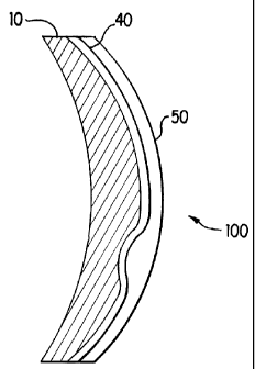
Referring to FIG. 5, once the casting process is completed, the composite
refractive gradient progressive multifocal lens 100 is removed from the mold
60.
The newly formed composite Iens 100 can be post cured in the mold or outside
of
the mold by techniques which are well known in the art.
The method of the present invention can be used to make optical preforms,
optical lenses, and optical semi-finished blanla. Resins used to form any and
all
layers can be photochromatic if desired, so Tong as the proper refractive
index is
achieved for the particular layer. In addition, although the preferred
embodiment
has been illustrated by using resins to form the layers, it is understood that
the
layers of the composite can also be made f. om a glass or a combination of
resin
and Mass .
The outer layer of the newly formed composite lens 100 can be surface
treated in any manner used in the optical industry, including applications of
anti-
reflective coatings, scratch resistant coatings, tints, photochromatic
coatings and or
photochromatic impregnation techniques, soil resistant coatings, etc.
Furthermore,
in-mold transfer of various coatings can also be utilized a~ pan of the
fabrication
process as opposed to being applied after the lens or semi-finished blank is
fabricated.
The present invention provides bifocal add powers and the desired
decentration for the right and left eyes, and establishes the correct optical
toric
axis. These results are preferably accomplished by modification of the convex
surface of the optical preform. In other embodiments of the invention, the
modification to the geometry of the optical preforms can be made by modifying
the concave side of the optical preform in the same or similar manner as the
modification is done to the convex surface. In this case, the optical prefotm
14
CA 02253786 1998-11-04
WO 97/42530 PCT/US97/06035
surface modification and casting are performed on the concave side of the
optical
preform as opposed to the front side of the optical preform.
Also, in certain other embodiments, the surface topography modification of
the optical preform can be made with a certain depth and geometry and aligned
opposite a bifocal or multifocal zone of a mold containing the appropriate
surface
curvature needed. This is done to add not only the appropriate outer
curvature,
but also to add additional confining geometry in the region of the bifocal or
multifocal zone of the finished lens. By using this approach. it is possible
to use
materials having a smaller index of refraction differential than the materials
used
in the preferred embodiment.