Language selection

Search

Patent 2253978 Summary

Third-party information liability

Some of the information on this Web page has been provided by external sources. The Government of Canada is not responsible for the accuracy, reliability or currency of the information supplied by external sources. Users wishing to rely upon this information should consult directly with the source of the information. Content provided by external sources is not subject to official languages, privacy and accessibility requirements.

Claims and Abstract availability

Any discrepancies in the text and image of the Claims and Abstract are due to differing posting times. Text of the Claims and Abstract are posted:

  • At the time the application is open to public inspection;
  • At the time of issue of the patent (grant).
(12) Patent Application: (11) CA 2253978
(54) English Title: SPACE SAVER PORTABLE CONVENTIONAL HOME COMPUTER CARRIAGE
(54) French Title: CHARIOT D'ORDINATEUR DOMESTIQUE, CLASSIQUE, PORTATIF, DE FAIBLE ENCOMBREMENT
Status: Dead
Bibliographic Data
(51) International Patent Classification (IPC):
  • A47B 21/00 (2006.01)
  • F16M 11/04 (2006.01)
  • F16M 11/28 (2006.01)
  • F16M 11/42 (2006.01)
  • G06F 1/16 (2006.01)
(72) Inventors :
  • BOURDON, PASCAL MARCEL (Canada)
(73) Owners :
  • BOURDON, PASCAL MARCEL (Canada)
(71) Applicants :
  • BOURDON, PASCAL MARCEL (Canada)
(74) Agent:
(74) Associate agent:
(45) Issued:
(22) Filed Date: 1998-11-25
(41) Open to Public Inspection: 2000-05-25
Availability of licence: N/A
(25) Language of filing: English

Patent Cooperation Treaty (PCT): No

(30) Application Priority Data: None

Abstracts

English Abstract


This present invention is a space saver, portable, home computer carriage. The
upper embodiments consists of a floating metal platform to support a computer
monitor, a
keyboard rack and a rolling shelf under the keyboard rack for the mouse.
The computer platform is able to rotate 360°, also a rotating
mechanical arm
supports the platform and enables the monitor, keyboard and mouse shelf to be
transferred from side to side and front to back. The rotating mechanical arm
is secured
with a clamp system to a table.
On the opposite side of the table, a metal frame is secured. It is designed to
support a shelf to sit the computer tower off the ground. All these
embodiments are
secured counterbalanced onto a live leg rolling system which can be related to
the under
carriage of an office chair, consisting of a vertical locking cylinder device
which adjusts
manually to different heights and also rotate the whole system 360°.


Claims

Note: Claims are shown in the official language in which they were submitted.


THE EMBODIMENTS OF THE INVENTION IN WHICH AN EXCLUSIVE
PROPERTY OR PRIVILEGE IS CLAIMED ARE DEFINED AS FOLLOWS:

1- A space saver portable, conventional home computer carriage

2- Under carriage members including ground engaging means

3- Table on under carriage is able to rotate 360° and be adjusted to
different heights.

4- A platform adapted to a conventional mechanical arm is ready to receive any
size of
computer monitor, a keyboard rack and mouse platform.

5- The mechanical arm is able to be moved from side to side and back to back
and be
set back to a storing position.

6- On the opposite side of the mechanical arm a bracket is secured to the
table allowing
suspended shelf to set a computer tower.

7- This invention makes an entertainment system become very transportable
around a
room area and very compact.


Description

Note: Descriptions are shown in the official language in which they were submitted.


CA 02253978 1998-11-25
SPACE SAVER PORTABLE CONVENTIONAL
HOME COMPUTER CARRIAGE
This invention relates to a manual rolling carriage for a conventional home
computer system designed to draw a minimum amount of space.
The present invention provides a complete conventional computer system to be
set on the rolling carriage having a conventional mechanical arm supporting
the monitor.
This floating rotating platform, keyboard rack and roll out mouse shelf,
enables platform
to be moved manually from side to side and front to back.
A mounted bracket is secured to table on the opposite side of the mechanical
arm,
this bracket permits a shelf to be set off the ground used to support a
conventional
computer tower which counterbalances the carriage.


CA 02253978 1998-11-25
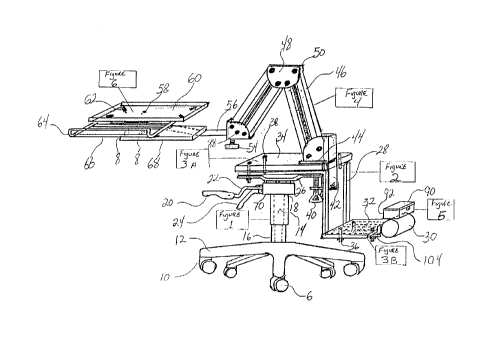
In the drawings, which illustrate embodiments of the invention:
Figure 1: is a perspective view of a space saver computer carriage in
accordance
with this invention.
Figure 2A: is a front elevation view of the under carriage showing the locking
up
and down cylinder action.
Figure 2B: is a side elevation view of the top rotating and pivoting table
mount.
Figure 3A: is a side perspective view of the shelf bracket used to support
computer tower.
Figure 3B: is a top perspective view of the shelf bracket and a counter mass
is
welded to the far end.
Figure 4A: is a front view of the plastic container enables an electrical
power bar
to be stored.
Figures 4B: is a side view of the plastic container showing an opening that
enables
power cords to freely enter and exit the container.
Figure SA: is a top view of the table to be mounted to the carriage.
Figure SB: is a top view of the shelf to be mounted on the bracket used to sit
computer tower.
Figure 6A: is a side perspective view of the mechanical arm with its side to
side
motion view.
Figure 6B: is a back perspective view of the mechanical arm showing the clamp
system.
Figure 7A: is a front elevation view of the floating rotating platform to
support the
monitor, keyboard rack and rolling shelf for mouse.
Figure 7B: is a side elevation view of figure 7A.
Figure 7C: is a top view of the monitor platform, keyboard rack and rolling
mouse
shelf. On platform a view of the adjustable mounting brackets enables monitor
base to be
secured.
2


CA 02253978 1998-11-25
In the drawings, which illustrate an embodiments of the invention the
rotating,
retractable monitor on a rolling carriage is shown generally in Figure 1,
comprises a
carriage 12. The carriage 12 is constructed of metal or plastic to reduce
weight which is
referred as the under carriage of an office chair. Transportability of the
under carriage
consists of plastic wheels 6 adapted to a rotating castors 10A. The castors 10
are
preferably provided with brakes (not shown) so when in use the under carnage
12 will
remain stationary. A locking cylinder elevation device 14 is mounted
vertically to the
under carriage 12. 14 is esthetically covered with a conventional plastic
tubing 16. The
mechanical device 22 is used to unlock the cylinder 14 to enable the height
adjustment of
the mounting bracket 26. Locking device 24 levels the mounting bracket 26
pivoting on a
hinge system 72. 70 esthetically covers mechanical locking devices which 22
and 24 is
adapted to. 18 is the pivoting point were mechanical cover 70 inter joins to
cylinder 14
permitting a 360° rotation of the mounting bracket 26.
A heavy gauge steel bracket 80 is mounted and fastened 38 to the mounting
bracket 26 with conventional nuts and bolts fasteners. Two 90° bends 84
enables the
shelf bracket 104 to sit lower. A steel mass 30 is welded to the shelf bracket
104 to
provide stability to the carriage. A cross member 86 is provided to reinforce
the bracket
80 parallel.
A set of mounting brackets 76 is welded to fastened a plastic container 92. It
consists of a plastic cover 90 and locking device 94. The container 92 is
designed to store
an electrical power bar.
3


CA 02253978 1998-11-25
On the right side of the container 92, illustrated in Figure 4B an opening is
shown
96 it is designed for the power cords to exit the container 92.
On bracket 104 a shelf made out of any type of wood or melamine 32 is fastened
into 88 to the bracket 104 with conventional nuts and bolts. This shelf 32 is
set to sit a
conventional computer tower not shown.
On bracket 80 a table 34 constructed of any type of wood or melamine is
fastened
into 82 interconnecting through the bracket 80 and secured to the table
mounting bracket
26 with the conventional nuts and bolts.
The conventional mechanical arm Figure 6 is constructed of any type of metals.
The four arms 46 are constructed out of square tubing which are connected
inside a metal
U channel 48 which allows the mechanical arm Figure 6 to have a backhoe
effect. By
extending the mechanical arm the hand which is referred as 56 remains up at
the same
level. The hand 56 leveling adjustment 54 is adapted to receive manual
cranking
adj ustment.
The mechanical arm Figure 6 is fastened onto a teflon plate 44 and a metal
clamp
42 which allows the mechanical arm Figure 6 to have a rotation device 44. The
clamp 42
is fastened to the table 34 with a conventional tightening device 40.
The hand 56 illustrated in Figure 7 supports the metal platform 60 which is
used
to sit a conventional computer monitor not shown. Four clamps 2 are used to
secure the
4


CA 02253978 1998-11-25
monitor base to the platform 60. Slots 4 are allowing the clamps 2 to fastened
any size
conventional monitors. The platform 60 is fastened onto a teflon plate 58
which allows
the platform 60 to rotate 360°.
Welded parallel on the underside of the platform 60 are two metal tubing 98
which allows a metal rack 64 slideably be received in 98 allowing the rack 64
to hold in a
leveled position. The rack 64 will receive and support a conventional computer
keyboard
not shown.
As shown clearly in Figure 7C a set of drawer tracks 66 are fastened parallel
to the
rack 64. Any type of wood platform 68 is assembled with a set of conventional
drawer
wheels 8 allowing it 68 to roll inside the track back and forth. This platform
68 when
extracted is used to set computer mouse not shown.


CA 02253978 1998-11-25
PRACTICALITY
This invention can be used in any room for example it can be stored on either
side
of a sofa and easily transported manually to the corner of the sofa. The
locking castor
will remain the under carnage stationery and by a simple height adjustment,
table rotation
and mechanical arm extension the monitor platform, keyboard rack and mouse
shelf
displaying it over a person's lap and at the same time having the computer
tower to the
side.

Representative Drawing
A single figure which represents the drawing illustrating the invention.
Administrative Status

For a clearer understanding of the status of the application/patent presented on this page, the site Disclaimer , as well as the definitions for Patent , Administrative Status , Maintenance Fee  and Payment History  should be consulted.

Administrative Status

Title Date
Forecasted Issue Date Unavailable
(22) Filed 1998-11-25
(41) Open to Public Inspection 2000-05-25
Dead Application 2001-11-26

Abandonment History

Abandonment Date Reason Reinstatement Date
2000-11-27 FAILURE TO PAY APPLICATION MAINTENANCE FEE

Payment History

Fee Type Anniversary Year Due Date Amount Paid Paid Date
Application Fee $150.00 1998-11-25
Owners on Record

Note: Records showing the ownership history in alphabetical order.

Current Owners on Record
BOURDON, PASCAL MARCEL
Past Owners on Record
None
Past Owners that do not appear in the "Owners on Record" listing will appear in other documentation within the application.
Documents

To view selected files, please enter reCAPTCHA code :


To view images, click a link in the Document Description column. To download the documents, select one or more checkboxes in the first column and then click the "Download Selected in PDF format (Zip Archive)" or the "Download Selected as Single PDF" button.

List of published and non-published patent-specific documents on the CPD .

If you have any difficulty accessing content, you can call the Client Service Centre at 1-866-997-1936 or send them an e-mail at CIPO Client Service Centre.


Document
Description 
Date
(yyyy-mm-dd) 
Number of pages   Size of Image (KB) 
Abstract 1998-11-25 1 25
Claims 1998-11-25 1 22
Description 1998-11-25 6 165
Drawings 1998-11-25 7 117
Cover Page 2000-05-15 1 49
Representative Drawing 2000-05-15 1 18
Fees 2001-08-28 3 211
Assignment 1998-11-25 2 78
Correspondence 1999-01-05 1 18