Note: Descriptions are shown in the official language in which they were submitted.
CA 02254041 1998-11-13
The present invention relates to an electric grill and, more particularly, to
an
improved household grill for cooking meats, fish, poultry, and the like.
Bac ,ground of the Invention
There are known many various configurations for cooking foods within the
house; in particular, portable grills that can be used in the kitchen, family
room, or even
1$ outdoors, if desired. Many of these grills are difficult to clean after use
since the grease
generated during cooking accumulates on the cooking surface. Also, many of
these
grills do not provide for a convenient way to dispose of the resulting grease
and residue
from the foods cooked. Another difficulty sometimes encountered with prior art
grills
is the storage space taken up by the grill when not in use. Grills, because of
their very
nature, must be somewhat dimensionally large in order to provide adequate
cooking
area or surface. These are some difficulties faced with many prior art grills
that the
present invention could avoid or minimize.
Some of the prior art electric and other grills are disclosed in U.S. Patents
3,369,481; 3,664,2$6; 3,719,$07; 3,938,431; 3,842,726; 4,034,663; and
$,606,90$.
2$ In 3,369,481 (Pappas) a broiler is disclosed which minimizes the excessive
flare-up and smoke difficulties associated with this type of broiler. Figure 1
of Pappas
illustrates the structure of his broiler where the grids are inclined
downwardly as they
approach the front of the broiler. The liquid fat from the foods being broiled
drop into
U shape channels and flow into the front collecting well 9; thus, the
drippings do not
contact the heating surface so as to cause excessive smoke. The grids of
Pappas are
CA 02254041 1998-11-13
channeled and tapered downwardly to allow a smooth flow of the liquid
drippings from
the grids to the collection well 9.
In Peirce 3,664,256, a grill is disclosed which is adapted to assist in the
removal
of fatty components from the meat that is cooked. Peirce's grill is structured
so that a
downwardly extending funnel 5 is provided to drain off the liquid fats and
flow them
into a collection pan 6. This funnel-like surface has a centrally located
aperture through
which the fat passes into the collection pan 6 as shown in figure S of Peirce.
The ribs or
grid of Peirce are somewhat horizontal while the floor of his structure is
inclined
toward the centrally located aperture 5. The grease collection vessel 6 of
Peirce is
located in the central portion of his structure which could make its handling
somewhat
cumbersome.
In 3,719,507 (Bardeau) a cooking appliance is described where the upper platen
has a channel formation and an inclination to the horizontal to assist in the
run-off of
greases to the lower structure. A removable collection vessel 46 is provided
to collect
the greases that result from the cooking operation. The channels and cooking
surfaces
used in Bandeau could cause some difficulty in cleaning once the grilling is
completed.
Bandeau's structure comprises a cover section having a lower heat-conducting
grilling
surface which overlies a base section. The opposed surfaces are contoured such
that
they mate in overlying relation to define an upper internal cavity for the
reception of an
article of food to be cooked. The fat and juices drain downwardly through a
narrow
passage or channel to a collection vessel. These narrow channels could be
somewhat
difficult to clean.
The electric grill described by Potvin in U.S. Patent 3,938,431 has a main
body
comprising a bottom wall, opposed side walls and a top plate of heat
conductive
2
CA 02254041 1998-11-13
material. The top plate has an outer cooking surface and an underside facing
the
bottom wall. The heating element is secured directly to the under surface for
heating
the top plate. A grease collection or tray 20 is removably secured under the
bottom
wall to catch the drippings from the meat being cooked. Again, the location of
this drip
tray 20 could make its removal from the appliance somewhat difficult. Also,
since the
tray is coextensive with the appliance, it is comparatively large to remove
and to handle
easily.
The Fautz Patent 3,842,726 teaches the use of a grill having longitudinal
grooves or cooking surface sloped so that food fats that drop into the grooves
flow
downwardly toward a collection area 68. The cooking surface 12 of Fautz is
sloped
from rear to front, dropping approximately one inch per foot of groove length.
The
grooves 18 of this prior art griddle are not even; thus present a difficult
cleaning
surface. Also, the griddle plate 12 is mounted so as to be removable as an
integral unit
with the back splashes and the collection trough 68. This construction could
present an
awkward cleaning process and is comparatively more difficult than other
grills.
U.S. Patent 4,034,663 (Jenny discloses a portable grill having a somewhat L-
shaped housing, the horizontally extending portion of which encloses a heating
element
and is topped by a grill element for supporting meat or other edibles for
surface
broiling. The upwardly extending portion houses a power driven fan which draws
air,
smoke and cooking vapors from across the grill element and into an upwardly
extending portion. Jenn presents a grate member 12 above a drain pan 41 which
has an
inclined channeled base to facilitate draining of food fats and juices. The
food pan
collects the liquids produced during cooking and can only be removed from the
structure by removing the grate or cooking surface 12 and channeled base 41B.
This
3
CA 02254041 1999-03-08
presents a complex cleaning process and a problematic surface cleaning of
both the grates 12 and the channeled base 41B.
The Boehm Patent 5,606,905 provides a cooking device having a
lower cooking plate which is inclined to facilitate the flow of grease. A
movable, upper cooking plate compatible with the lower cooking plate is
used to form when closed a cooking chamber. The grilling members 26
extend upwardly from the plane of the lower cooking plate 16 and have
their lower marginal end portions 28 extend upwardly to a greater
elevation above the lower cooking plate 16 than the elevation of the
opposite marginal portions. These upwardly extending portions 28 of the
grilling member 26 present foodstuffs from sliding or otherwise moving
down and off of the inclined grilling members 26. The inclined surface 24
as in all of the applicable above noted patents facilitates the drainage of
liquid fats into a collection vessel. The upwardly extending end portions
28 of Boehm distinguishes this patent from the others of the prior art and
provides generally a means for retaining the meat in position on the front
portion only on an inclined cooking surface. The grilling members 26 of
Boehm are aligned in a parallel fashion which facilitates the upwardly
extending retainer means 28.
Summary of the Invention
It is therefore an object of an aspect of this invention to provide a
portable grill devoid of the above noted disadvantages.
Another object of an aspect of this invention is to provide a portable
grill having an easily cleaned cooking surface with rounded ribs.
A further object of an aspect of this invention is to provide a grill
where the greases are better collected and conveniently disposed of after
the grilling operation.
4
CA 02254041 1999-03-08
Yet another object of an aspect of this invention is to provide a grill
where the grease collection vessel is conveniently located for better grease
collection and easy removal from the grill.
Yet a further object of an aspect of this invention is to provide a
grill having means to provide upright and easy storage of the grill when
not in use.
Still another object of an aspect of this invention is to provide a grill
with maximum grilling surface with an absence of hard-to-clean grooves
or channels.
Another yet further object of an aspect of this invention is to
provide a grill whereby the meat or other food being cooked is retained on
all sides from moving down or laterally on an inclined cooking surface.
These and other objects of this invention are accomplished
generally speaking by a portable electric grill having an inclined cooking
surface with rounded easily cleaned ribs slightly raised on the face of the
cooking surface. Between each of these diagonally-positioned ribs are
diagonal channels all pointed or directed toward a semi-circular channel,
which in turn is directed to a drain aperture located at the lower end of
the inclined cooking surface. The diagonal ribs are oblique; i.e. other than
a right or straight angle and are substantially parallel to each. They are
positioned so as to better hold the meat in position and to direct all liquid
fats toward a front drain in the cooking surface. The structure and
positioning of these ribs can be clearly seen in the drawings. Around the
peripheral portion of the inclined cooking surface is a high retaining wall
that prevents the meat or other food from sliding down or sideways on
the face of the inclined cooking surface. While prior art grills have means
for preventing the meat from sliding down the inclined surfaces (i.e.
Boehm), none of the known prior art has means to prevent or minimize
the sliding of the meat in all directions as provided for in
5
CA 02254041 1999-03-08
the present invention. Again, this is accomplished by the oblique ribs and
the retaining wall which substantially encircles the cooking surface. This
high retaining wall encircles the entire inclined cooking surface except for
adjacent the drain, since this opening is needed for the liquid fat to drain
through and into the fat collection vessel below it. The upper lid of the
electric grill has a configuration that mirror images the lower cooking
surface so that each rounded rib on the inner lid surface contacts a
correspondingly positioned rib on the lower cooking surface. Thus, the
critical features of this invention are:
1. rounded slightly raised ribs - easily cleaned or wiped off;
2. raised ribs diagonally positioned on the cooking surface so that it
holds meat in position and all liquids flow via the semi-circular
channel to the drain opening in front part of the cooking surface;
all ribs point in the direction of the channel and drain as shown in
the drawings;
3. A high retaining wall raised is a higher elevation than the surface
of the cooking surface, encircling all of the cooking surface except
for a small portion adjacent to the drain opening. This retaining
wall is distanced from the ribs so as to form a semi-circular channel
where liquids will flow toward the drain opening.
These three critical features on the cooking surface provide a
substantial improvement over the art and furnish a much more reliable
and cleanable electric grill than heretofore available. The heater elements
also fit into the interior of the lower cooking surface and lid and are
structured to heat both the lid and lower cooking surface; see the
drawings for additional clarity.
Other aspects of this invention are as follows:
An electric grill for cooking food having a lid, a main housing and
a removable grease collection vessel, said main housing comprising an
6
CA 02254041 1999-03-08
inner cooking chamber comprising an inclined cooking surface having
thereon diagonally positioned rounded finger-like ribs all pointing toward
a semi-circular drain channel which substantially surrounds said cooking
surface, said semi circular drain channel in liquid flow connection to a
liquid drain, said drain located at a front portion of said cooking surface,
each of said ribs being elongated and having a second flow channel there
between as means for liquid to flow into said semi-circular drain channel
and said drain, said cooking surface having a retaining wall around its
peripheral portion and adjacent said semi-circular drain as means for
retaining said food in position during a cooking operation, said ribs being
rounded and of a low profile to provide for easy cleaning of said cooking
surface.
An electric grill for cooking food which comprises in combination a
main housing, a lid and a removable grease collection vessel, said main
housing comprising an inclined cooking surface having movably attached
thereto said lid, said cooking surface having projecting from its surface a
plurality of diagonally positioned and rounded finger-like ribs, each of
said ribs positioned so as to be pointing toward a semi-circular drain
channel with liquid drain means in flow connection to a liquid drain, each
of said ribs having a second liquid flow channel therebetween as means
for liquid to be directed toward said semi-circular drain channel and said
drain, said cooking surface having a retaining wall around its peripheral
portion as means for retaining said food in position during a cooking
operation, said ribs being rounded and of a low profile to provide for easy
cleaning of said cooking surface.
6a
CA 02254041 1998-11-13
S Brief Description of the Drawings
Figure 1 is a plan side view of the outside configuration of the grill of this
invention.
Figure 2 is a top plan view of the cooking surface of the grill of this
invention.
Figure 3 is a side elevation of the grill of this invention showing the
interior
features of the grill, including the inclined cooking surface and lid
structure.
Figure 4 is a side perspective view of the grill of this invention with the
lid
opened to illustrate the position of the rounded ribs on the cooking surface
and lid.
Figure 5 is a front perspective view of the ribs in relationship to the drain
and
side retaining walls.
Figure SA is a front breakaway view of a rib as it is positioned on the
cooking
surface.
Figure 6 is a plan side view of the grill of this invention showing the
relationship of the inclined cooking surface to the grease collection vessel.
Figure 7 is a close-up top plan view showing the grill drain in relation to
the
cooking surface.
Detailed Description of the Drawing and Preferred Embodiments
In Figure 1 a side view of the grill 1 is shown where the inclined lower
cooking
surface 2 has approximately the same angle inclination as the contacting lid
3. The ribs
4 and other features are not shown in this figure for clarity. The lid 3 can
easily be
raised by handle portion 5 located in the front section of grill 1. Rubber
feet stands 6
are provided at the back section of grill 1 to be used when storing the grill
1 in a
vertical position when not in use. A foot 7 is also provided to be used when
grill 1 is in
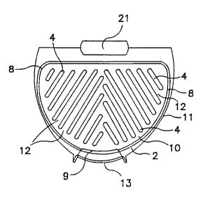
use or in a horizontal position. In figure 2 a top view of the novel cooking
surface 2 is
7
CA 02254041 1998-11-13
illustrated having diagonally positioned ribs 4 located thereon all pointing
toward the
drain peripheral channel 10 and eventually the drain 9. Each of the obliquely
positioned ribs 4 are rounded in a cross-sectional mode resembling a semi-
circle or less
as they protrude upwardly from surface 2. The important feature of the ribs 4
is that
they are rounded and extend slightly above the face of the horizontal plane of
the
cooking surface 2 as shown in figure SA; this provides an easy cleanable
cooking
surface. Ribs 4 must be diagonally positioned to allow easy draining toward
the
peripheral drain channel 10 and drain 9 and also provide spacing so that the
food
liquids pass in oblique drain channels or spaces 12 between each rib 4. On the
opposite
end of ribs 4 is a semi-circular or peripheral channel 10 located between the
end of ribs
4 and retaining wall 8. This channel 10 allows liquids to also flow through
this
peripheral channel 10 in addition to flowing through oblique channels 12
between ribs
4. Thus, because of the inclined surface of cooking surface 2, the oblique
channels 12
between the ribs 4, and the peripheral channel 10 adj acent to the retaining
wall 8, the
liquid grease easily flows down to drain 9 and empties into a grease
collection vessel 13
for eventual removal from the grill 1. The grease collection vessel 13 is
conveniently
located and removable from beneath the drain 9 by pulling on the front handle
18 of the
vessel which extends out from the lower grill portion. Whereas it can be easy
for meat
to slide down inclined surfaces with raised straight forward ribs as in Boehm
5,606,905,
making the ribs 4 diagonal as in the present invention substantially reduces
the sliding
on an inclined cooking surface 2. However, the retaining wall 8 in cooperation
with
diagonal ribs 4 ensures that foods will substantially stay in position. Again,
rounding
ribs 4 with low profiles as shown in figures 5 and SA makes cleaning cooking
surface 2
much easier, since there are no sharp rib angles or narrow crevices from which
grease
8
CA 02254041 1998-11-13
needs to be removed. The retaining wall 8 also keeps the meat from contacting
the
inside of the lid or grill housing thereby substantially eliminating another
possible
cleaning area. In figure 3 a breakaway side section of grill 1 is shown so
that most of
the internal components can be seen; some components such as the entire
retaining wall
are not shown for clarity in illustrating the other grill components. Grill 1
is shown
closed and it has an upper lid 3 which has an inner lid cooking surface 14 or
plate 14.
This surface 14 has projecting lid ribs 15 which are identical to cooking
surface ribs 4
except they are a minor image of ribs 4 (as shown in figure 4). When tapered
lid 3 is
closed, its interior is spaced from the cooking surface 2 to provide thereby a
cooking
chamber or space 16 which allows for the thickness space of the meat or food
being
cooked. An electric heating element 17 is located abutting or in the lid 3 and
in or
abutting the cooking surface 2 so that both surfaces cook the meat or food in
contact
therewith. The tapered cooking surface 2 terminates at its front portion with
a drain 9
through which the liquid grease will flow into a grease catcher or collection
vessel 13.
This collection vessel 13 can easily be removed by pulling handle 18 thereby
sliding
collection vessel 13 out from grill 1 so it may be emptied. A heat sensor
signal light 19
could be positioned on the upper outside face of lid 3 to indicate when the
food is
cooked, or temperature, etc. A portion of the retaining wall 8 can be seen on
the back
portion cooking surface 2. A hinge component 21 for lifting or closing the lid
3 is
shown but can be of any suitable structure. Grill 1 can be made of any
suitable material
such as plastic for the housing and good conducting materials such as steel or
metal for
lid inner surface 14 and cooking surface 2. Of course handles such as handle
18 are
made from non-conductive materials such as plastics, etc. In figure 4 ribs 4
on the
inner lid 3 and inclined cooking surface 2 (by "inclined" is meant a surface
that slants
9
CA 02254041 1998-11-13
downwardly from the back to front, with lowest portion in front) are
coextensive with
each other and are configured so that each will contact the steak or food
being grilled.
When the lid 3 is closed, a cooking compartment is formed with finger-like
ribs 4 and
channels 10 and 12 formed for cooking the meat and providing channels for
liquids to
flow to the drain 9. With the inclined cooking surface 2 and the channels 10
and 12
greases and other liquids are easily separated from the meat or food being
grilled. The
main housing contains a base 11, which is shown substantially horizontally
parallel to a
table 20 or other support surface. Central foot 7 and end foot 6 which are
made from
rubber or other suitable material contact table 20 in supporting grill 1. In
figure 5 a
portion of cooking surface 2 is shown with attention given to the
configuration of
1 S rounded ribs 4 and channels 12 between said ribs 4. The ribs 4 all point
toward drain 9
and thereby direct all liquids to the drain 9. A semi-circular channel 10
located
between retaining wall 10 and ribs 4 also directs liquids to drain 9. Figure
SA shows a
front plan view of the low profile ribs 4 on cooking surface 2. A critical
feature of this
invention is the rounded diagonally disposed ribs 4 all point toward the drain
peripheral
channel 10 which directs liquids ultimately to the drain 9. Another critical
feature of
the present invention is the retaining wall 8 which has two functions - - one
to hold the
meat in position and two from peripheral drain channel 10 to facilitate and to
direct all
juices or liquids to the drain 9. The low oblique profile ribs 4 assist in
holding the meat
in position and provide easy cleaning because of the lack or absence of deep
crevices or
cracks where grease can easily collect. Figure 6 shows the grill 1 when it is
stored in a
vertical position so as to take up less space in a storage area.
In Figure 7 the cooking surface 2 is shown with diagonal ribs 4 all directed
or
pointing toward peripheral drain channel 10 and liquid drain 9. Liquid drain 9
is an
CA 02254041 1998-11-13
arch shaped or concave curved opening in the front surface of cooking surface
2 which
conveys the drained fats or liquids from the peripheral channel 10 and oblique
channels
12 to a liquid collection vessel 13 that is beneath the drain 9. The
collection vessel 13
is slidably located in the undersurface of cooking surface 2 immediately under
the drain
9.
The preferred and optimumly preferred embodiments of the present invention
have been described herein and shown in the accompanying drawings to
illustrate the
underlying principles of the invention, but it is to be understood that
numerous
modifications and ramifications may be made without departing from the spirit
and
scope of this invention.
11