Note: Descriptions are shown in the official language in which they were submitted.
CA 02254105 2006-09-18
71932-46
1
CUSHIONING CONVERSION MACHINE AND METHOD
The present invention relates to a cushioning conversion machine and method in
which the cross-sectional geometry of a pad may be selectively varied.
BACKGROUND OF THE INVENTION
In the process of shipping an item from one location to another, a protective
packaging material is typicaliy placed in the shipping case, or box, to fill
any voids and/or to
cushion the item during the shipping process. Some conventional commonly used
protective packaging materials are plastic foam peanuts and plastic bubble
pack. While
these conventional plastic materials seem to adequately perform as cushioning
products,
they are not without disadvantages. Perhaps the most serious drawback of
plastic bubble
wrap and/or plastic foam peanuts is their effect on our environment. Quite
simply, these
plastic packaging materials are not biodegradable and thus they cannot avoid
further
multiplying our planet's already critical waste disposal problems. The non-
biodegradability
of these packaging materials has become increasingly important in light of
many industries
adopting more progressive policies in terms of environmental responsibility.
These and other disadvantages of conventional plastic packaging materials has
made paper protective packaging material a very popular alterative. Paper is
biodegradable, recyclable and renewable; making it an environmentally
responsible choice
for conscientious industries. While paper in sheet form could possibly be used
as a
protective packaging material, it is usijaliy preferable to convert the sheets
of paper into a
relatively low density pad-like cushioning dunnage product. This conversion
may be
accomplished by a cushioning conversion machine, such as that disclosed in
U.S. Patent
No. 5,322,477.
In a cushioning conversion machine which forms sheet-like stock material into
a
continuous strip, the cross-sectional geometry (i.e., the width) of the strip
essentially
dictates the cross-sectional geometry (i.e., the width) of the resulting
cushioning product.
For example, in the cushioning conversion machine disclosed in U.S. Patent No.
5,322,477, the cross-sectional geometry of the cushioning product, and
specifically its
width, is determined by the machine's forming assembly, and more particularly
a chute, and
even more particularly, the exit end of the chute.
In the commercial embodiments of the cushioning conversion machine disclosed
in
U.S. Patent No. 5,322,477, the cushioning product is about 8 to 10 inches in
width. This
pad size is acceptable and suitable, and even preferred, for many packaging
applications.
CA 02254105 1998-11-10
WO 98/40204 PCTIUS98/04655
2
However, occasionally, a slightly smaller width pad (i.e., 71/2 inches) is
required to
accommodate certain packaging applications. Additionally, especially in
sophisticated
packaging systems, pads of differing widths may be required, or at least
desired, to
package articles of differing dimensions and shapes.
U.S. Patent Nos. 4,884,999; 5,061,543 and 5,188,581 disclose a cushioning
conversion machine/method for making a cushioning product having a width of
about 3'/Z to
4 inches. The disclosed machine/method is the result of a revamping of a
"standard"
cushioning conversion machine into a machine capable of producing the
relatively narrow
cushioning product from fifteen-inches wide (as opposed to the thirty-inch
wide) stock
material. This revamping is accomplished by a kit which includes a funnel
member,
substantially smaller in cross-sectional dimensions than the converging chute,
and an
elongated bar-like member. To revamp the machine, the forming frame would be
removed, as it is not used to produce the narrow width cushioning product. The
converging
chute would likewise not be used during the narrow width pad production, but
it could either
be left on the machine or removed. The components of the kit (the narrow
funnel member
and the bar-like member) are then installed on the machine, and once
installed, the
revamped machine can be used to produce narrow width pads. If it is desired to
return to
the original sized pads, the kit components are removed and replaced with the
original
components to return the machine to full size production.
Thus, in the past, to the extent that the cross-sectional geometry of a
cushioning
pad has been changed, this change was accomplished by the replacement of
forming
assembly components. Thus, if a different width pad (i.e., 7% inches, 7
inches, 6'/h inches,
6 inches, 5'/z inches, etc.) is required, an alternate forming assembly would
have to be
supplied, for each desired pad width. Needless to say, the complications of
such a system
would place a strain on machine manufacture. Also, continuous revamping of
machines to
provide different width pads would not be able to accommodate sophisticated
packaging
systems which require pads of differing widths to package articles of
differing dimensions
and shapes.
SUMMARY OF THE INVENTION
The present invention provides a cushioning conversion machine including a
device
for selectively adjusting the cross-sectional geometry of a cushioning pad
produced by a
cushioning conversion machine. This adjustment may be accomplished without the
replacement of forming assembly components and allows a large range of
adjustments.
Additionally or alternatively, the cushioning conversion machine is able to
accommodate
CA 02254105 1998-11-10
WO 98/40204 PCT/US98/04655
3
sophisticated packaging systems which require pads of differing widths to
package articles
of differing dimensions and shapes.
In the preferred form of the invention, the cushioning conversion machine
comprises a forming assembly which forms sheet-like stock material into a
strip; a feed
assembly which advances the stock material through the forming assembly; and a
device
which controls the width of the strip and which may be selectively adjusted to
change the
width of the strip.
The preferred device includes a pair of guide members and a mounting assembly
mounting the guide members relative to the machine's frame. The preferred
forming
assembly includes a chute and the preferred feed assembly includes a pair of
rotating feed
members. The mounting assembly positions the guide members between the output
of
the chute and the rotating feed members and allows selective adjustment of the
spacing
between the guide members.
The mounting assembly preferably allows selective adjustment of the guide
member
spacing between a distance which is the same or greater than the width of the
exit end of
the chute and a distance which is less than the width of the exit end of the
chute. More
preferably, the mounting assembly allows selective adjustment of the guide
member
spacing to a plurality of distances which are less than the width of the exit
end of the chute.
In certain preferred embodiments of the invention, the guide members are
rollers
which are rotatably mounted on the mounting assembly whereby they may freely
turn as
the strip passes therethrough. The rollers have a concave shape and more
specifically
have a spool shape with an axial dimension approximately equal to the height
of the exit
end of the chute and positioned to surround the lateral edges of the strip as
it emerges from
the chute. In another preferred embodiment, the mounting assembly is fixed
relative to
the machine's frame and the guide members are selectively positionable on
(although non-
rotatably supported by) the fixed mounting assembly.
In certain preferred forms of the invention, the pad-adjustment device
includes at
least one adjustment member which is moved among a plurality of positions to
change the
width of the strip and the device includes a motorized drive, such as a
reversible rotary
motor, which moves the adjustment member among the plurality of positions. The
cushioning conversion machine may additionally comprise a control system for
controlling
the motorized drive to move the adjustment member among the plurality of
positions.
In a preferred method of converting sheet-like stock material into a three-
dimensional cushioning product according to the present invention, the sheet-
like stock
CA 02254105 2006-09-18
71932-46
4
material is supplied to the cushioning conversion machine.
The stock material is converted into a strip of a certain
width, the pad-adjustment device is adjusted, and the stock
material is converted into a strip of different width. Such
a method will produce a cushioning product according to the
present invention which has continuous portions of different
widths. The converting and adjusting steps may be performed
sequentially and in such a manner that the cushioning
product according to the present invention has discrete
sections of different widths. Alternatively, the converting
and adjusting steps may be performed substantially
simultaneously and in such a manner that the cushioning
product according to the present invention has a gradually
tapering shape.
In another preferred method of converting sheet-
like stock material into a three-dimensional cushioning
product according to the present invention, sheet-like stock
material is formed into a first strip of a certain width by
inwardly turning the lateral edges of the sheet-like stock
material and then the first strip is formed into another
strip of a less width by inwardly turning the outer lateral
sides of the first strip. The second forming step may be
accomplished by a pad-adjustment device according to the
present invention. In any event, a cushioning product is
produced which comprises two lateral pillow-like portions,
each including inwardly turned lateral edges of the sheet-
like stock material which have once again been inwardly
turned.
According to one aspect of the present invention,
there is provided a cushioning conversion machine for
converting sheet-like stock material into a three-
dimensional cushioning product, said machine comprising: a
forming assembly which forms the sheet-like stock material
CA 02254105 2006-09-18
71932-46
4a
into a strip; a feed assembly which advances the stock
material through the forming assembly; and a device which
controls the width of the strip and which is selectively
adjusted to change the width of the strip.
According to still another aspect of the present
invention, there is provided a method of converting sheet-
like stock material into a three-dimensional cushioning
product, said method comprising the steps of: supplying a
sheet-like stock material; forming the sheet-like stock
material into a first strip of a certain width by inwardly
turning the lateral edges of the sheet-like stock material;
and forming the first strip into another strip of a less
width by inwardly turning the outer lateral sides of the
first strip, wherein said forming steps are performed by a
cushioning conversion machine comprising a forming assembly
which forms the sheet-like stock material into the first
strip, a stock supply assembly which supplies the sheet-like
stock material to the forming assembly, a feed assembly
which advances the stock material through the first forming
assembly, and a second forming assembly which forms the
first strip into the second strip, and wherein the second
forming assembly is a device which may be selectively
adjusted to change the width of the strip.
According to yet another aspect of the present
invention, there is provided a cushioning product including
two lateral pillow-like portions, each including inwardly
turned lateral edges of a sheet-like stock material which
have once again been inwardly turned, made by a conversion
process including forming the sheet-like stock material into
a first strip of a certain width by inwardly turning the
lateral edges of the sheet-like stock material and then
forming the first strip into another strip of a less width
by compressing the outer lateral sides of the first strip.
CA 02254105 2006-09-18
71932-46
4b
According to a further aspect of the present
invention, there is provided a cushioning product comprising
two lateral pillow-like portions, each including inwardly
turned lateral edges of a sheet-like stock material which
have once again been inwardly compressed.
According to yet a further aspect of the present
invention, there is provided a cushioning product made by a
conversion process in which sheet-like stock material is
made by forming the sheet-like stock material into a first
strip of a certain width by inwardly turning the lateral
edges of the sheet-like stock material and then forming the
first strip into another strip of a less width by inwardly
turning the outer lateral sides of the first strip, whereby
the cushioning product includes two lateral pillow-like
portions, each including inwardly turned lateral edges of
the sheet-like stock material which have once again been
inwardly turned.
According to still a further aspect of the present
invention, there is provided a cushioning product comprising
two lateral pillow-like portions, each including inwardly
turned lateral edges of a sheet-like stock material which
have once again been inwardly turned.
According to another aspect of the present
invention, there is provided a cushioning conversion machine
including a device for selectively varying the cross-
sectional geometry of a cushioning pad produced by the
machine wherein the device comprises a pair of members which
may be moved towards and away from each other to selectively
vary the cross-sectional geometry of cushioning pad.
CA 02254105 2006-09-18
71932-46
4c
DRAWINGS
Figure 1 is a side view of the cushioning
conversion machine 20 incorporating an adjustment device 400
according to the present invention, the machine being shown
positioned in a horizontal manner, loaded with stock
material, and with an outer housing side wall removed for
clarity of illustration.
Figure 2 is an opposite side view of the
cushioning conversion machine 20.
Figure 3 is a top plan view of the cushioning
conversion machine 20, without stock material being loaded
and as seen along line 3-3 in Figure 1.
Figure 4 is a schematic side view of the
adjustment device 400.
Figure 5 is a schematic top view of the adjustment
device 400, the device being shown positioned so that the
cushioning conversion machine 20 will produce a maximum
width pad.
Figure 6 is a schematic top view of the adjustment
device 400, the device being shown positioned so that the
cushioning conversion machine 20 will produce an
intermediate width pad.
CA 02254105 1998-11-10
WO 98/40204 PCT/US98/04655
Figure 7 is a schematic top view of the adjustment device 400, the device
being
shown positioned so that the cushioning conversion machine 20 will produce a
narrow pad.
Figure 8 is a schematic side view of another adjustment device 500 according
the
present invention which may be incorporated in the cushioning conversion
machine 20.
5 Figure 9 is a schematic top view of the adjustment device 500, the device
being
shown positioned so that the cushioning conversion machine 20 will produce a
maximum
width pad.
Figure 10 is a schematic top view of the adjustment device 500, the device
being
shown positioned so that the cushioning conversion machine 20 will produce an
intermediate width pad.
Figure 11 is a schematic top view of the adjustment device 500, the device
being
shown positioned so that the cushioning conversion machine 20 will produce a
narrow pad.
Figure 12 is a schematic side view of another adjustment device 600 according
the
present invention which may be incorporated into the cushioning conversion
machine 20.
Figure 13 is a schematic top view of the adjustment device 600, the device
being
shown positioned so that the cushioning conversion machine 20 will produce a
maximum
width pad.
Figure 14 is a schematic top view of the adjustment device 600, the device
being
shown positioned so that the cushioning conversion machine 20 will produce an
intermediate width pad.
Figure 15 is a schematic top view of the adjustment device 600, the device
being
shown positioned so that the cushioning conversion machine 20 will produce a
narrow pad.
Figure 16 is a schematic side view of another adjustment device 700 according
the
present invention which may be incorporated into the cushioning conversion
machine 20.
Figure 17 is a schematic top view of the adjustment device 700, the device
being
shown positioned so that the cushioning conversion machine 20 will produce a
maximum
width pad.
Figure 18 is a schematic top view of the adjustment device 700, the device
being
shown positioned so that the cushioning conversion machine 20 will produce an
intermediate width pad.
Figure 19 is a schematic top view of the adjustment device 700, the device
being
shown positioned so that the cushioning conversion machine 20 will produce a
narrow pad.
CA 02254105 1998-11-10
WO 98/40204 PCT/US98/04655
6
Figure 20 is a perspective view of a cushioning product or pad made when any
of
the adjustment devices 400, 500, 600 or 700 are positioned so that the
cushioning
conversion machine 20 will produce a maximum width pad.
Figure 21 is a perspective view of a cushioning product or pad made when any
of
the adjustment devices 400, 500, 600 or 700 are positioned so that the
cushioning
conversion machine 20 will produce a narrow pad.
Figure 22 is a schematic top view of a modified adjustment device 400', the
device
including a motorized drive.
Figure 23 is schematic side view of a modified adjustment device 600', the
device
including a motorized drive.
Figures 24A-24F are schematic views of various control systems according to
the
present invention for controlling a cushioning conversion machine including an
adjustment
device with a motorized drive.
Figure 25 is a perspective view of a cushioning product or pad according to
the
present invention.
Figure 26 is a perspective view of another cushioning product or pad according
to
the present invention.
DETAILED DESCRIPTION
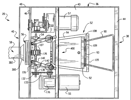
Referring now to the drawings in detail, and initially to Figures 1-3, a
cushioning
conversion machine 20 incorporating a pad adjustment device 400 according to
the present
invention is shown. The illustrated machine 20 is similar to that disclosed in
U.S. Patent
No. 5,322,477. However, an adjustment device according to the present
invention may be
incorporated into any cushioning conversion machine or method which falls
within the
scope of the claims. For example, the device may be incorporated into a
cushioning
conversion machine as set forth in U.S. Patent No. 4,968,291, (list senior
junior, etc.)
As is explained in more detail below, the pad adjustment device 400 is a a
device
for selectively adjusting the cross-sectional geometry of a cushioning pad
produced by a
cushioning conversion machine 20, particularly the width of the cushioning pad
in the
preferred embodiments. The pad-width adjustment may be accomplished without
the
replacement of forming assembly components and allows a large range of
adjustments.
Additionally or alternatively, the cushioning conversion machine 20 is able to
accommodate
sophisticated packaging systems which require pads of differing widths to
package articles
of differing dimensions and shapes.
CA 02254105 1998-11-10
WO 98/40204 PCT/US98/04655
7
In Figures 1 and 2, the cushioning conversion machine 20 is shown positioned
in a
horizontal manner and loaded with a roll 21 of sheet-like stock material 22.
The stock
material 22 may consist of three superimposed webs or layers 24, 26, and 28 of
biodegradable, recyclable and reusable thirty-pound Kraft paper rolled onto a
hollow
cylindrical tube 29. A thirty-inch roll of this paper, which is approximately
450 feet long, will
weigh about 35 pounds and will provide cushioning equal to approximately four
15 ff bags
of plastic foam peanuts while at the same time requiring less than one-
thirtieth the storage
space.
The machine 20 converts this stock material 22 into a continuous unconnected
strip
having lateral pillow-like portions separated by a thin central band. This
strip is connected
along the central band to form a connected strip which is cut into sections 32
of a desired
length. The cut sections 32 each include lateral pillow-like portions 33
separated by a thin
central band and provide an excellent relatively low density pad-like product
which may be
used instead of conventional plastic protective packaging material.
The machine 20 includes a housing, indicated generally at 36, having an
upstream
or "feed" end 38 and a downstream or "discharge" end 40. The terms "upstream"
and
"downstream" in this context are characteristic of the direction of flow of
the stock material
22 through the machine 20. The housing 36 is positioned in a substantially
horizontal
manner whereby an imaginary longitudinal line or axis 42 from the upstream end
38 to the
downstream end 40 would be substantially horizontal.
The housing 36 includes side walls 37, a top or cover wall 39, a base plate or
wall
43 and two end walls 44 and 46. The frame base wall 43 is generally
rectangular and
extends from the upstream end 38 to the downstream end 40 of the housing 36 in
a
generally horizontal plane. Although not perfectly apparent from the
illustrations, the first or
upstream wall 44 may be more specifically described as a thin rectangular wall
having a
rectangular stock inlet opening 47 passing therethrough. Alternatively,
instead of the end
wall 44, the side and base walls 37 and 43 may have upstream inwardly turned
end
sections that form a rectangular border around the stock inlet opening 47. The
second or
downstream end wall 46 is generally rectangular and planar and includes a
relatively small
rectangular outlet opening.
The first frame end wall 44 extends generally perpendicular in one direction
from
the upstream end of the frame base wall 43. In the illustrated embodiment of
Figures 1 and
2, this direction is upward. The second end wall 46 is preferably aluminum and
extends in
generally the same perpendicular direction from the downstream end of the
frame base
CA 02254105 1998-11-10
WO 98/40204 PCT/US98/04655
8
wall 43. In this manner, the housing 36 is basically "C" shape and one side of
the frame
base wall 43, which in this embodiment is the lower side, is a flat
uninterrupted surface.
The housing 36 also includes a box-like extension 49 removably attached to a
downstream
portion of the base wall 43. Although not shown in all of the drawings, the
frame may be
enclosed by a sheet metal housing, including side walls 37 and a top wall or
cover 39.
The machine 20 further includes a stock supply assembly 50, a forming assembly
52, a feed assembly 54 powered by a feed motor 55, a cutting assembly 56
powered by a
cutter motor 57, and a post cutting assembly 58. In operation of the machine
20, the stock
supply assembly 50 supplies the stock material 22 to the forming assembly 52.
The
forming assembly 52 causes inward rolling of the lateral edges of the sheet-
like stock
material 22 to form the lateral pillow-like portions 33 of the continuous
strip. The feed
assembly 54 pulls the stock material 22 from the stock roll 21, through the
stock supply
assembly 50, and through the forming assembly 52 and also connects or stitches
the
central band of the strip to form the connected strip. As the connected strip
travels
downstream from the feed assembly 54, the cutting assembly 56 cuts the strip
into sections
32 of a desired length. These cut sections 32 then travel through the post-
cutting assembly
58.
Turning now to the details of the various assemblies, the stock supply
assembly 50
includes two laterally spaced brackets 62. The brackets 62 are each generally
shaped like
a sideways "U" and have two legs 64 and 65 extending perpendicularly outward
from a flat
connecting base wall 66. (See Figures 1 and 2.) For each bracket 62, the base
wall 66 is
suitably secured to the downstream side of the frame end wall 44, such that
the leg 64 is
generally aligned with the frame base wall 43. Both of the legs 64 have open
slots 70 in
their distal end to cradle a supply rod 72. The supply rod 72 is designed to
extend
relatively loosely through the hollow tube 29 of the stock roll 21. As the
stock material 22 is
pulled through the machine 20 by feed assembly 54, the tube 29 will freely
rotate thereby
dispensing the stock material 22. A pin (not shown) may be provided through
one or both
ends of the supply rod 72 to limit or prevent rotation of the supply rod 72
itself.
The other legs 65 of the U-brackets 62 extend from an intermediate portion of
the
frame end wall 44 and cooperate to mount a sheet separator, indicated
generally at 74.
The sheet separator 74 includes three horizontally spaced relatively thin
cylindrical
separating bars 76, 77 and 78. The number of separating bars, namely three,
corresponds
to the number of paper layers or webs of the stock material 22. The sheet
separator 74
separates the layers 24, 26 and 28 of paper prior to their passing to the
forming assembly
CA 02254105 2006-09-18
71932-46
9
52. This "pre-separation" is beiieved to improve the resiliency of the
produced dunnage
product. Details of a separating mechanism similar to the separator 74 are set
forth in U.S.
Patent No. 4,750,896.
The bracket legs 65 also cooperate to support a constant-entry bar 80 which is
rotatably mounted on the distal ends of the legs. The bar 80 provides a non-
varying point
of entry for the stock material 22 into the separator 74 and forming assembly
52, regardless
of the diameter of the stock roll 21. Thus, when a different diameter roll is
used and/or as
dispensation of the stock material 22 from roll 21 decreases its diameter, the
point of entry
of the stock material 22 into the separator 74 remains constant. This
consistency facilitates
the uniform production of cushioning dunnage. Details of a rolier member" or a
"bar
member" similar to the constant-entry bar 80 are set forth in U.S. Patent No.
4,750,896.
After the stock material 22 is pulled from the stock roll 21 over the constant-
entry
bar 80 and through the sheet separator 74, it is pulled through the stock
inlet opening 47 to
the forming assembly 52. The forming assembly 52 includes a three-dimensional
bar-like
shaping member 90 (or forming frame), a converging chute 92, a transverse
guide
structure 93 and a guide tray 94. The stock material 22 travels between the
shaping
member 90 and the frame base wall 43 until it reaches the guide tray 94. At
this point, the
transverse guide structure 93 and the guide tray 94 guide the stock material
22
longitudinally and transversely into the converging chute 92. During this
downstream
travel, the shaping member 90 rolls the edges of the stock material 22 to form
the lateral
pillow-like portions 33 and the converging chute 92 coacts with the shaping
member 90 to
form the continuous strip. As the strip emerges from the converging chute 92,
the guide
tray 94 guides the strip into the feed assembly 54.
The shaping member 90 is a three-dimensional forming frame having a V-Iike, in
plan body and generally U-shaped, in end elevation, ribs extending downwardly
from and
generally transverse to the body portion. Further structural detaiis of the
shaping member
90 or "forming frame' are set forth in U.S. Patent No. 4,750,896.
The guide tray 94 is directly mounted on the frame base wall 43; while the
transverse guide structure 93 and the converging chute 92 are mounted on the
guide tray
94. The guide tray 94 is trapezoidal in shape, as viewed in plan, having a
broad upstream
side 105 and a parallel narrow downstream side 106. The broad side 105 is
positioned
downstream of at least a portion of the shaping member 90. The narrow side 106
is
positioned adjacent the outiet opening in the frame end wall 46 and includes a
rectangular
CA 02254105 2006-09-18
71932-46
slot 107 to accommodate the feed assembly 54. The guide tray 94 is not
positioned
parallel with the frame base wall 43, but rather slopes away (upwardly in
Figures 1 and 2)
from the frame base wall 43 to the feed assembly 54.
The converging chute 92 is mounted on the guide tray 94 upstream of at least a
5 portion of the shaping member 90 and downstream slightly from the broad side
105 of the
guide tray 94. The transverse guide structure 93 is mounted on the guide tray
94 just
upstream of the entrance mouth of the converging chute 92. The transverse
guide
structure 93 includes rollers 108 rotatably mounted on a thin U-bracket 109.
The distal
ends of the U-bracket 109 are secured to the guide tray 94. Except for this
mounting
10' arrangement, the transverse guide structure 93 is similar to the "rollers
and wire frame"
disciosed in U.S. Patent No. 4,750,896.
With the guide tray 94 and the transverse guide structure 93 mounted in this
manner, the stock material 22 travels over the guide tray 94, under the
upstream end of the
shaping member 90, between the rollers 108 of the transverse guide structure
93, and into
the converging chute 92. The basic cross-sectional geometry and functioning of
the
converging chute 92 is similar to that of the converging member described in
U.S. Patent
No. 4,750;.896.
Alternatively, the forming assembly 52 may include
the chute and/or the shaping member disclosed in
U.S. Patent No. 5,709,642. Such a chute has an inlet
end which is outwardly flared in a
trumpeted fashion to faciiitate passage of the stock material into the shaping
chute: (The
trumpet-like inlet may eliminate the need for the transverse guide structure
93.) Such a
shaping member is longitudinally formed into a U-shape comprised of a first
leg attached to
a top wall of the chute and a second leg extending into the chute generally
parallel with the
bottom wall of the chute.
The stock material 22 will emerge from the chute 92 as the continuous
unconnected
strip. The emerging strip is guided to the feed assembly 54 by the narrow
downstream end
106 of the guide tray 94, which extends from the outlet opening of the chute
to the outlet
opening in the frame end waI146. The feed assembly 54 includes rotating feed
members
between which the stock material 22 travels, specifically loosely meshed
horizontally
arranged drive gear 124 and idler gear 126. When the gears 124 and 126 are
turned the
appropriate direction, which in Figure 1 would be counterclockwise for gear
124 and
ciockwise for gear 126, the central band of the strip is grabbed by the gear
teeth and pulled
CA 02254105 2006-09-18
71932-46
11
downstream through the nip of gears 124 and 126. This same "grabbing" motion
caused
by the meshing teeth on the opposed gears 124 and 126 simultaneously
compresses or
"coins" the layers of the central band together thereby connecting the same
and forming
the connected strip.
The drive gear 124 is positioned between the frame base wall 43 and the guide
tray
94 and projects through the rectangular slot 107 in the guide tray 94. The
gear 124 is
fixediy mounted to a shaft 130 which is rotatably mounted to the upstream side
of the frame
end wall 46 by bearing structures 131. A sprocket 132 at one end of the shaft
accommodates a chain 133 which connects the shaft 130 to a speed reducer 136.
The
speed reducer 136 acts as an interface between the feed assembly 54 and the
feed motor
55 for controlling the rate of "pulling" of the stock material 22 through the
machine 20. As is
best seen in Figure 1, the feed motor 55 and the speed reducer 136 are mounted
on the
frame base wall 43 at approximately the same level as the forming assembly 52.
The idler gear 126 is positioned on the opposite side of the guide tray 94 and
is
rotatably mounted on a shaft 140. Shaft brackets 142 attached to an upstream
side of the
frame end wall 46 non-rotatably support the ends of the shaft 140 in spring-
loaded slots
144. The slots 144 allow the shaft 140, and therefore the idler gear 126, to
"float" relative
to the drive gear 124 thereby creating an automatic adjustment system for the
feed
assembly 54.
Altematively, the automatic adjustment system for feed assembly 54 could be of
the
type disclosed in U.S. Patent No. 5,709,642. In such an adjustment system,
first and second tie members would be movably connected to the shaft 140 and
would
extend transversely with respect to the shaft 140. Each of the tie members
would have
one end in fixed transverse position relative to the machine's housing 36 and
an adjustable
stop which is selectively adjustable towards and away from the shaft 140. A
spring
member would be interposed between the shaft 140 and the adjustable stop to
resiliently
bias the shaft 140 towards the shaft 130. In this manner, the pinch force
applied by the
rotating feed members 124 and 126 could be adjusted without changing a minimum
set
distance between the shafts 130 and 140.
Additionally or alternatively, the rotating feed members 124 and 126 may be of
the
type contained in the stitching assembly disclosed in
U.S. Patent No. 6,035,613. In such a stitching assembly,
the first rotating feed member would have a plurality of
radially outwardly extending projections
CA 02254105 2006-09-18
71932-46
12
around its circumference and the projections would have at axially spaced
apart segments
defining a recess therebetween. The second rotating feed member would have
axial punch
segments which each include a peripheral edge portion for receipt into the
first member's
recesses. The peripheral edge portions would have opposite corners which are
cooperative with the first member's projections to cut a row of slits in the
overlapped
portions of the stock material to interlocking these overlapped portions.
In any event, the feed assembly 54 transforms the unconnected strip into the
connected strip and this strip travels through the outlet opening in the frame
end wall 46.
The connected strip is then cut by the cutting assembly 56 into cut sections
32 of the
10- desired length. The cutting assembly 56 may be of any suitable type, such
as the types
disclosed in U.S. Patent No. 5,123,899, the type disclosed
in U.S. Patent No. 6,311,596, and/or the type disclosed in
U.S. Patent No. 5,569,146. However, whatever type of
cutting or severing assembly is used, the connected strip is divided into cut
sections 32 of
the desired length and these cut sections 32 then travel downstream to the
post cutting
assembly 58.
The post-cutting assembly 58 is basically funnel-shaped and includes an
upstream
converging portion 300 which tapers into a downstream rectangular tunnel
portion 302.
The converging portion 300 is located between the downstream frame end wall 46
and the
extension 49, while the tunnel portion 302 extends through and beyond the
frame extension
49. The post-cutting assembly 58 is positioned so that its inlet 304 is
aligned with the outlet
opening of the end wall 46. The downstream outlet 306 of the post-cutting
assembly 58 is
also preferably aligned with the outlet opening and also the inlet 304.
A cut section 32 will be urged or pushed downstream into the inlet 304 of
assembly
58 by the approaching connected strip. The converging portion 300 smoothly
urges the
section 32 into the tunnel portion 302. A cut section 32 emerging from the
post-cutting
assembly 58 may be directed to a desired packing location, the conversion of
stock
material 22 to cut sections 32 of relatively low density pad-like cushioning
dunnage product
now being complete.
Turning now to Figures 4-7, the pad adjustment device 400 is shown in detail.
The
device 400 includes a pair of rollers 404 movably mounted to the machine
housing 36 by a
mounting assembly 406. The mounting assembly 406 positions the rollers 404
between
CA 02254105 1998-11-10
WO 98/40204 PCT/US98/04655
13
the output of the forming chute 92 and the feed gears 124/126. Thus, the
device 400 may
be viewed as forming an extension of the forming chute 92.
The device 400 allows selective adjustment of the spacing or distance D
between
the rollers 404. (Compare Figures 5, 6 and 7.) If the distance D between the
rollers 404 is
greater than the width of the exit end of the converging chute 92, the rollers
404 will have
littie or no contact with (and/or little or no effect on) the strip as it
passes therebetween.
(See Figure 5.) Thus, the width of the pad will be same as if the machine 20
did not
include the device 400. If the distance D between the rollers 404 is decreased
to less than
the width of the exit end of the converging chute, the rollers 404 compress
the strip into a
narrower form, thereby resulting in a narrower pad. (See Figure 6.) If the
distance D
between the rollers is decreased even more, an even narrower pad will be
produced. (See
Figure 7.)
The rollers 404 preferably have a concave spool shape with an axial dimension
approximately equal to the height of the exit of the converging chute 92. (See
Figure 4.)
Additionally, the rollers 404 are positioned so that their lower axial ends
are adjacent the
guide tray 94. In this manner, the concave surfaces of the rollers 404 will
surround the
lateral edges of the strip as it emerges from the converging chute 92. The
mounting
assembly 406 preferably rotatably supports the rollers 404 whereby they will
freely turn as
the strip passes therethrough.
The preferred mounting assembly 406 includes a pair of arms 408, and an
adjustment bar 410. The arms 408 each have one end pivotally mounted to the
end plate
46 via a pivotal coupling element 412. When the arms 408 are pivoted away from
each
other, pad width will be increased (or maximized) (see Figure 5) and when the
arms 408
are pivoted towards each other, pad width will be decreased (see Figures 6 and
7). In this
manner, slight variations in pad widths may be easily accomplished for use
with, for
example, sophisticated packaging systems.
The arms 408 each have an opposite end having a slot 414 which slidably
receives
a leg of an L-shaped cross bar 416. The cross-bar 416 is suspended between the
frame
side panels 37 and stabilizes the arms 408 by preventing them from moving up
and down
while still allowing the arms 408 to pivot relative to the machine's housing
36.
The adjustment bar 410 extends between distal portions of the arms 408 and may
be used to the determine or set the spacing between the rollers 404. The
adjustment bar
410 is fixedly secured to one arm 408 (the one positioned in the upper
portions of Figures
5-7) via a fixed bracket 417 and slidably secured to the other arm 408 via a
sliding bracket
CA 02254105 1998-11-10
WO 98/40204 PCT/US98/04655
14
418. Thus to adjust the spacing between the rollers 404 (and thus the pad
width), the
adjustment bar 410 is moved in a direction perpendicular to the upstream-
downstream
direction. Other means for adjusting the spacing between the rollers is
possible with, and
contemplated by, the present invention. For example, a threaded rod could be
provided
between the arms 408 for screwing/unscrewing to decrease/increase pad width.
The sliding bracket 418 includes a knob-locking screw 420 for receipt into
appropriately positioned apertures 422 in the bar 410. Although not
specifically shown on
the drawings, the apertures 422 define "locking positions" corresponding to
predetermined
pad widths, preferably in 1 inch intervals. (Note that the apertures 422
themselves will not
necessarily be spaced at exactly these intervals, as the relevant parameter is
the spacing
of the rollers 404.) Although also not specifically shown in the drawings, the
adjustment
bar 410 may include indicia identifying the aperture settings, and
particularly the pad widths
corresponding to the aperture settings.
Another device 500 for selectively adjusting the cross-sectional geometry of a
cushioning pad according to the present invention is shown in Figures 8-11.
The device 500 may be incorporated into the cushioning conversion machine 20,
or any
other cushioning conversion machine or method which falls within the scope of
the claims.
The device 500 includes a pair of rollers 504 movably mounted to the machine
housing 36 by a mounting assembly 506. The mounting assembly 506 positions the
rollers
504 between the output of the forming chute 92 and the feed gears 124/126.
Thus, the
device 500 may be viewed as forming an extension of the forming chute 92.
The device 500 allows selective adjustment of the spacing or distance D
between
the rollers 504. (Compare Figures 9, 10 and 11.) If the distance D between the
rollers 504
is greater than the width of the exit end of the converging chute 92, the
rollers 504 will have
little or no contact with (and/or little or no effect on) the strip as it
passes therebetween.
(See Figure 9.) Thus, the width of the pad will be same as if the machine 20
did not
include the device 500. If the distance D between the rollers 504 is decreased
to less than
the width of the exit end of the converging chute, the rollers 504 compress
the strip into a
narrower form, thereby resulting in a narrower pad. (See Figure 10.) If the
distance D
between the rollers is decreased even more, an even narrower pad will be
produced. (See
Figure 11.)
The rollers 504 preferably have a concave spool shape with an axial dimension
approximately equal to the height of the exit of the converging chute 92. (See
Figure 8.)
Additionally, the rollers 504 are positioned so that their lower axial ends
are adjacent the
CA 02254105 1998-11-10
WO 98/40204 PCT/US98/04655
guide tray 94. In this manner, the concave surfaces of the rollers 504 will
surround the
lateral edges of the strip as it emerges from the converging chute 92. The
mounting
assembly 506 preferably rotatably supports the rollers 504 whereby they will
freely turn as
the strip passes therethrough.
5 The preferred mounting assembly 506 includes a first pair of arms 508, a
second
pair of arms 509, an adjustment bar 510, and a slidably mount 511 for the
adjustment bar
510. The arms 508 each have one end pivotally mounted to the end plate 46 via
a pivotal
coupling element 512. When the arms 508 are pivoted away from each other, pad
width
will be increased (or maximized) (see Figure 9) and when the arms 508 are
pivoted
10 towards each other, pad width will be decreased (see Figures 10 and 11). In
this manner,
slight variations in pad widths may be easily accomplished for use with, for
example,
sophisticated packaging systems.
The arms 508 each have an opposite end having a slot 514 which slidably
receives
a leg of an L-shaped cross bar 516. The cross-bar 516 is suspended between the
frame
15 side panels 37 and stabilizes the arms 508 by preventing them from moving
up and down
while still allowing the arms 508 to pivot relative to the machine's housing
36.
The second pair of arms 509 are each pivotally connected at one end to a
distal
portion of respective arms 508. (See Figures 8-11.) The opposite ends of the
second pair
of arms is pivotally connected to one end of the adjustment bar 510. Thus, the
arms 508
and 509 form a four-arm linkage, the movement of which is controlled by the
adjustment
bar 510 to thereby determine or set the spacing between the rollers 504.
As was indicated above, one end of the adjustment bar 510 is connected to
corresponding ends of the arms 509. The opposite end of the adjustment bar 510
is
slidably mounted on the mount 511. To adjust the spacing between the rollers
504 (and
thus the pad width), the adjustment bar 510 is moved in a direction parallel
to the
upstream-downstream direction. The mount 511 may be coupled to the machine's
frame
via, for instance, a hanger 517, suspended from a cross-bar 518 extending
between the
machine's side panels 37.
The adjustment bar 510 preferably includes a knob-locking screw 520 for
receipt
into appropriately positioned apertures 522 in the mount 511. The apertures
522 define
"locking positions" corresponding to predetermined pad widths, preferably in
one inch
intervals. (Note that the apertures 522 themselves will not necessarily be
spaced at exactly
these intervals, as the relevant parameter is the spacing of the rollers 504.)
The mount
CA 02254105 1998-11-10
WO 98/40204 PCT/US98/04655
16
511 also may include indicia identifying the aperture settings, and
particularly the pad
widths corresponding to the aperture settings
Another device 600 for selectively adjusting the cross-sectional geometry of a
cushioning pad produced by a cushioning conversion machine according to the
present
invention is shown in Figures 12-15. The device 600 may be incorporated into
the
cushioning conversion machine 20, or any other cushioning conversion machine
or method
which falls within the scope of the claims.
The device 600 includes a pair of rollers 604 movably mounted to the machine
housing 36 by a mounting assembly 606. The mounting assembly 606 positions the
rollers
604 between the output of the forming chute 92 and the feed gears 124/126.
Thus, the
device 600 may be viewed as forming an extension of the forming chute 92
and/or a
second forming assembly.
The device 600 allows selective adjustment of the spacing or distance D
between
the rollers 604. (Compare Figures 13, 14 and 15.) If the distance D between
the rollers
604 is greater than the width of the exit end of the converging chute 92, the
rollers 604 will
have little or no contact with (and/or little or no effect on) the strip as it
passes
therebetween. (See Figure 13.) Thus, the width of the pad will be same as if
the machine
did not include the device 600. If the distance D between the rollers 604 is
decreased to
less than the width of the exit end of the converging chute, the rollers 604
compress the
20 strip into a narrower form, thereby resulting in a narrower pad. (See
Figure 14.) If the
distance D between the rollers is decreased even more, an even narrower pad
will be
produced. (See Figure 15.)
The rollers 604 preferably have a concave spool shape with an axial dimension
approximately equal to the height of the exit of the converging chute 92. (See
Figure 12.)
Additionally, the rollers 604 are positioned so that their lower axial ends
are adjacent the
guide tray 94. In this manner, the concave surfaces of the rollers 604 will
surround the
lateral edges of the strip as it emerges from the converging chute 92. The
mounting
assembly 606 preferably rotatably supports the rollers 604 whereby they will
freely turn as
the strip passes therethrough.
The preferred mounting assembly 606 includes a first pair of arms 608, a
second
pair of arms 609, an adjustment bar 610, and a mount 611 for the adjustment
bar 610.
The arms 608 each have one end pivotally mounted to the end wall 46 via a
pivotal
coupling element 612. When the arms 608 are pivoted away from each other, pad
width
will be increased (or maximized) (see Figure 13) and when the arms 608 are
pivoted =
CA 02254105 1998-11-10
WO 98/40204 PCT/US98/04655
17
towards each other, pad width will be decreased (see Figures 14 and 15). In
this manner,
slight variations in pad widths may be easily accomplished for use with, for
example,
sophisticated packaging systems.
The second pair of arms 609 are each pivotally connected at one end to a
distal
portion of respective arms 608. (See Figures 12-16.) The opposite ends of the
second
pair of arms is pivotally connected to one end of the adjustment bar 610. A
spacer 614 is
provided so that the arms 609 may be stacked one on top of the other. Thus,
the arms
608 and 609 form a four-arm linkage, the movement of which is controlled by
the
adjustment bar 610 to thereby determine or set the spacing between the rollers
604. Also,
the rollers 604 are simultaneously moved uniform distances to insure proper
placement
relative to the exit of the chute 92 and/or the feed gears 124/126.
As was indicated above, one end of the adjustment bar 610 is connected to
corresponding ends of the arms 609. The opposite end of the adjustment bar 610
is
slidably mounted on the mount 611. !n the illustrated orientation, the
adjustment bar 610 is
vertically positioned so that its lower end is connected to the arms 609 and
its upper end is
slidably received in the mount 611. Specifically, the slidable mount 611 is
attached to the
inner side of the machine's top wall 39 and includes a slot through which a
knob 620
extends. The knob 620 is connected to the top end of the bar 610. To adjust
the spacing
between the rollers 604 (and thus the pad width), the knob 620 (and thus the
adjustment
bar 610) is moved in a direction parallel to the upstream-downstream
direction. The top
cover 39 may include indicia identifying settings for the knob 620 which
correspond to
particular pad widths. Thus, the device 600 includes a control element which
is situated
outside the housing of the cushioning conversion machine whereby the machine
housing
need not be opened to vary the cross-sectional geometry, or width, of the
cushioning pad.
Another device 700 for selectively adjusting the cross-sectional geometry of a
cushioning pad produced by a cushioning conversion machine is shown in Figures
16-19.
The device 600 may be incorporated into the cushioning conversion machine 20,
the
cushioning conversion machine disclosed in U.S. Patent No. 4,968,291, and/or
any
cushioning conversion machine or method which falls within the scope of the
claims.
The device 700 includes a pair of guide members 704 mounted to the machine
frame 36 by a mounting assembly 706. The mounting assembly 706 positions the
guide
members 704 between the output of the forming chute 92 and the feed gears
124/126.
Thus, the device 700 is positioned to guide the stock material as it travels
between the
forming assembly 52 and the feed assembly 54.
CA 02254105 1998-11-10
WO 98/40204 PCT/US98/04655
18
The guide members 704 preferably have a smooth cylindrical shape with an axial
dimension approximately equal to the height of the exit of the converging
chute 92. (See
Figure 16.) Additionally, the guide members 704 are positioned so that their
lower axial
ends are adjacent the guide tray 94. In this manner, the cylindrical surfaces
of the guide
members 704 will guide the lateral edges of the strip as it emerges from the
converging
chute 92.
The guide members 704 have an axially extending core 705 through which
components of the mounting assembly 706 extend to non-rotatably support the
guide
members 704. The cores 705 are eccentrically (i.e., non centrally located) on
each of the
guide members 704. In this manner, the device 700 is designed to allow
selective
adjustment of the spacing or distance between the guide members 704. (Compare
Figures
17, 18 and 19.) When the guide members 704 are positioned so that the distance
between the outer circumference of the guide members 704 is a distance
approximately
equal to the width of the exit end of the converging chute 92, the guide
members 704 will
guide the strip as in a non-converging path as it passes therebetween. (See
Figure 17.)
Thus, the width of the pad will be same as if the machine 20 did not include
the device 700.
When the guide members are positioned so that the distance between the outer
circumference of the guide members 704 is decreased to less than the width of
the exit end
of the converging chute 92, the guide members 704 guide the strip and compress
it into a
narrower form, thereby resulting in a narrower pad. (See Figure 18.) When the
guide
members 704 are positioned so that the distance between the outer
circumference of the
guide members 704 is at a minimum distance, the guide members 704 guide the
strip and
compress it into an even narrower form. (See Figure 19.)
The preferred mounting assembly 706 includes is bar-shape member having a goal
post, or U-shape geometry. Thus, the preferred mounting assembly 706 includes
a bottom
member 708, and two vertically extending posts 709. The bottom member 708 is
preferably positioned below the mounting tray 94 and attached thereto by a
mounting
bracket 710. The vertical posts 709 extend through openings in the mounting
tray 92 and
the guide members 704 are non-rotatably mounted thereon. The mounting assembly
706
preferably includes locating structure to lock the guide members 704 in the
selected
position. For example, the top ends of the vertical posts 709 may be threaded
whereby a
locking member 711 may be used to lock the guide member in the desired
positioning
relative to the vertical posts 709.
CA 02254105 1998-11-10
WO 98/40204 PCT/US98/04655
19
When the device 400, 500, 600 or 700 is one of the narrower-width settings,
the
machine 20 essentially performs a two-step forming process on the stock
material.
Specifically, the sheet-like stock material is formed into a first strip y of
a certain width by
inwardly turning the lateral edges of the sheet-like stock material in the
forming assembly
52. (Figure 20.) The strip S, includes two lateral pillow-like sections 1000
and a central
connecting section 1002. This first strip S, is then formed into another strip
SZ of a less
width by inwardly compressing the outer lateral sides of the first strip S; by
the device 700.
(Figure 21.) The resulting cushioning product P comprises two lateral pillow-
like portions
1000, each including inwardly turned lateral edges of the sheet-like stock
material which
have once again been inwardly compressed. (Figure 21.)
A modified version 400' of the device 400 is shown in Figure 22. (The same
reference numerals are used to designate identical components, "primed"
reference
numerals are used to designate analogous, but modified, components, and new
reference
numerals are used to designate new components.). The device 400' includes a
motorized
drive 426 for adjusting the spacing between the rollers 404 (and thus the pad
width) by
rotating the adjustment bar 410'. The motorized drive 426 is preferably a
reversible
electrical motor 427 having a shaft 428 coupled to a threaded adjustment rod
410' of the
modified mounting assembly 406.' The rod 410' has external left-hand screw
treads on one
side and external right-hand screw treads on the other side. Brackets 418'
(attached to
the arms 408) have corresponding internal screw treads. The brackets 418'
include
diagonal slots to allow the arms 408 to be moved inwardly and outwardly
without
movement of the rod 410'.
The motorized drive 426 may be manually activated (i.e., a push button is held
down for a particular period of time). When the motor shaft 428 (and thus the
adjustment
rod 410') is rotated in one direction, the brackets 418' (and thus the arms
408 and the
rollers 404) are moved inwardly. When the motor shaft 428 is rotated in the
opposite
direction, the brackets 418 are moved outwardly. If desired, the adjustment
rod 410' may
be mounted to the cross-bar 416 by a bearing structure 430.
A modified version 600' of the device 600' is shown in Figure 23. (The same
reference numerals are used to designate identical components, "primed"
reference
numerals are used to designate analogous, but modified, components, and new
reference
numerals are used to designate new components.) The device 600' includes a
motorized
drive 626 for adjusting the spacing between the rollers 604 (and thus the pad
width) by
moving the adjustment bar 610' in a direction parallel to the upstream-
downstream
CA 02254105 1998-11-10
WO 98/40204 PCT/US98/04655
direction. The motorized drive 626 is preferably a reversible electric motor
627 having a
shaft 628 coupled to a feed screw 629. The adjustment bar 610' includes a
threaded
opening which receives the feed screw 629.
The motorized drive 626 may be manually activated (i.e., a push button is held
5 down for a particular period of time). When the motor shaft 628 (and thus
the feed screw
629) is rotated in one direction, the adjustment bar 610' is moved downstream
and the
arms 609 (and thus the arms 608 and the rollers 604) are moved inwardly. When
the
motor shaft 628 is rotated in the opposite direction, the adjustment bar 610'
is moved
upstream and the rollers 604 are moved outwardly.
10 As was indicated above, the motorized drive 426 and/or 626 may be manually
activated. Alternatively, to automatically control the motorized drives 426,
626, or any other
motorized drive which moves a pad width adjustment device, the cushioning
conversion
machine 20 may include one or more of the control systems shown in Figures 24A-
24F.
In the control system shown in Figure 24A, the machine's internal controller
900 (i.e.
15 a microprocessor) is operably coupled to the motorized drive 426/626, the
feed assembly
54, and the cutting assembly 56. The controller 900 includes an input 902 for
the pad
width, an input 904 for the pad length, an input 906 for the number of pads
needed (i.e.,
count) and a display 908 for displaying the inputted width and/or length. A
feedback 910 is
provided for determining the current position of the rollers 404/604 and to
report the same
20 to the internal controller 900. Based on the pad width input, the pad
length input, the count
input, and the feedback, the controller 900 controls the motorized drive
426/626, the feed
assembly 54, and the cutting assembly 56.
In the control system shown in Figure 24B, the machine's internal controller
900 is
operably coupled to the feed assembly 54 and the cutting assembly 56, but not
the
motorized drive 426/626, and the internal controller 900 includes the input
904 for pad
length and the input 906 for pad count. An external controller 920 is operably
coupled to
the motorized drive 426/626 and the feedback 910 reports to the external
controller 920.
The external controller 920 includes the input 902 for pad width and the
display 908.
Based on the pad width input and feedback information, the external controller
920 controls
the motorized drive 426/626. Based on the pad length input and count input,
the internal
controller 900 controls the feed assembly 54 and the cutting assembly 56.
In the control system shown in Figure 24C, the internal controller 900 is
operably
coupled to the motorized drive 426/626, the feed assembly 54, and the cutting
assembly
56. The internal controller 900 includes the input 904 for pad length and the
input 906 for
CA 02254105 1998-11-10
WO 98/40204 PCT/US98/04655
21
pad count. An external controller 920 includes the input 902 for pad width and
receives
the report from feedback 910. The external controller 920 conveys the pad
width input and
feedback information to the internal controller 900 which in turn controls the
motorized drive
426/626, the feed assembly 54, and the cutting assembly 56.
In the control system shown in Figure 24D, the internal controller 900 is
operably
coupled to the motorize drive 426/626, the feed assembly 54, and the cutting
assembly 56.
An operator interface/monitor 930 includes the input 902 for pad width, the
input 904 for
pad length, and the input 906 for pad count. This input information is
conveyed to the
external controller 920 which in turn conveys the information to the internal
controller 900
for control of the motorized drive 426/626, the feed assembly 54, and the
cutting assembly
56.
In the control system shown in Figure 24E, the internal controller 900 is
operably
coupled to the motorized drive 426/626, the feed assembly 54, and the cutting
assembly
56. The feedback 910 reports to the internal controller 900. A determining
device 940,
such as for example a bar code scanner, is provided to determine the packaging
needs of
a box B. The determining device 940 conveys this information to the controller
900
whereby the controller 900 controls the motorized drive 426/626, the feed
assembly 54,
and the cutting assembly 56 in accordance with this information and the
feedback.
In the control system shown in Figure 24F, the internal controller 900 is
operably
coupled to the motorized drive 426/626, the feed assembly 54, and the cutting
assembly
56. The feedback 910 reports to the internal controller 900. The determining
device 940
conveys the information to an external controller 920 which in turn conveys
the information
to the internal controller 900. The controller 900 controls the motorized
drive 426/626, the
feed assembly 54, and the cutting assembly 56 in accordance with this
information and the
feedback.
In the control systems shown in Figures 24A-24F, the feedback 906 is used as a
"base line" for determining the degree and direction of rotation the
adjustment bar 4107610'
to move the rollers 404/604 to a position corresponding to the inputted pad
width. The
feedback 906 could be, for example, limit switches which sense the position of
certain
moving components (Le, the brackets 418', the rollers 404/604, etc.), sensors
which sense
the angle of the arms 408/608, an encoder positioned to monitor the
incremental rotation of
the rotating members (adjustment bar 410' and feed screw 629), an analog
potential meter,
linear scales, an absolute position sensor, proximity switch target, or any
other suitable
feedback.
CA 02254105 1998-11-10
WO 98/40204 PCT/US98/04655
22
Thus, based on the current position of the pad adjustment device 400'/600' as
determined by the feedback 906, the controller 900 or 920 controls the device
to move it to
the desired inputted position. The degree and direction of this movement may
be
determined by calculating the number and direction of turns necessary,
activating the
motorized drive 426/626, monitoring (such as with an encoder) the number of
turns, and
the deactivating the motorized drive once the calculated number of rotations
has been
made. Alternatively, if switches are appropriately positioned (corresponding
to, for
example, '/2' pad width intervals), the motorized drive could be activated
until it reaches the
appropriate switch. Instead of using a feedback 906, the pad adjustment device
400'/600'
could be returned to a certain position prior to each adjustment.
One may appreciate that a cushioning conversion machines which incorporates
the
device 400' or the device 600' can accommodate more sophisticated packaging
needs
without the need for manual adjustments. For example, suppose a box B requires
a first
pad having a length L, and a width W,, a second pad having a length L,1 and a
width W2,
and a third pad having a length l., and a width W3. If one of the control
systems shown in
Figures 24A-24D was being used, the operator would input a pad length of l, a
pad width
of W,, and a count of one. Based on the current position of the rollers
404/604 as sensed
by the feedback device 910, either the controller 900 or the controller 920
would activate
the motor 427/627 to rotate the adjustment bar 4107610' in the appropriate
direction to
move the rollers 404/604 to a position corresponding to a pad width of W. The
controller
900 would then activate the feed assembly 54 to produce dunnage strip which
has a length
of L,, deactivate the feed assembly, and then activate the cutting assembly 56
to cut the
strip into a pad which has a length of L, and a width of W,. The operator
would then input a
pad length of L2 and a pad width of W2 and the process would be repeated to
produce a
pad which has a length of Lz and a width of W2. The operator would then input
a pad length
of L3 and a pad width of W3 and the process would be repeated to produce a pad
which
has a length of L3 and a width of W3.
If either of the control systems shown in Figures 24E or 24F was being used,
inputs
by the operator would not be necessary and the controller 900 would (based on
the
information from the determining device 940) adjust the device 400'/600' and
control the
conversion assemblies to produce a first pad having a length of L, and a width
of W,, a
second pad having a length of L.l and a width of W2, and a third pad having a
length of Lg
and a width of W3.
CA 02254105 1998-11-10
WO 98/40204 PCT/US98/04655
23
Alternatively, a cushioning conversion machine which incorporates the device
400'
or the device 600' can be used to produce a pad having tapering and/or varying
widths,
such as the pad P shown in Figure 25. The pad P includes two lateral pillow-
like sections
1000 and a central connecting section 1002. The pad P includes a first portion
1004
having a length L, and a width W,, a second portion 1006 having a length 1..2
and a width
W2 and a third portion 1008 having a length L. and a width W3. The pad P may
also
include short transition portions 1010 between the portions 1004 and 1006 and
the portions
1006 and 1008. In the illustrated pad P, the widths W,, W2, W3 progressively
decrease
whereby the pad P has a tapering geometry.
However, other arrangements of pad portions are possible with, and
contemplated
by, the present invention. For example, the width U111 of the second portion
1006 could be
substantially greater or substantially less than the widths W, and W2 of both
of the first and
third portions 1004 and 1008. Also, as is shown in Figure 26, the width of the
pad could be
constantly changed white the feed assembly 54 is operating to produce a
gradually
tapering pad without the discrete sections shown in Figure 25.
Although the invention has been shown and described with respect to certain
preferred embodiments, it is obvious that equivalent alterations and
modifications will occur
to others skilled in the art upon the reading and understanding of this
specification. The
present invention includes all such equivalent alterations and modifications,
and is limited
only by the scope of the following claims.