Note: Descriptions are shown in the official language in which they were submitted.
CA 02254477 1998-11-19
- 1 -
SPECIFICATION
TITLE OF THE INVENTION
METHOD AND SYSTEM FOR COMPUTING A VEHICLE BODY SLIP
ANGLE IN A VEHICLE MOVEMENT CONTROL
TECHNICAL FIELD
The present invention relates to a method and system for computing a
vehicle body slip angle in a vehicle movement control which assist the vehicle
operator so as to improve the responsiveness and stability of the vehicle.
BACKGROUND OF THE INVENTION
There have been a number of proposals to improve the turning
performance of a vehicle by controlling the braking force and/or the traction
force individually for the front and rear wheels or for the right and left
wheels,
and most of them are designed to achieve a desired vehicle handling by
detecting
a dynamic state of the vehicle body, such as a yaw rate, for a feedback
control.
However, as long as the vehicle contacts the road surface via tires, the
handling
of the vehicle is dictated by the dynamic characteristics of the tires. In
particular,
in the region where the cornering force saturates, it becomes extremely
difficult
to control the vehicle so as to achieve a desired cornering performance solely
on
the basis of the dynamic state of the vehicle body.
The inventors therefore previously proposed, in copending United States
Patent Application No. 08/848,498 filed May 8, 1997, a method and system for
controlling the handling of a vehicle which achieve a favorable responsiveness
and stability even when the dynamic characteristics are outside a linear
region.
The contents of this copending patent application are hereby incorporated in
this
application by reference. This technology produces a certain yawing moment
which gives rise to a favorable responsiveness to a steering maneuver
involving
braking (or traction) even in the nonlinear region of the dynamic tire
characteristics by controlling the fore-and-aft forces of the tires according
to the
sliding mode control process (refer to "Sliding Mode Control", published by
Corona Publishing Company). The outline of this control process is briefly
described in the following.
The basis of this control process consists of basic equations of motion of
the vehicle on a two-dimensional plane which take into account the yawing
moment around the gravitational center of the vehicle body, and these
equations
are given in the following.
mV(d(3/dt +'y) = YF + YR ... (1)
CA 02254477 1998-11-19
-2-
I(d~yldt) = LFYF - LRYR + MZ ... (2)
where m : vehicle mass
V : vehicle speed
y : yaw rate
YF : front wheel cornering force (sum for right and left wheels)
YR : rear wheel cornering force (sum for right and left wheels)
I : yaw moment of inertia
LF : distance between the front axle and the gravitational center
LR : distance between the rear axle and the gravitational center
MZ : yawing moment due to the braking or traction force around the
gravitational center (see Figure 9)
The sliding surface S defining a desired response which is ultimately
desired to be achieved can be expressed by the following equation.
S = d(3/dt + c{(3 + a[(YF + YR)/mV - y]}
= 0 ... (3)
where c, a and k are appropriately selected constants. The quality of the
control
process depends on the selection of these constants.
Equation (3) causes the vehicle body slip angle (3 to converge to zero.
The sliding condition for achieving this can be given by the following
equation.
dS/dt = - kS ... (4)
From Equations (3) and (4), the following relation can be derived.
d2(3/dtz + c{d(3/dt + a[ (dYFldt) /mV + (dYR/dt)/mV - dy/dt]}
+ k(d (3/dt) + kc{(3 + a[ (YF + YR)/mV - y]}
= 0 ... (5)
If a yawing moment MZ which satisfies Equation (5) can be obtained in a
both reasonable and practical form by using Equations (1) and (2), it can be
used
as a control rule. From Equation (1), one can obtain
d2(3/dtz = {(dYF/dt) + (dYR/dt)}/mV - d y/dt ... (1-2)
CA 02254477 1998-11-19
- 3 -
When this is substituted into Equation (5), one can obtain
(1 + ca) [ (dYF/dt) /mV + (dYR/dt)/mV - dy/dt] + kca[ (YF + YR)/mV - y]
+(k+c)d(3/dt+kc(3=0
... (6)
Equation (2) produces
dy/dt = (LFYF - LRYR + Mz)/I ... (2-2)
When this is substituted into Equation (6), one can obtain
{(dYF/dt) + (dYR/dt)}/mV - (LFYF - LRYR + Mz)/I + [kca/(1 + ca)]
[ (YF + YR)/mV - y] + (d(3/dt)[(k + c)/(1 + ca)] + (3 [kc/(1 + ca)]
= 0 ... (7)
Equation (7) produces the following equation which may serve as a basic
control
rule.
Mz = - (LFYF - LRYR) + (I/mV) ~{(dYF/dt) + (dYR/dt)} + kca/(1 + ca)
I ~ [ (YF + YR)/mV - y] + I(d(3/dt) [(k + c)/(1 + ca)]
+ I(3 [kc/(1 + ca)] ... (8)
The above equation means that a yawing moment which achieves a
favorable response can be obtained from such parameters as the cornering
forces
YF and YR, the yaw rate y, the vehicle speed V, and the vehicle body slip
angle (3.
Since the tread Li.R is fixed, once the yawing moment Mz is given, the right
and
left ratio of the fore-and-aft forces or the braking (or traction) forces for
the final
control result can be determined from the following equation.
MZ = (XR - XL)Li.R ... 9
By controlling the fore-and-aft forces individually for the right and left
wheels according to a known method (braking force control: Japanese patent
laid
open publication 7-69190, traction force control: Japanese patent laid open
publication 7-17277), it becomes possible to improve the response and
stability
of the vehicle under conditions where the dynamic properties of the tires
exceed
CA 02254477 1998-11-19
- 4 -
the linear range.
In the above mentioned algorithm, it was pre-supposed that at least the
frictional coefficient ~. between the tires and the road surface and the
vehicle
body slip angle (3 are known. However, sensors for directly detecting the
frictional coefficient between the tires and the road surface and the vehicle
body
slip angle have not been available in such forms as to be applicable to mass
produced vehicles, and it has been customary to estimate the former from the
difference in the rotational speeds of the front and rear wheels, and the
latter from
such readily detectable vehicle state variables as the yaw rate and the
lateral
acceleration. In other words, according to the prior art, the control accuracy
has
been strongly dictated by the precision in the values which can only be
indirectly
estimated.
BRIEF SUMMARY OF THE INVENTION
In view of such problems of the prior art, a primary object of the present
invention is to provide a method and system for computing a vehicle body slip
angle in a vehicle movement control which are sufficiently accurate for
practical
purposes without requiring any directly measured or accurately estimated
values
of the frictional coefficient between the tires and the road surface and the
vehicle
body slip angle.
A second object of the present invention is to provide a method and
system for computing a vehicle body slip angle in a vehicle movement control
which allow a stable control of vehicle movement even when the data for the
control process is limited or inaccurate.
A third object of the present invention is to provide a method and system
for computing a vehicle body slip angle in a vehicle movement control which is
so simple that it can be readily implemented in an onboard computer at a
minimum cost.
A fourth object of the present invention is to provide a method and
system for computing a vehicle body slip angle in a vehicle movement control
which is so simple that it can be readily implemented so as to operated on a
real
time basis.
According to the present invention, these and other objects of the present
invention can be accomplished by providing a method for computing a vehicle
body slip angle in a vehicle movement control, comprising the steps of:
computing a tire slip angle a from a yaw rate y, a vehicle speed V, a vehicle
body
slip angle [3 which is given as an initial value or a preceding computed value
and
a road wheel steering angle 8; computing a cornering force Y from a dynamic
CA 02254477 1998-11-19
- 5 -
model of the tire by taking into account at least the tire slip angle a; and
computing a hypothetical vehicle body slip angle (3e from the cornering force
Y,
the vehicle speed V and the yaw rate y; wherein the tire slip angle a is
computed
by feeding back the hypothetical vehicle body slip angle (3e.
Thus, the hypothetical vehicle body slip angle (3e is given by a recursive
computation in a closed-loop system, and the stability of the vehicle movement
control is ensured as a result even without obtaining the vehicle body slip
angle at
any high precision. For instance, when the frictional coefficient ~u between
the
tire and the road surface in the tire dynamic model may be fixed at a value in
the
vicinity of 1.0, a particularly favorable performance of the control system
can be
attained. However, even though detecting the frictional coefficient between
the
tires and the road surface is not essential for stable and satisfactory
control of
vehicle motion, it was found that accurate information on the frictional
coefficient still improves the performance of the system. To achieve this
goal, the
method of the present invention may further include the step of estimating the
frictional coefficient between the tire and the road surface for use in the
tire
dynamic model according to a relation between a cornering force Ye computed
from the yaw rate and a lateral acceleration GY and a tire slip angle ae
computed
from a vehicle body slip angle (3D which is in turn computed from the yaw
rate,
the lateral acceleration and the vehicle speed.
According to a preferred embodiment of the present invention, the step of
computing a hypothetical vehicle body slip angle (3e from the cornering force
Y,
the vehicle speed V and the yaw rate y includes the use of the following
equation;
(3e f { [(YF + YR)~mV] - y}dt
where m :vehicle mass
YF : front wheel cornering force (sum for right and left wheels)
YR : rear wheel cornering force (sum for right and left wheels).
This equation allows the computation of the vehicle body slip angle at a
high precision if the fore-and-aft speed Vx of the vehicle body is
sufficiently
greater than the vehicle body slip angle Vy, and the changes in the fore-and-
aft
speed Vx are relatively small, but under extreme conditions when such a
relation
does not hold, the following more precise equations may be used.
Vy =ff (1'F + YR)~m - yVx}dt
Ne = tan 1(VY~x)~
CA 02254477 1998-11-19
-6-
Typically, the vehicle speed is measured by a wheel speed sensor, and the
output
of such a wheel sensor will give a satisfactory approximation of the fore-and-
aft
speed VX of the vehicle.
BRIEF DESCRIPTION OF THE DRAWINGS
Now the present invention is described in the following with reference to
the appended drawings, in which:
Figure 1 is a basic flow chart of the control process embodying the
present invention;
l0 Figure 2 is a block diagram of the control system for a four-wheel
steering vehicle for executing the steps illustrated in Figure 1;
Figure 3 is a graph showing the behavior of the vehicle given as a first
example of a first embodiment of the present invention;
Figure 4 is a graph showing the behavior of the vehicle given as a second
example of the first embodiment of the present invention;
Figure S is a graph showing the behavior of the vehicle given as a third
example of the first embodiment of the present invention;
Figure 6 is a graph showing the behavior of the vehicle given as a first
example of the second embodiment of the present invention;
Figure 7 is a graph showing the behavior of the vehicle given as a second
example of the second embodiment of the present invention;
Figure 8 is a block diagram of the control system for a front-wheel
steering vehicle given as a second embodiment of the present invention;
Figure 9 is a diagram showing a planar movement of the vehicle;
Figure 10 is a view similar to Figure 2 showing the control system for a
four-wheel steering vehicle given as a third embodiment of the present
invention
using more precise equations for estimating the vehicle body slip angle;
Figure 11 is a graph showing the behavior of the vehicle according to a
first example for comparison for the third embodiment of the present
invention;
Figure 12 is a graph showing the behavior of the vehicle given as a first
example of the third embodiment of the present invention;
Figure 13 is a graph showing the behavior of the vehicle given as a
second example of the third embodiment of the present invention;
Figure 14 is a graph showing the behavior of the vehicle given as a
second example for comparison for the third embodiment of the present
invention;
Figure 15 is a graph showing the behavior of the vehicle given as a third
CA 02254477 1998-11-19
example of the third embodiment of the present invention;
Figure 16 is a graph showing the behavior of the vehicle given as a fourth
example of the third embodiment of the present invention;
Figure 17 is a basic flow chart of the control process given as a fourth
embodiment of the present invention;
Figure 18 is a block diagram of the control system for a four-wheel
steering vehicle for executing the steps illustrated in Figure 17;
Figure 19 is an internal block diagram of the ~, estimating unit shown in
Figure 18;
Figure 20 is a flow chart of the process for estimating p,; and
Figure 21 is a view similar to Figure 18 illustrating the fifth embodiment
of the present invention in which more precise equations are used for
estimating
the vehicle body slip angle.
DETAILED DESCRIPTION OF THE PREFERRED EMBODIMENTS
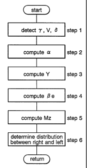
Now the control algorithm of the present invention is described in the
following in more detail with reference to the flow chart of Figure 1 and the
block diagram of Figure 2.
First of all, the steering wheel angle 6SW of the steering wheel is
transmitted to the front steering device 1 and the rear steering device 2, and
gives
rise to the front wheel steering angle 8F and the rear wheel steering angle
8R,
respectively. Various state variables of the vehicle (such as yaw rate 'y,
vehicle
speed V, and road wheel steering angles b) are also detected at this time
(step 1).
Then, the tire slip angles a of the front and rear wheels are obtained from
the following equations which are incorporated in tire slip angle computing
units
3 and 4 according to the steering angle information and the vehicle speed
information (step 2).
aF = (3e + (LF/V)y - 8F (front wheels) ... (10-1)
aR = (3e - (LR/V)y - 8R (rear wheels) ... (10-2)
where aF: front wheel slip angle,
aR: rear wheel slip angle,
(3e: hypothetical vehicle body slip angle,
SF: front wheel steering angle, and
8R: rear wheel steering angle.
The initial values of the tire slip angles a and the hypothetical vehicle body
slip
angle ~3e are assumed to be reset to value zero when the steering angles b and
the
CA 02254477 1998-11-19
_ $ _
yaw rate y are both zero.
The tire slip angles a are substituted into the following equation
(Equation (11)) for the dynamic model of the tires incorporated in cornering
force
computing units 5 and 6 to produce the cornering forces Y of the front and
rear
wheels (step 3).
Y = - (pCa - ~zC2a2/4pW),~1 - (~pW)2}lie
when ~a~ < 2W/C
Y = - l~W ~ 1 - (~w)2~'i2
when ~a~ > 2W/C ... (11)
where w: frictional coefficient between the road surface and the tires,
C: cornering power,
W: road contact load, and
X: fore-and-aft forces. w may consist of a value near 1, or a value
estimated by a known method.
C is a value obtained from a predetermined map given as a mathematical
function
of p, and W. W is a value compensated by the longitudinal and lateral
accelerations or a value obtained from a load sensor installed in a wheel
suspension system. X consists of a value estimated from the acceleration
(deceleration) or obtained from the brake fluid pressure or the engine output.
The
cornering force Y may be obtained from the equation of the dynamic model of
the tire (Equation (11)) while keeping the fore-and-aft force Z at zero, and
the
road contact load W at a fixed value. In this case, the accuracy in the
estimation
of the hypothetical vehicle body slip angle (3e may diminish, but the
stability of
the vehicle movement control would not be adversely affected to any
substantial
extent.
Based on the front wheel cornering force YF and the rear wheel cornering
force YR, a hypothetical vehicle body slip angle computing unit 7 produces a
hypothetical vehicle body slip angle (3e (step 4). In this case, the
hypothetical
vehicle body slip angle (3e is obtained by differentiating the hypothetical
vehicle
body slip angle, and then integrating it according to the following equation.
d(3~/dt = (YF + YR)/mV - ~y ... (12)
(3e f f [(YF + YR)/mVJ - y}dt ... (13)
By feeding back this hypothetical vehicle body slip angle (3e to the tire
CA 02254477 1998-11-19
_ g _
slip angle computing units 3 and 4, a practically adequate approximate value
of
the vehicle body slip angle can be obtained as a result. This is then
forwarded to a
sliding mode computing unit 8 which is characterized by the previously
mentioned Equation (8) to produce a yawing moment Mz which serves as the
basis for converging the vehicle body slip angle to zero (step 5). Based on
this
value, the fore-and-aft forces XR and XL of the right and left tires are
determined
in a manner similar to that mentioned in connection with the prior art (step
6),
and the vehicle 9 is controlled accordingly.
In this control algorithm, the frictional coefficient p, between the road
surface and the tire is not defined as a variable but as a fixed value, for
instance 1.
This, however, ensures the stability of the vehicle movement control. The
feasibility of this point is discussed in the following.
<Embodiment #1 - Example #1>
Figure 3 shows a case where the actual frictional coefficient p, is 1.0, the
assumed frictional coefficient p, is 1.0, and the steering wheel is turned by
60
degrees in each direction while the vehicle decelerates from the initial speed
of
120 km/h at the rate of - 0.4 G. In this case, the hypothetical vehicle body
slip
angle (3e agrees with the actual vehicle body slip angle [3, and the yaw rate
y and
the lateral acceleration YG follow the steering angle of the steering wheel
without any phase delay. In other words, a significant improvement can be made
in the vehicle movement under extreme conditions if the assumed frictional
coefficient p. and the actual frictional coefficient ~. agree with each other.
<Embodiment #1 - Example #2>
Figure 4 shows a case where the actual frictional coefficient ~, is 0.5, the
assumed frictional coefficient p, is 1.0, and the steering wheel is turned by
60
degrees in each direction while the vehicle decelerates from the initial speed
of
100 km/h at the rate of - 0.2 G. In this case, whereas the actual vehicle body
slip
angle (3 deviates from the hypothetical vehicle body slip angle (3e which
tends to
converge to zero, the yaw rate y demonstrates an adequate tracking property.
In
other words, if the assumed frictional coefficient p, is greater than the
actual
frictional coefficient ~., the stability of the vehicle movement can be
maintained
even though there is some phase delay in the lateral acceleration YG.
<Embodiment #1 - Example #3>
Figure 5 shows a case where the actual frictional coefficient p. is 1.0, the
assumed frictional coefficient ~. is 0.5, and the steering wheel is turned by
60
degrees in each direction while the vehicle decelerates from the initial speed
of
120 km/h at the rate of - 0.4 G. In this case, the hypothetical vehicle body
slip
CA 02254477 1998-11-19
- 10 -
angle (3e is opposite in phase to the actual vehicle body slip angle (3, and,
probably
for this reason, the yaw rate y is relatively low while the lateral
acceleration YG
overshoots. The response and stability are both inferior. This is probably due
to
the fact that when the assumed frictional coefficient p, is smaller than the
actual
frictional coefficient p,, only the tire which is lower in performance than
that of
the internal tire dynamic model is taken into consideration.
Thus, it can be seen from above that setting the assumed frictional
coefficient ~u higher than the actual frictional coefficient ~, would not
create any
significant problem for the stability and response of the vehicle. It can
therefore
be fixed at 1 for practical purposes, but it is also possible to change the
assumed
frictional coefficient p. by a number of steps, for instance, depending on the
fine,
raining and snowing conditions.
The above discussion was directed to the application of the present
invention to a four-wheel steering vehicle, but the present invention is
equally
applicable to vehicles which are steered only by the front wheels (second
embodiment). In this case, as illustrated in Figure 8, the terms related to
the rear
wheel steering angle disappear. In other words, the same treatment can be
extended simply by setting the rear wheel steering angle to zero (8R = 0).
<Embodiment #2 - Example #1>
Figure 6 shows a case where the actual frictional coefficient w is 1.0, the
assumed frictional coefficient p. is 1.0, and the steering wheel is turned by
60
degrees in each direction while the vehicle decelerates from the initial speed
of
120 km/h at the rate of - 0.4 G. In this case, the hypothetical vehicle body
slip
angle (3e agrees with the actual vehicle body slip angle (3, and the stability
and
response both improved.
<Embodiment #2 - Example #2>
Figure 7 shows a case where the actual frictional coefficient ~, is 0.5, the
assumed frictional coefficient p, is 1.0, and the steering wheel is turned by
60
degrees in each direction while the vehicle decelerates from the initial speed
of
100 km/h at the rate of - 0.2 G. In this case, the overall trends are
identical to
those of the four-wheel steering vehicle. In other words, if the assumed
frictional
coefficient ~, is greater than the actual frictional coefficient ~,, the
stability of the
vehicle movement can be maintained although there may be some phase delay in
the lateral acceleration YG.
Equations (12) and (13) given above can give the vehicle slip angle at
high precision if the fore-and-aft speed VX of the vehicle body is
sufficiently
greater than the vehicle body slip angle VY, and the changes in the fore-and-
aft
CA 02254477 1998-11-19
- 11 -
speed VX are relatively small, but under extreme conditions when such a
relation
does not hold, the following more precise equations may be used.
dVyldt = (YF + YR)/m - yVX ... (14)
Vy = f{(I'F + YR)/m - YVX}dt ... (15)
[3e = tari 1(VY/VX) ... (16)
In this case, because the vehicle speed is typically measured by using a
vehicle
sensor for detecting the rotational speed of the wheel, the output of such a
vehicle
speed sensor may be used as the fore-and-aft speed VX of the vehicle body. A
higher precision can be achieved if the vehicle speed V in Equations (12) and
(13) are replaced by the fore-and-aft speed VX of the vehicle body.
Figure 10 is a block diagram of a control system for a four-wheel
steering vehicle given as a third embodiment of the present invention which
uses
these equations for more precisely estimating the vehicle body slip angle. It
should be noted that the hypothetical vehicle body slip angle computing unit T
is
somewhat different from the hypothetical vehicle body slip angle computing
unit
7 of the first embodiment illustrated in Figure 2. The properties of the
vehicle
motion control in the third embodiment of the present invention are compared
with those demonstrated when such a control process is absent by simulation.
<Example for Comparison #2 for Embodiment #3>
Figure 11 shows a case where the actual frictional coefficient p. is 1.0,
and the steering wheel is turned by 60 degrees in each direction while the
vehicle
decelerates from the initial speed of 120 km/h at the rate of - 0.4 G without
carrying out the control process of the present invention. In this case, the
vehicle
body went into a spin, and the vehicle behavior was highly unstable.
<Embodiment #3 - Example #1>
Figure 12 shows a case where the actual frictional coefficient ~u is 1.0, the
assumed frictional coefficient p, is 1.0, and the steering wheel is turned by
60
3o degrees in each direction while the vehicle decelerates from the initial
speed of
120 km/h at the rate of - 0.4 G. In this case, the hypothetical vehicle body
slip
angle (3e agrees with the actual vehicle body slip angle (3, and the yaw rate
'y and
the lateral acceleration YG follow the steering angle of the steering wheel
without any phase delay. In other words, a significant improvement can be made
in the vehicle movement under extreme conditions if the assumed frictional
coefficient p. and the actual frictional coefficient ~. agree with each other.
<Embodiment #3 - Example #2>
CA 02254477 1998-11-19
- 12 -
Figure 13 shows a case where the actual frictional coefficient p, is 1.0, the
assumed frictional coefficient p, is 0.2, and the steering wheel is turned by
60
degrees in each direction while the vehicle decelerates from the initial speed
of
120 km/h at the rate of - 0.4 G. In this case, even though the assumed
frictional
coefficient p, is lower than the actual frictional coefficient p,, besides
from a slight
deviation of the actual vehicle body slip angle (3 from the hypothetical
vehicle
body slip angle (3e, the stability of the vehicle motion is not impaired.
<Example for Comparison #2 for Embodiment #3>
Figure 14 shows a case where the actual frictional coefficient p. is 0.2,
and the steering wheel is turned by 60 degrees in each direction while the
vehicle
decelerates from the initial speed of 120 km/h at the rate of - 0.1 G without
carrying out the control process of the present invention. In this case also,
the
vehicle body went into a spin, and the vehicle behavior was highly unstable.
<Embodiment #3 - Example #3>
Figure 15 shows a case where the actual frictional coefficient p, is 0.2, the
assumed frictional coefficient ~, is 0.2, and the steering wheel is turned by
60
degrees in each direction while the vehicle decelerates from the initial speed
of
100 km/h at the rate of - 0.1 G. In this case, the hypothetical vehicle body
slip
angle (3e agrees with the actual vehicle body slip angle (3, and the yaw rate
y and
the lateral acceleration YG follow the steering angle of the steering wheel
without any phase delay. In other words, a significant improvement can be made
in the vehicle movement under extreme conditions if the assumed frictional
coefficient p, and the actual frictional coefficient p, agree with each other.
<Embodiment #3 - Example #4>
Figure 16 shows a case where the actual frictional coefficient p. is 0.2, the
assumed frictional coefficient p, is 1.0, and the steering wheel is turned by
60
degrees in each direction while the vehicle decelerates from the initial speed
of
100 km/h at the rate of - 0.1 G. In this case, because the assumed frictional
coefficient p, is higher than the actual frictional coefficient p, contrary to
the case
of Embodiment #2-2, the deviation of the actual vehicle body slip angle (3
from
the hypothetical vehicle body slip angle (3e is even smaller, and a fairly
high level
of stability can be attained.
As described above, according to the present invention, a vehicle body
slip angle can be determined both accurately and promptly for application to a
vehicle movement control, and although the frictional coefficient between the
tires and the road surface which is an essential data for the tire model for
the
vehicle movement control, an arbitrarily assumed frictional coefficient is
found to
CA 02254477 1998-11-19
- 13 -
be adequate for practical purpose. In particular, when the assumed frictional
coefficient is higher than the actual frictional coefficient, favorable
control results
were obtained. It was however discovered that the knowledge of the actual
frictional coefficient highly beneficial for even more precise and stable
control
results.
Figures 17 and 18 illustrate a control arrangement based on such a
consideration, and the control system is incorporated with means for
estimating
the frictional coefficient between the tires and the road surface. Now the
control
algorithm of this aspect of the present invention is described in the
following in
l0 more detail with reference to the flow chart of Figure 17 and the block
diagram of
Figure 18.
First of all, the steering wheel angle 6SW of the steering wheel is
transmitted to the front steering device 1 and the rear steering device 2, and
gives
rise to the front wheel steering angle 8F and the rear wheel steering angle
8R,
respectively. Various state variables of the vehicle (such as yaw rate y,
vehicle
speed V, road wheel steering angles b, and lateral acceleration GY) are also
detected at this time (step 1).
Then, the tire slip angles a of the front and rear wheels are obtained from
Equations (10-1) and (10-2) which are mentioned earlier, and incorporated in
tire
slip angle computing units 3 and 4 according to the steering angle information
b
and the vehicle speed information V (step 2) similarly as in the first
embodiment.
The tire slip angles a are substituted into Equation (11) for the dynamic
model of the tires incorporated in cornering force computing units 5 and 6 to
produce the cornering forces Y of the front and rear wheels (step 3).
Based on the front wheel cornering force YF and the rear wheel cornering
force YR, a hypothetical vehicle body slip angle computing unit 7 produces a
hypothetical vehicle body slip angle (3e (step 4). In this case, the
hypothetical
vehicle body slip angle (3e is obtained by differentiating the hypothetical
vehicle
body slip angle, and then integrating it according to Equations (12) and (13)
which are also given earlier.
By feeding back this hypothetical vehicle body slip angle (3e to the tire
slip angle computing units 3 and 4, a practically adequate approximate value
of
the vehicle body slip angle can be obtained as a result. This is then
forwarded to a
sliding mode computing unit 8 which is characterized by Equation (1) mentioned
in connection with the prior art to produce a yawing moment Mz which serves as
the basis for converging the vehicle body slip angle to zero (step 5). Based
on this
value, the fore-and-aft forces XR and XL of the right and left tires are
determined
CA 02254477 1998-11-19
- 14 -
(step 6), and the vehicle 9 is controlled accordingly.
The control stability would not be impaired for any practical purpose
even when the frictional coefficient ~, between the tire and the road surface
which
is used in the tire dynamic model (Equation (11)) incorporated in cornering
force
computing units 5 and 6 is set at an appropriate fixed value near 1, but it
was
confirmed that a higher precision in the value of ~, is beneficial in
improving the
response. Therefore, according to this aspect of the present invention, the
value of
~, is estimated from the lateral acceleration GY, the vehicle speed V and the
yaw
rate y which are relatively easy to directly detect, and this value of p, is
used in
l0 the processing of Step 3. The operation of a ~, estimating unit 10 for
estimating
the value of ~, is now described in the following with reference to Figures 3
and
5.
The computation of the hypothetical vehicle body slip angle (3e using the
cornering forces Y computed from the tire dynamic model (Equation (11)) is
continually executed in the processing of step 4. The time point when the
absolute value of (3e falls below a certain value near zero is determined
(step 11).
When the absolute value of die falls below this value near zero, the detected
values of the lateral acceleration GY, yaw rate y, and the vehicle speed are
supplied to an integrator 11, and an estimated vehicle body slip angle (3D is
obtained from the following equation (step 12).
(3D = J ~ (Gy/V) - y}dt, T = Jdt ... (17)
When the absolute value of (3e falls below this value near zero, the
computed value of the estimated vehicle body slip angle (3D is reset, and the
integration is started in such a manner that the computation of (3D takes
place only
for a prescribed time period (such as T = 2 - 3 seconds) when the absolute
value
of the change rate of the steering angle is less than a prescribed value. By
repeating this, it is possible to avoid accumulating integration errors.
The thus obtained estimated vehicle body slip angle (3D is supplied to an
estimated vehicle body slip angle computing unit 12, and the estimated tire
slip
angle ae is obtained for each of the front and rear wheels from the following
equations (step 13).
aeF - ~D + (L'F~~ - SF ... 1g-1
aeR - ND + (L'R~)Y - SR ... (18-2)
CA 02254477 1998-11-19
- 15 -
Meanwhile, only when the estimated vehicle body slip angle (3D is being
computed, the lateral acceleration GY and yaw rate y corresponding to this
time
period are supplied to an estimated cornering force computing unit 13, and the
estimated cornering force Ye is obtained from the equations of motions as a
reverse computation for each of the front and rear wheels (step 14).
YeF = 1/2L{m-LR~GY + I(dy/dt)} ~ mF GyF ... (19-1)
YeR = 1/2L{m~LF~GY + I(dy/dt)} ~ mR~GYR ... (19-2)
i0 where mF: mass of the front axle
mR: mass of the rear axle
Gyg: lateral acceleration at the front axle
GyR: lateral acceleration at the rear axle
L: wheel base (LR + LL)
15 The thus obtained estimated cornering forces YeF and YeR and the
estimated tire slip angles aeF and aeR are supplied to a p. computing unit 16.
Data
on the relationship between the estimated cornering forces Ye and the
estimated
tire slip angles ae is built up (step 15). Once it is judged that a sufficient
amount
of data has been built up (for instance the data includes the case of slip
angles of
20 five degrees or more), the estimated tire slip angles ae are supplied to a
tire
property model 14 of the vehicle in which the experimentally obtained
relationship between the tire slip angle a, the cornering force Y and the
frictional
coefficient p. between the tire and the road surface is stored in advance in
the
form of a map. The hypothetical cornering force Yd is then obtained from each
of
25 the right and left wheels while varying ~, from 0 to 1.2 (step 16).
The hypothetical cornering forces YdF and YdR obtained from the data on
this relationship, and the estimated cornering forces YeF and YeR are supplied
to a
comparator 15 to obtain the value of p. which minimizes the average root-mean-
squares of the deviations (step 17), and the computation of step 3 is carried
by
30 using this optimized value of ~. (step 18).
Such a processing procedure is executed in a sequential manner (at an
appropriate frequency) when the vehicle is traveling without any acceleration
or
deceleration so that the vehicle movement control may be carried out on a real
time basis by taking into account the current changes in the condition of the
road
35 surface.
Equations (6) and (7) given above produce the vehicle body slip angle at
a high precision if the fore-and-aft speed VX of the vehicle body is
sufficiently
CA 02254477 1998-11-19
- 16 -
greater than the vehicle body slip angle VY, and the changes in the fore-and-
aft
speed Vx are relatively small, but under extreme conditions when such a
relation
does not hold, Equations (14) to (16) may be used instead of Equations (12)
and
(13).
Figure 21 is a block diagram of a control system for a four-wheel
steering vehicle given as a fifth embodiment of the present invention which
uses
these equations for more precisely estimating the vehicle body slip angle. It
should be noted that the hypothetical vehicle body slip angle computing unit T
in
this case is different from the hypothetical vehicle body slip angle computing
unit
7 of the fourth embodiment illustrated in Figure 18.
The above discussion was directed to the application of the present
invention to a four-wheel steering vehicle, but the present invention is
equally
applicable to vehicles which are steered only by the front wheels as can be
readily appreciated from the comparison of the first and second embodiments.
Thus, according to the present invention, in the vehicle movement
control, the vehicle movement can be controlled with an adequate response and
stability for practical purposes even without accurately determining the
frictional
coefficient between the road surface and the tire, and the knowledge of the
frictional coefficient based on an estimation from the dynamic behavior of the
vehicle can even further improve the performance of the control process.
Therefore, the overall structure of the system can be simplified, and the
manufacturing cost can be reduced. Therefore, a significant progress can be
made
in providing a vehicle operation assist system of a high performance.
Although the present invention has been described in terms of preferred
embodiments thereof, it is obvious to a person skilled in the art that various
alterations and modifications are possible without departing from the scope of
the
present invention which is set forth in the appended claims.