Note: Descriptions are shown in the official language in which they were submitted.
CA 022~4487 l998-ll-l9
OPTICAL FIBER AMPLIFIER
BACKGROUND OF THE INVENTION
1. Field of the Invention
The present invention relates to an optical fiber amplifier, and more
particularly, to an optical fiber amplifier which obtains gain-flattened amplification
characteristics by cascading optical fibers doped with different materials.
2. Description of the Related Art
Wavelength division multiplexing (WDM) transmission has emerged in the
latter half of the 1990s as a means for increasing transmission capacity and
10 effficiency by multiplexing and transmitting optical signals of different wavelengths.
Thus, an optical fiber amplifier appropriate for the WDM transmission is required.
However, an erbium-doped fiber (EDF) amplifier currently and widely in use showsdifferent amplification degrees and noise figures for different wavelengths.
FIG. 1 is a block diagram of a conventional EDF amplifier, comprising a first
isolator 100, a pumping laser source 102, a wavelength selective coupler (WSC)
104, an EDF 106, and a second isolator 108.
Their operations will now be described. First, the pumping laser source 102
generates pumping light of a central wavelength of 980nm. The WSC 104 couples
the pumping light to signal light of a 1500nm band wavelength entering via its
input port. The EDF 106 amplifies the signal light according to the pumping light
incident from the WSC 104. That is, the pumping light excites erbium ions of
ground-state in the EDF, and the signal light is amplified by stimulated emission of
the excited erbium. The amplified optical signal is output via the second isolator
108. The first and second isolators 100 and 106 prevent the signal light from
being reflected by elements such as input and output connectors 110 and 112 and
reentering the EDF.
However, such a conventional optical fiber amplifier has a problem in that
signal light of different wavelengths does not provide flattened gains. That is,when input signal channels 1, 2, 3 and 4 of equal powers are incident, the
.
CA 022~4487 l998-ll-l9
conventional optical fiber amplifier outputs signal channels having different powers
at different wavelengths.
In order to solve the above problem, the prior art uses filters or changes the
configuration of EDFs. However, use of the filters increases costs and increasesthe size of the conventional optical fiber amplifier. The above-described methods
result in a reduction in gain since they flatten output powers on the basis of the
minimum power among the output powers at different wavelengths. The use of
EDFs doped with a material having a different basic composition, such as fluoride,
enlarges a gain flattening band, but reduces gains and shows characteristics
10 unstable to environments.
SUMMARY OF THE INVENTION
To solve the above problems, it is an object of the present invention to
provide an optical fiber amplifier having a flattened gain by cascading EDFs to
which different materials are added.
Accordingly, to achieve the above object, there is provided an optical fiber
amplifier comprising: a first optical fiber doped with erbium and phosphorous, for
amplifying signal light excited by the erbium; a second optical fiber connected to
one end of the first optical fiber, doped with erbium and aluminum, and having again spectrum slope opposite to the first optical fiber according to population
inversion of the erbium, for amplifying signal light output by the first optical fiber; a
pumping laser source connected to the other end of the first optical fiber, for
exciting the erbium of the first and second optical fibers; and a light coupler for
coupling pumping light from the pumping laser source to the signal light and
outputting the resultant light to the first optical fiber.
BRIEF DESCRIPTION OF THE DRAWINGS
The above object and advantage of the present invention will become more
apparent by describing in detail a preferred embodiment thereof with reference to
the attached drawings in which:
FIG. 1 is a block diagram of a conventional optical fiber amplifier;
FIG. 2 is a block diagram of an optical fiber amplifier according to the
present invention;
CA 022~4487 l998-ll-l9
FIGS. 3A and 3B show gain spectrums according to the population
inversion distributions of the first and second EDFs of FIG. 2;
FIG. 4 is a graph showing gains and noise figures vs. wavelengths when
four channel signal lights are multiplexed and input to the optical fiber amplifier of
FIG. 2;
FIG. 5 is a graph showing gains and noise figures measured as signal light
powers for different channels change while pumping light powers are kept
constant;
FIG. 6 is a graph showing gains and noise figures measured as pumping
light powers are changed while signal light powers for four channels are kept
constant;
FIG. 7 is a block diagram of an optical fiber amplifier having a bidirectional
pumping laser source, according to the present invention;
FIG. 8 is a graph showing gains and noise figures vs. wavelengths when
four channel signal lights are incident upon the optical fiber amplifier of FIG. 7;
FIG. 9 is a graph showing gains and noise figures measured as signal light
powers for different channels are changed while pumping light powers are kept
constant; and
FIG. 10 is a graph showing gains and noise figures measured as pumping
light powers are changed while signal light powers for four channels are kept
constant.
DESCRIPTION OF THE PREFERRED EMBODIMENTS
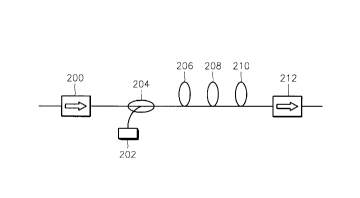
Referring to FIG. 2, an optical fiber amplifier includes a first isolator 200, apumping laser source 202, a wavelength selective coupler (WSC) 204 connected
to the first isolator 200 and the pumping laser source 202, a buffer EDF 206, first
and second EDFs 208 and 210, and a second isolator 212.
The first EDF 208 is an optical fiber doped with erbium (Er) and
phosphorous (P), or an optical fiber doped with Er, aluminum (Al), and P.
The buffer EDF 206 and the second EDF 210 are optical fibers doped with
Er and Al. The buffer EDF 206 is not necessarily the optical fiber doped with Erand Al. It is preferable that the buffer EDF 206 is an optical fiber which can
reduce splice loss caused by the mode field diameter difference between the WSC
. .
CA 022~4487 l998-ll-l9
204 and the first EDF 208. The buffer EDF 206 is short so as not to affect the
gain characteristics of the entire amplifier. The concentrations of Er and Al of the
buffer EDF 206 may be equal to or different from those of the second EDF 210.
The buffer EDF 206 may not be used since it reduces the splice loss but has no
effect on the gain flatness of the optical fiber amplifier.
Their operations will now be described. First, several channel signal lights
are incident upon the WSC 204 via the first isolator 200 which prevents amplified
spontaneous emission from each EDF from flowing backward and being reflected.
The incident signal lights are coupled to a pumping laser from the pumping laser10 source 202, such as a laser diode, for supplying power having a central
wavelength of 980nm and necessary for amplification, by the WSC 204. The
signal lights are amplified by the first and second EDFs 208 and 210.
The first EDF 208 amplifies more lights of a relatively short wavelength than
other signal lights of wavelengths between 1540nm and 1560nm. The second
EDF 210 amplifies more lights of a relatively long wavelength than other signal
lights of wavelengths between 1540nm and 1560nm. This results from the gain
spectrum characteristics depending on the wavelengths of the first and second
EDFs 208 and 210.
FIG. 3A shows a gain spectrum depending on the population inversion
distribution of the first EDF 208. FIG. 3B shows a gain spectrum depending on
the population inversion distribution of the second EDF 210. Each of these gain
spectrums is shown as the ratio of population inversion increases in units of 0.1
between 0 and 1. In FIGS. 3A and 3B, the gain characteristics of the EDFs at
different wavelengths vary with the ratio of population inversion. That is, in FIG.
3A, the gain of the first EDF 208 becomes lower with an increase in wavelength
between 1540nm and 1560nm when the ratio of population inversion is 0.6 or
larger. When the ratio of population inversion is 0.5 or smaller, the gain thereof
becomes larger with an increase in wavelength. However, where the gain
increases as the wavelength becomes longer, the first EDF 208 is not desirable as
an amplifier since its gain per unit length is 0.5dB/m or less, i.e., its amplification
level is low. The first EDF 208 is thus appropriate when the ratio of populationinversion is 0.6 or larger. In this case, the amplification gain of the first EDF 208
becomes higher in short wavelengths rather than long ones.
CA 022~4487 l998-ll-l9
In FIG. 3B, the gain of the second EDF 210 becomes lower as the
wavelength becomes longer, in the same wavelength range as in FIG. 3A, when
the ratio of population inversion is 0.8 or larger. When the ratio of populationinversion is 0.7 or less, the gain becomes higher as the wavelength becomes
longer. Thus, in order to increase the gain at long wavelengths relatively reduced
by the first EDF 208, it is preferable that the ratio of population inversion of the
second EDF 210 is 0.7 or less.
If the first and second EDFs 208 and 210 are both used between 0.6 and
0.7 of ratios of population inversion, pumping laser power becomes higher and
signal light power becomes lower in the first EDF 208, causing the ratio of
population inversion to be larger. On the other hand, in the second EDF 210, thepumping light power becomes lower and the signal light power becomes higher,
thus causing a decrease in the ratio of population inversion. An optical fiber
ampliher having an entirely flat gain can be thus obtained.
After being amplified, the signal light is output via the second isolator 212
for preventing backward flow of forward spontaneous emission.
FIG. 4 is a graph showing gain and noise figures vs. wavelengths when four
channel signal lights respectively having wavelengths of 1542nm, 1548nm,
1554nm, and 1560nm are input to the optical fiber amplifier of FIG. 2. Variations
in the gain and noise figure are flattened within iO.5dB at wavelengths between
1542nm and 1560nm. Reference numerals 401 and 402 represent noise figures
and gains, respectively.
FIG. 5 is a graph showing gains and noise figures measured as the powers
of the above-described four-channel signal lights are changed from -20dBm to
-11dBm while pumping light powers are kept constant. As shown in FIG. 5,
variations in the gain and noise figure are flattened within iO.5dB. Reference
numerals 501 and 502 represent the noise figure and the gain, respectively.
FIG. 6 is a graph showing gains and noise figures measured as pumping
light powers are changed from 70mW to 130mW while the four channel signal light
powers are kept constant. As shown in FIG. 6, variations in the gain and noise
figure are flattened within iO.5dB. Reference numerals 601 and 602 represent thenoise figure and the gain, respectively.
CA 022~4487 l998-ll-l9
FIG. 7 is a block diagram of an optical fiber amplifier configured by adding a
second pumping laser source 701 and a second WSC 702 to the optical fiber
amplifier of FIG. 2 to achieve bidirectional pumping. The remaining elements arethe same as those of FIG. 2.
FIG. 8 is a graph showing gains and noise figures vs. wavelengths when
four channel signal lights having wavelengths of 1542nm, 1548nm, 1554nm and
1560nm are incident upon the optical fiber amplifier of FIG. 7. As shown in FIG.8, variations in the gain and noise figure are flattened within iO.5dB at
wavelengths between 1542nm and 1560nm. Reference numerals 801 and 802
represent noise figures and gains, respectively.
FIG. 9 is a graph showing gains and noise figures measured as the powers
of the above-described four-channel signal lights are changed from -20dBm to
-11dBm while pumping light powers are kept constant. As shown in FIG. 9,
variations in the gain and noise figure are flattened within iO.5dB. Reference
numerals 901 and 902 represent the noise figure and the gain, respectively.
FIG. 10 is a graph showing gains and noise figures measured as pumping
light powers are changed from 140mW to 260mW while the four channel signal
light powers are kept constant. As shown in FIG. 10, variations in the gain and
noise figure are flattened within iO.5dB. Reference numerals 1001 and 1002
represent the noise figure and the gain, respectively.
When passive elements such as hlters are used, the gain flatness is
changed with the signal light power or the pumping light power. However, the
present invention uses two types of EDFs having different gain spectrums, such
that the gain spectrum of each of the EDFs actively varies with the input signallight power or pumping light power. Thus, an entirely flat gain can be maintained.