Note: Descriptions are shown in the official language in which they were submitted.
CA 02254656 1998-11-23
EXISTING PIPE CUT-OFF METHOD, EXISTING PIPE SLITTING
METHOD, PIPING STRUCTURE, AND VALVE INSERTION METHOD FOR
INSERTING A VALVE IN A LINE WITHOUT STOPPING PASSAGE OF
WATER OR FLUID
Background of the invention
Field of the invention
The present invention relates to an existing pipe cut-
off method, and a valve insertion method for inserting a
valve in a line without stopping passage of water or
fluid, etc.
Description of prior arts
Conventionally, a valve insertion method for inserting
a valve in a line without stopping passage of water, by
which an existing pipe is cut off without stopping passage
of water and a valve is inserted into the cut-off portion
of the existing pipe in a line including the existing
pipe, has been already publicly known.
FIG.72 shows a sketch of a conventional method
disclosed in Japanese Laid-Open~Patent Publication Nos.
44167 of 1980, 83690 of 1981, 120886 of 1981, and 47089 of
1982.
-1-
CA 02254656 1998-11-23
The method illustrated in the drawing is such that
cutting equipment 500 is fixed at an existing pipe 1, the
cutting equipment 500 and existing pipe 1 are enclosed and
sealed up by a seal-up housing 501, and the left and right
blades 502 are rotated along the cutting equipment 500 in
order to cut off the existing pipe 1. Thereafter, a valve
is inserted into a line 1A instead of a cut-off section 10
of the existing pipe 1 by opening and closing an operation
sluice valve 503. In the prior art, since the cutting
equipment 500 is accommodated in the seal-up housing 501,
the seal-up housing 501 is made large-scaled to
resultantly expand the digging area, etc.
FIG.73 shows a sketch of a prior method disclosed in
United States Patent No. 5,611,365 and International Laid-
Open WO 97/31207.
With the method illustrated in the drawing, an existing
pipe 1 is enclosed and sealed up by a seal-up housing 600,
a cutting tool 602 is fixed at and attached to the tip end
of a gate valve 601 installed at the seal-up housing 600,
and the gate valve 601 is turned together with the seal-up
housing 600, wherein an existing pipe 1 is cut off by the
cutting tool 602. According to the prior arts, since the
cutting tool 602 is turned by rotations of the seal-up
-2-
CA 02254656 1998-11-23
housing 600, it is not necessary that the seal-up
mechanism for turning the cutting tool 602 is provided in
a seal-up housing 600. Therefore, the seal-up housing 600
can be small-sized.
However, with such conventional cut-off methods, a
chip-like cutter 602 bites an existing pipe 1. Therefore,
in a housing of cutting into an existing pipe 1 made of
cast iron or steel, the seal-up housing 600 must be turned
many times, wherein it takes much time to cut off.
Furthermore, there is a fear that rubber packing to seal
between the seal-up housing 600 and existing pipe 1 is
damaged.
Fig.74 shows a sketch of a conventional cut-off method
disclosed in United States Patent Nos. 3,650,547,
3,703,906, and 3,735,775.
With the prior art shown in the drawing, an existing
pipe 1 is enclosed and sealed up by a seal-up housing 700,
and after a cutting wheel 701 attached to the seal-up
housing 700 is caused to bite the existing pipe 1 by a
lead screw 702, the cutting wheel 701 is turned together
with the seal-up housing 700, whereby the existing tube 1
is cut off.
-3-
CA 02254656 1998-11-23
With the cutting method, since the cutting wheel 701
has a smooth outer circumferential part, it is impossible
to cut off an existing pipe 1 made of cast iron and steel.
FIG.75(a) and FIG.75(b) show views of a conventional
method for inserting a valve in a line without stopping
passage of water, which is disclosed in United States
Patent No. 3,948,282.
With the conventional method shown in these drawings,
an existing pipe 1 shown in FIG.75(a) is enclosed and
sealed up by a seal-up housing 800. Subsequently, an
operation sluice valve 801 is attached to the seal-up
housing 800. Thereafter, a circular hole 803 is drilled by
using a hole saw 802 in compliance with an already known
method. After the drilling is completed " as shown in
FIG.75(b), a valve body 804 which is fitted into the
drilled circular hole 803 is inserted therein.
With the conventional valve inserting method, since the
hole 803 which has roughly the same diameter as the inner
diameter of the existing pipe 1 is provided, the seal-up
housing 800 shown in FIG.75(a) is made longer in the axial
direction S and is made large-sized.
Furthermore, with the conventional inserting method,
since hydraulic pressure is given to the valve body 804
-4-
CA 02254656 1998-11-23
shown in FIG.75(b) with respect to a large area equivalent
to the circular hole, the diameter of the valve rod 806 is
unavoidably made large.
Still furthermore, with the conventional inserting
method, the circumferential edge 805 of the hole 803 at
the existing pipe 1 is made thin, and pressure resulting
from the valve body 804 is applied to the circumferential
edge 805, wherein the existing pipe 1 is liable to be
broken.
FIG.76(a) and FIG.76(b) show the outline of a
conventional valve insertion method for inserting a valve
in a line without stopping passage of water, which was
disclosed in United States Patent No. 4,156,598.
In the prior art shown in these drawings, the existing
pipe 1 in FIG.76(a) is enclosed and sealed up by an seal-
up housing 800. At this time, a hole saw 802 and a valve
body 804 are accommodated in advance in the seal-up
housing 800. Thereafter, a circular hole is drilled at the
existing pipe 1 by the hole saw 802. After the drilling is
completed, the seal-up housing 800 is turned as shown by
the arrow 850 in FIG.76(a). After that, a valve body 804
is inserted into the circular hole 803 in FIG.76(b).
-5-
CA 02254656 1998-11-23
FIG.77 shows the outline of a conventional valve
insertion method for inserting a valve in a line without
stopping passage of water, which was disclosed in United
States Patent No. 1,989,768.
In the prior art shown in this drawing, the existing
pipe 1 in FIG.77 is enclosed and sealed up by a seal-up
housing 501. At this time, cutting equipment 500 and a
sluice valve 510 are accommodated in advance in the seal-
up housing 501. After the cutting equipment 500 having a
blade 502 cuts off and removes the existing pipe 1, the
sluice valve is inserted instead of the cutting equipment
500.
The prior arts shown in FIG.76(a), 76(b), and FIG.77
are able to quickly insert a valve after the cutting is
completed. But with the prior arts shown in FIG.76(a),
76(b), and FIG.77, since it is necessary to accommodate a
hole saw 802 or cutting equipment 500, the size of which
is equivalent to that of the valves 804 and 510 to be
inserted, in the seal-up housing 800 or 501, the seal-up
housings 800 and 501 are obliged to be large-scaled.
SUMMARY OF THE INVENTION
-6-
CA 02254656 2003-12-19
The present invention has been developed to solve the
problems inherent to the prior arts, and it is therefore a
major object of the invention to provide an existing pipe
cut-off method by which the existing pipe made of cast iron
or steel can be cut off without causing its seal-up housing
to turn many times.
It is another object of the invention to provide a method
for inserting a valve in a line without stopping passage of
water, in which the abovementioned method is employed.
It is still another object of the invention to provide a
piping structure in which an existing pipe is scarcely
damaged, an existing pipe slitting method by which the
existing pipe can be slit to such a shape as the existing
pipe is scarcely damaged, and a method for inserting a valve
in a line without stopping passage of fluid.
Accordingly, the present invention provides a method for
inserting a valve in a line without stopping passage of
fluid, comprising the steps of: accommodating a cutting tool,
which is rotatably supported on an axial line established
roughly in a cross direction of an existing pipe and is
provided with a plurality of blades on a tip end face and
outer circumferential surface of a columnar portion thereof,
in a seal-up housing in a state where the cutting tool is
attached to said seal-up housing while enclosing, in an
airtight state, a part of said existing pipe by said seal-up
housing which is divided into plural sections in the
circumferential direction of the existing pipe; feeding said
cutting tool roughly in the cross direction of said existing
pipe in a state of performing a slitting motion to slit said
existing pipe by rotations of said cutting tool by causing
said cutting tool to rotate on said axial line by power of a
prime mover, wherein a slit groove cut open in a range of
approximately 180 degrees in the circumferential direction of
CA 02254656 2003-12-19
said existing pipe is formed by slitting said existing pipe
by said cutting tool in a range of approximately 180 degrees
in the circumferential direction thereof by causing said
cutting tool to perform a feed motion with said cutting tool
turned in said circumferential direction by causing at least
a part of said seal-up housing to turn in said
circumferential direction of said existing pipe; and
disposing a sluice valve having a sluice valve body for
stopping said existing pipe, which invades from said slit
groove into said existing pipe, clogs said slit groove and is
pressure-fitted to the inner circumferential surface of said
existing pipe, at a point corresponding to said slit groove.
The present invention also provides a piping structure
comprising: an existing pipe having a slit groove notched
and cut open so as to cover a range of approximately 180
degrees in a circumferential direction of an existing pipe; a
seal-up housing which is divided into plural sections in the
circumferential direction of said existing pipe and seals up
said existing pipe in an airtight state; a sluice valve body
which has rubber packing being in contact with both an inner
circumferential surface of said existing pipe and a slit
surface forming said slit groove at said existing pipe in a
closed state, moves roughly in a cross direction of said
existing pipe in said seal-up housing, invades from said slit
groove into said existing pipe, and stops passage of fluid in
said existing pipe by said rubber packing being pressure-
fitted to said inner circumferential surface and slit
surface; and a valve rod by which said valve body is caused
to move roughly in the cross direction.
Lastly, the present invention provides apparatus for
inserting a valve in a line without stopping passage of
fluid, comprising a cutting tool which is provided with a
plurality of blades on a tip end face and outer
-7a-
CA 02254656 2003-12-19
circumferential surface of a columnar portion thereof, the
cutting tool being accommodated in a seal-up housing, the
housing being divided into plural sections in a
circumferential direction of an existing pipe and having
means for enclosing a part of said existing pipe in an
airtight state; and further comprising means for feeding said
cutting tool roughly in a cross direction of said existing
pipe; and a prime mover and means for causing said cutting
tool to rotate on an axial line established roughly in the
cross direction of said existing pipe in order to cause said
cutting tool to perform a slitting motion to slit said
existing pipe by rotations of said cutting tool; and means
for causing at least a part of said seal-up housing to turn
in a circumferential direction of said existing pipe in order
to cause said cutting tool to perform a feed motion with said
cutting tool turned in said circumferential direction in
order to cut open a slit groove in a range of approximately
180 degrees in the circumferential direction of said existing
pipe; the apparatus further comprising a sluice valve having
a sluice valve body for stopping said passage of fluid and
means for invading said sluice valve body from said slit
groove into said pipe in order to clog said slit groove and
to pressure-fit it to the inner circumferential surface of
said existing pipe at a point corresponding to said slit
groove.
In order to achieve the abovementioned main object, in a
cut-off method according to the invention, a cutting tool,
which is fixed at a rotatably supported cutter shaft and is
provided with a plurality of blades, is accommodated in a
seal-up housing in a state where the cutting tool is attached
to the abovementioned seal-up housing while enclosing, in an
airtight state, a part of
-7b-
CA 02254656 1998-11-23
an existing pipe by the abovementioned seal-up housing which
is divided into plural sections in the circumferential
direction of the existing pipe.
Subsequently, the abovementioned cutting tool is fed
roughly in the cross direction of the abovementioned existing
pipe in a state of performing a slitting motion to slit the
abovementioned existing pipe by rotations of the
abovementioned cutting tool by causing the abovementioned
cutting tool to rotate on the abovementioned cutter shaft by
power of a prime mover, wherein the abovementioned cutting tool
is caused to perform a feed motion with the abovementioned
cutting tool turned in the abovementioned circumferential
direction by causing at least a part of the abovementioned
seal-up housing to turn in the abovementioned circumferential
direction of the abovementioned existing pipe, and the
abovementioned existing pipe is cut off by the abovementioned
cutting tool.
According to the invention, since the existing pipe is slit
by rotating the cutting tool on its cutter shaft, any existing
pipe made of cast iron or steel is able to be easily cut off
by turning the seal-up housing one to three times.
Therefore, the cut-off time can be shortened, and
_8_
CA 02254656 1998-11-23
there is no fear that rubber packing secured at the
rotating and sliding portion is damaged.
In the invention, "existing pipe" means a pipe through
which fluid such as water flows and is generally buried
under the ground.
"Seal-up" does not mean "completely sealed" but means
such a state where work can be carried out without
stopping passage of water or fluid. Therefore, "seal-up
housing" means a housing which has such a pressure
resisting capacity, by which it can withstand the pressure
of fluid flowing through the existing pipe, and has a
sealing capacity to some degree.
Furthermore, "enclosed and sealed up in an airtight
state" means such a sealed up state where work such as
inserting a valve in a line after cut-off or slitting is
not hindered, for example, wherein a water discharge port
is provided at the seal-up housing and is made open during
slitting of an existing pipe, and cutting chips may be
discharged through the discharge port together with water.
Since a "cutting tool" used in the present cut-off
method has a plurality of blades, the corresponding
cutting tool does not include a cutting chip and a cutter
wheel having a single continuous blade. As the "cutting
-9-
CA 02254656 1998-11-23
tool" used in the cut-off method, a columnar cutting tool
having a plurality of blades on its tip end and its outer
circumferential surface may be used in addition to a
diamond wheel and a metal slitting saw, etc.
Here in the specification, "pillar shape" means a
conical trapezoidal shape in addition to a columnar shape,
and includes such a shape, in which a conical shape is
added to a column, and a conical shape. Furthermore, it
may be of a short-pillar shape in comparison with the
outer diameter of a cutting tool.
Furthermore, in a housing of slitting an existing pipe
having mortar lining on its inner circumferential surface,
it is preferable that a cutting tool having a plurality of
blades made of an ultra-hard alloy, or a cutting tool, the
blades of which are made of diamond grains, is used.
Furthermore, in the invention, "slitting" means
slitting a part of a pipe wall by rotating a plurality of
blades. On the other hand, "cut-off" means cutting off a
pipe into two or more sections. Furthermore, "slitting
motion" means causing a plurality of blades to rotate on
the cutter shaft. On the other hand, "feeding motion"
means causing the abovementioned cutting tool to move to
-10-
CA 02254656 1998-11-23
the position where a new part of the pipe wall can be
progressively cut off or slit by the cutting tool.
In the invention, "feeding the cutting tool roughly in the
cross direction of the existing pipe and causing the seal-
up housing to turn in the circumferential direction of the
existing pipe" means both housings, one of which is turning
the seal-up housing after the cutting tool is fed roughly in
the cross or diametrical direction of an existing pipe, and
the other of which is turning the seal-up housing while feeding
the cutting tool roughly in the cross or diametrical direction
of an existing pipe.
It is possible to insert a valve into the cut-off position
of the existing pipe in a line after the existing pipe is cut
off by the cut-off method of the invention.
Furthermore, in the invention, "inserting a valve (in a
line)" does not mean physically inserting a valve or valve
body in a cut-open section of an existing pipe but means
installing a valve, which can stop water or regulate the flow
quantity in an existing line, in the corresponding line.
Herein, "valve" means the entire valve, that is, valve
assembly, including a valve body, valve housing, valve rod,
etc.
CA 02254656 1998-11-23
Furthermore, "valve body" means a member which clogs a
flow passage, in the case of a sluice valve, it is
generally called a gate, and in the case of a butterfly
valve, it is a member which turns around the valve rod,
Still furthermore, "valve housing" means a member which
accommodates the valve body, regardless of its opened or
closed state of the valve body.
In order to achieve the abovementioned other object of
the invention, a piping structure according to the
invention is provided with an existing pipe, a seal-up
housing, a sluice valve body and a valve rod.
The abovementioned existing pipe has a slit groove
obtained by notching the corresponding existing pipe in a
range of approximately 180 degrees in the circumferential
direction thereof.
The abovementioned seal-up housing is divided into
plural sections in the circumferential direction of the
abovementioned existing pipe and encloses and seals up the
existing pipe in an airtight state.
The sluice valve body has rubber packing which is
brought into contact with the inner circumferential
surface of the existing pipe and a cut-off surface forming
the abovementioned slit groove in the corresponding
-12-
CA 02254656 1998-11-23
existing pipe in the open state (closed state) . The sluice valve
body moves in the diametrical direction of the abovementioned
existing pipe in the seal-up housing and invades the existing
pipe through the slit groove, wherein the abovementioned rubber
packing stops a stream of fluid in the existing pipe.
The abovementioned valve rod causes the valve body to move
roughly in the cross direction.
In a preferred embodiment of the invention, the slit groove
is formed by slitting an existing pipe by the cutting tool.
Furthermore, in another preferred embodiment of the
invention, the slit surface forming the abovementioned slit
groove is formed so that the angle with respect to the surface
of the existing pipe at the corresponding part is set in a range
from 45 degrees through 90 degrees.
Furthermore, in still another preferred embodiment of the
invention, both end portions of the abovementioned slit groove
in the circumferential direction are made roughly U-shaped.
A piping structure according to the invention is completed
by inserting a valve in a line, by a method for
inserting a valve in a line without stopping passage of
-13-
CA 02254656 1998-11-23
fluid according to the invention, after slitting an
existing pipe by, for example, an existing pipe slitting
method of the invention. Furthermore, "without stopping
passage of fluid (water)" means that work is carried out
without stopping a stream of fluid (for example, water)
flowing in a line.
That is, in an existing pipe slitting method according
to the invention, a cutting tool, which is rotatably
supported on the axial line established roughly in the
cross direction of an existing pipe and is provided with a
plurality of blades on the tip end face and outer
circumferential surface of the columnar portion thereof,
is accommodated in a seal-up housing in a state where the
cutting tool is attached to the abovementioned seal-up
housing while enclosing, in an airtight state, a part of
the abovementioned existing pipe by the abovementioned
seal-up housing which is divided into plural sections in
the circumferential direction of the existing pipe.
Subsequently, the abovementioned cutting tool is fed
roughly in the cross direction of the abovementioned
existing pipe in a state of performing a slitting motion
to slit the abovementioned existing pipe by rotations of
the abovementioned cutting tool by causing the
-14-
CA 02254656 1998-11-23
abovementioned cutting tool to rotate on the abovementioned
axial line by power of a prime mover, wherein the abovementioned
existing pipe is slit by the abovementioned cutting tool in
a range of approximately 180 degrees in the circumferential
direction thereof by causing the abovementioned cutting tool
to perform a feed motion with the abovementioned cutting tool
turned in the abovementioned circumferential direction by
causing at least a part of the abovementioned seal-up housing
to turn in the abovementioned circumferential direction of the
abovementioned existing pipe.
After the existing pipe is slit in a range of approximately
180 degrees by the abovementioned cutting tool in conjunction
with a slitting method according to the invention, a valve is
inserted in a line. The valve body of the valve invades the
existing pipe through the slit groove, clogs the slit groove
itself, and is pressure-fitted to the inner circumference of
the existing pipe, thereby closing the abovementioned existing
pipe.
According to the invention, a cutting tool, the axial line
of which is set in the diametrical direction of an existing
pipe, is fed in the circumferential direction of the
existing pipe to slit the existing pipe like a deep
-15-
CA 02254656 1998-11-23
groove. Therefore, since the peripheral edge portion of
the slit groove at the existing pipe is not made thin,
there is no fear that the existing pipe is damaged when a
valve body is fitted in the abovementioned slit groove.
Furthermore, in the slitting method, "slitting in a
range of approximately 180 degrees in the circumferential
direction" means slitting through an existing pipe to such
a degree that the valve body having a size approximate to
the inner diameter of the existing pipe can be inserted
thereinto through the slit groove.
BRIEF DESCRIPTION OF THE DRAWINGS
FIG. la is a cross-sectional view of a seal-up housing
showing the first preferred embodiment of an existing pipe
cut-off method according to the invention, and FIG.1(b) is
a longitudinally sectional view of a cutting tool used for
the method,
FIG.2 is a longitudinally sectional view showing the
entirety of a seal-up housing, cutting equipment, etc.,
FIG.3 is a longitudinally sectional view mainly showing
the cutting equipment before cutting is started,
FIG.4 is a longitudinally sectional view mainly showing
the cutting equipment after cutting is finished.
-16-
CA 02254656 1998-11-23
FIGS.S are sectional views, (a) of which is a
longitudinally sectional view of a bar-like valve, (b) of
which is a cross-sectional view of the bar-like valve in
its open state, and (c) of which is a cross-sectional view
taken along the line Vc-Vc in FIG.5(a),
FIG.6 is a sectional view showing the entirety of an
existing pipe after the cutting is completed,
FIG.7 is a longitudinally sectional view showing a
state wherein an operation chamber is assembled,
FIG.8 is a sectional view showing the structure of a
press rod, etc.,
FIG.9 is a sectional view of the entirety, showing a
state where a seal-up housing is moved onto a cut-off
section by using the press rod,
FIG.10 is a sectional view showing a state where the
cut-off section is removed,
FIG.11 is a sectional view showing a state where a
valve is housed in an operation upper chamber,
FIG.12 is a part sectional view showing a process of
temporarily stopping water,
FIG.13 is a longitudinally sectional view showing the
entirety of the process,
FIG.14 is a sectional view showing a completed state,
-17-
CA 02254656 1998-11-23
FIG.15 shows a modified version of the first preferred
embodiment, (a) of which is a sectional view showing major
parts of the modified version, (b) of which is a cross-
sectional view of a plate-like valve body, and (c) of
which is a front elevational view showing a metal slitting
saw,
FIG.16 shows cutting equipment of another modified
version, (a) of which is a sectional view taken along the
line XVIa-XVIa in FIG.16(b), and (b) of which is a
sectional view taken along the line XVIb-XVIb in
FIG.16(a),
FIG.17 is a cross-sectional view of a seal-up housing
showing a second preferred embodiment of an existing pipe
cut-off method according to the invention,
FIG.18 is a longitudinally sectional view showing the
entirety of a seal-up housing and cutting equipment, etc.
FIG.19 is a longitudinally sectional view mainly
showing the cutting equipment before the cutting is
started,
FIG.20 is a longitudinally sectional view showing the
above after the cutting is finished,
-18-
CA 02254656 1998-11-23
FIG.21 is a longitudinally sectional view showing a
state where an operation upper chamber is assembled after
the cutting is completed,
FIG.22 is a sectional view showing a state where a cut-
off section is removed.
FIG.23 is a sectional view showing a state where a
valve is housed in the operation upper chamber,
FIG.24 is a sectional view showing a state where a
valve is inserted,
FIG.25 is a sectional view showing a state where the
valve is completely inserted,
FIG.26 is a cross-sectional view of major parts showing
a modified version of the second preferred embodiment,
FIG.27 is a sectional view taken along the line XXVII-
XXVII in FIG.26,
FIG.28 is a cross-sectional view of the same modified
version after the cutting is finished,
FIG.29 is a cross-sectional view of a seal-up housing
showing the third preferred embodiment of an existing pipe
cut-off method according to the invention,
FIG.30 is a longitudinally sectional view showing the
entirety of a seal-up housing, cutting equipment, etc.
-19-
CA 02254656 1998-11-23
FIG.31(a) is a longitudinally sectional view mainly
showing the cutting equipment before the cutting is
started, and FIG.31(b) is a perspective view of an end
mill.
FIG.32 is longitudinally sectional view showing the
cutting equipment after the cutting is started,
FIG.33 is longitudinally sectional view showing a state
where an operation upper chamber is assembled after the
cutting is completed,
FIG.34 is a sectional view showing a state where the
cutting equipment is removed,
FIG.35 is a sectional view showing a state where the
valve body, valve cover, etc. of a sluice valve are housed
in an operation upper chamber,
FIG.36 is a sectional view showing a state where the
valve is inserted,
FIG.37 is a sectional view showing the completed state,
FIG.38 is a cross-sectional view of a seal-up housing
showing a fourth preferred embodiment of the invention,
FIG.39 is a longitudinally sectional view showing the
entirety of a seal-up housing, cutting equipment, etc.,
FIG.40(a) is a longitudinally sectional view mainly
showing cutting equipment before the cutting is started,
-20-
CA 02254656 1998-11-23
and FIG.40(b) is a side elevational view of a roughly
columnar cutting tool,
FIG.41 is a longitudinally sectional view showing the
cutting equipment after the cutting is finished,
FIG.42(a), FIG.42(b), and FIG.42(c) are, respectively,
process views showing the sequence of slitting,
FIG.43 is a longitudinally sectional view showing a
state where the operation upper chamber is assembled after
the cutting is finished,
FIG.44 is a sectional view showing a state where the
cutting equipment is removed,
FIG.45 is a perspective view showing a valve body and a
slit groove,
FIG.46(a) is a side elevational view of rubber packing,
FIG.46(b) is a front elevational view of the rubber
packing, FIG.46(c) is a longitudinally sectional view
showing a closed state of an existing pipe, and FIG.46(d)
is a cross-sectional view showing a closed state of the
existing pipe,
FIG.47 is a longitudinally sectional view showing a
state where the valve body and valve cover of a sluice
valve are housed in the operation upper chamber,
-21-
CA 02254656 1998-11-23
FIG.48 is a sectional view showing a state of inserting
a valve,
FIG.49 is a sectional view showing the completed state,
FIG.50(a) is a partially sectioned side elevational
view showing a seal-up housing according to a modified
version of the fourth preferred embodiment, FIG.50(b) is a
bottom view showing the second split housing,
FIG.51(a) is a cross-sectional view showing a state
where the seal-up housing is attached to an existing pipe,
FIG.51(b) is a plan view of the second split housing,
FIG.52 is a longitudinally sectional view showing the
completed state when the valve is open,
FIG.53 is a cross-sectional view showing the completed
state when the valve is open,
FIG.54 is a longitudinally sectional view showing the
completed state when the valve is closed,
FIG.55 is a cross-sectional view showing the completed
state when the valve is closed,
FIG.56 is a cross-sectional view of the seal-up
housing,
FIG.57 is a longitudinally sectional view showing the
entirety of the seal-up housing, cutting equipment, etc.
-22-
CA 02254656 1998-11-23
FIG.58(a) is a longitudinally sectional view mainly
showing the cutting equipment before the cutting is
started, FIG.58(b) is a sectional view of a columnar
cutting tool,
FIG.59 is a longitudinally sectional view showing the
cutting equipment after the cutting is finished,
FIG.60(a), FIG.60(b), and FIG.60(c) are, respectively,
a process view showing the sequence of slitting,
FIG.61 is a longitudinally sectional view showing a
state after the cutting is finished,
FIG.62(a), FIG.62(a), and FIG.62(a) are, respectively,
front elevational views showing modified versions of the
cutting tool, FIG.62(d) is a sectional view showing
another method for forming a slit groove for the piping
structure, FIG.62(e) is a perspective view showing still
another method for forming a slit groove for the piping
structure,
FIG.63(a) is a cross-sectional view of a seal-up
housing showing a fifth preferred embodiment of the
invention, FIG.63(b) is a longitudinally sectional view of
the same seal-up housing, FIG.63(c) is a cross-sectional
view showing a brief construction of cutting equipment,
-23-
CA 02254656 1998-11-23
FIG.63(d) is a longitudinally sectional view showing a
brief construction of the cutting equipment,
FIG.64 is a sectional view showing the cutting
equipment,
FIG.65 is a sectional view showing a withdrawing method
of the same cutting equipment,
FIG.66(a) is a cross-sectional view showing a method
for inserting a sluice valve body, and FIG.66(b) is a
longitudinally sectional view showing the same method,
FIG.67 is a sectional view showing a method for
inserting a sluice valve body,
FIG.68 is a sectional view showing the completed state,
FIG.69 is a sectional view showing a valve inserting
method according to a modified version of the fifth
preferred embodiment,
FIG.70 is a sectional view showing a clogging method of
the cylindrical portion of the same modified version,
FIG.71 is a sectional view showing a seal-up housing
according to another modified version,
FIG.72 is a brief sectional view showing a conventional
existing pipe cut-off method,
FIG.73 is a sectional view showing another conventional
method,
-24-
CA 02254656 1998-11-23
FIG.74 is a sectional view showing still another
conventional method,
FIG.75(a) is a sectional view showing a conventional
drilling method without stopping passage of water, and
FIG.75(b) is a sectional view showing a conventional
method for inserting a valve in a line without stopping
passage of water.
FIG.76(a) is a sectional view showing a state before
cutting by a conventional valve insertion method for
inserting a valve in a line without stopping passage of
water, and FIG.76(b) is a sectional view after a cutting
is completed by the conventional valve insertion method
for inserting a valve in a line without stopping passage
of water,
FIG.77 is a sectional view showing a state after a
valve is inserted by another conventional valve insertion
method for inserting a valve in a line without stopping
passage of water,
FIG.78 is a longitudinally sectional view showing a
state where a seal-up housing is attached,
FIG.79 is a cross-sectional view showing a state where
a seal-up housing is attached,
-25-
CA 02254656 1998-11-23
FIG.80 is a sectional view showing a state where the
cutting tool is attached,
FIG.81 is a sectional view showing a state after the
cutting is commenced,
FIG.82 is a sectional view showing a state after the
cutting is completed,
FIG.83 is a longitudinally sectional view showing a
piping structure after a valve is inserted,
FIG.84 is a longitudinally sectional view showing a
state where the valve is closed, and
FIG.85 is a cross-sectional view showing a state where
the valve is closed.
DESCRIPTION OF THE PREFERRED EMBODIMENTS
The invention will be more apparently understood on the
basis of the following description of preferred
embodiments with reference to the accompanying drawings.
In the accompanying
-26-
CA 02254656 1998-11-23
drawings, the same reference numbers in a plurality of
drawings indicate the same or equivalent parts.
FIRST PREFERRED EMBODIMENT
FIG.1 through FIG.14 show a first preferred embodiment.
Hereinafter, a description is given, in the order of
processes, of an existing pipe cut-off method and a method
for inserting a valve in a line without stopping passage
of water, which are according to the first preferred
embodiment of the invention. The first embodiment is a
method suitable for medium- and large-sized pipes ranging
from 20 inches through 60 inches in diameter.
Cutting equipment
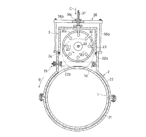
As shown in FIG.l, a seal-up housing 2 consists of the
first half housing 21 and second half housing 22, which
are of a semi-split type, and a cutter attaching housing
(tool attaching housing) 23. As shown in FIG.2, a pair of
left and right seal-up housings 2 and 2 are attached to an
existing pipe 1, and they enclose and seal up, in an
airtight state, two portions spaced from each other in the
axial direction S of pipe on the existing pipe 1. Rubber
rings 24, etc. as shown in FIG.3 are used to seal between
the respective housings 21 and 22 and between both the
-27-
CA 02254656 1998-11-23
slit housings 21 through 23 and the existing pipe 1.
Furthermore, With respect to a sealing structure between
the existing pipe 1 and the respective housings 21 and 22
and between the respective housings 21 and 22, an already
known structure disclosed in, for example, FIG.4 of United
States Patent No.3,650,547 described above may be
employed.
The abovementioned second split housing 22 has a
branch-like guiding portion (bifurcated portion) 22a which
protrudes from the existing pipe 1 in its diametrical
direction C. The abovementioned cutter attaching housing
23 is attached to the corresponding guiding portion 22a so
that it is slidable in its diametrical direction C. A
slit-like opening 22b into which a disk-shaped cutting
tool 30 is inserted is formed at the guiding portion 22a
in the second slit housing 22.
Cutting equipment 3 is attached to each of the cutter
attaching housings 23 of a pair of seal-up housings 2.
That is, a first motor (one example of the prime movers)
31 for rotating a cutting tool is fixed outside the
abovementioned cutter attaching housing 23 while the
abovementioned cutting tool 30 is housed in the
abovementioned cutter attaching housing 23. A bearing
-28-
CA 02254656 1998-11-23
housing 32 is fixed at the cutter attaching housing 23,
and a cutter shaft 33 is rotatably supported in the
bearing housing 32 so that the cutter shaft 33 can be
driven and rotated. The cutting tool 30 is fixed at the
cutter shaft 33. The cutter shaft 33 is provided in
parallel to the axial direction S of an existing pipe 1.
The abovementioned first motor 31 causes the cutting tool
30 to rotate via a drive gear 34 fixed at the output shaft
34A of the first motor 31, a driven gear 35 fixed at the
cutter shaft 33, and the abovementioned cutter shaft 33.
Furthermore, a hydraulic motor, a pneumatic motor, an oil
hydraulic motor or an electric motor may be used as the
abovementioned first motor 31.
The abovementioned cutting tool 30 is, for example, a
diamond wheel.
The corresponding diamond wheel 30 is such that a
number of diamond grains 30c (one example of a number of
blades 30c) are welded, by a YAG laser, to the outer
circumferential portion 30b of a disk-shaped base 30a
shown in FIG.1(b) together with metallic powder. A number
of blades 30c are provided on the outer circumferential
surface and both side surfaces of the base 30a. Although
the corresponding diamond wheel 30 is a cutting tool,
-29-
CA 02254656 1998-11-23
having non-directivity, which is able to slit an existing
pipe 1 even though it rotates in any one of two directions
centering around the cutter shaft 33 in FIG.1(a), it is
preferable that the cutter shaft 33 is caused to rotate in
the rotation direction A1 opposite to the rotation
direction R of the seal-up housing 2 in FIG.1(a). This is
because cutting chips are scarcely discharged into the
existing pipe 1 during slitting.
The abovementioned diamond wheel 30 is suitable for
cutting concrete and stone materials. As for the
corresponding diamond wheel, those made by Robtex, Ltd.
and/or Shibaura Mfg. CO., Ltd. may be used.
Furthermore, a mechanical seal (not illustrated) is
used to seal between the bearing housing 32 and the cutter
shaft 33.
A cutting feed frame 36 is fixed at the abovementioned
guiding portion 22a. The cutting feed frame 36 is provided
with long bolts 36a fixed at the abovementioned guiding
portion 22a and a top plate 36b fixed at the upper ends of
the long bolts 36a. A male lead screw 37 for cutting feed
is screwed in a bushing 36c secured at the top plate 36b
of the abovementioned cutting feed frame 36. By turning
the male lead screw 37 for cutting feed to be screwed in
-30-
CA 02254656 1998-11-23
the cutting direction C (the center direction of the
diametrical direction C of an existing pipe 1), the cutter
attaching housing 23 advances in the cutting direction C.
Therefore, the cutter attaching housing 23 is fed in the
cutting direction C while rotating the abovementioned
cutting tool 30, wherein if the cutting tool 30 is caused
to advance in a slit-like opening 22b in FIG.3, the
cutting tool 30 is fed toward roughly the center in the
diametrical direction of the existing tube 1, thereby
causing the existing pipe 1 to be slit as shown in FIG.4.
As shown in FIG.2, a housing turning device 4 is
disposed between the abovementioned pair of seal-up
housings 2 and 2. The corresponding housing turning device
4 has an annular spacer 40 circumferentially divided into
two sections. The corresponding spacer 40 is to determine
the relative position between a pair of seal-up housings 2
and 2. The spacer 40 is fixed at the existing pipe 1 with
a number of set screws 46 and a liner 41 is provided at
both sides of the spacer 40.
A gear housing 43 is fixed at one of the abovementioned
two-split spacers 40, and a second motor 42 for turning
the seal-up housing is fixed at the corresponding gear
housing 43. The corresponding second motor rotates a pair
-31-
CA 02254656 1998-11-23
of drive gears 44 for turning the seal-up housing, via a
bevel gear 47 and a driven gear 47A, etc., and the
respective drive gears 44 rotates a driven gear 45 for
turning the seal-up housing, which is fixed at the outer
circumference of the first and second split housings 21
and 22. Therefore, the present method is able to cut off
an existing pipe 1 at two points by turning the seal-up
housing 2 once around the existing pipe 1 while causing
the cutting tool 30 to rotate in a cutting feed state
shown in FIG.4 (that is, carrying out a slitting motion).
As shown in FIG.2, an annular slip preventing member 5
is, respectively, secured at the existing pipe 1 outward
of the abovementioned pair of seal-up housings 2 and 2.
The corresponding slip preventing member 5 is divided into
two sections in the circumferential direction R (FIG.1) of
the existing pipe 1, and the slip preventing member 5 is
provided with a number of steel balls 50 and set screws 51
secured alternately in the circumferential direction R
(FIG.1). The slip preventing member 5 is fixed at the
existing pipe 1 by set screws 51. The slip preventing
member 5 presses the seal-up housing 2 to the central side
by the steel balls 50 and nips the seal-up housing 2
between the steel balls 50 and the liners 41 of the
-32-
CA 02254656 1998-11-23
abovementioned housing turning device 4, wherein the seal-
up housing 2 is prevented from slipping and shaking in the
axial direction S of the existing pipe 1. Therefore, the
seal-up housing 2 smoothly turns when turning around the
existing pipe 1. Furthermore, the abovementioned steel
balls 50 are fixed at the slip preventing member 5 so that
their positions are able to be adjusted in the axial
direction S of pipe 1 in FIG.3.
A bar-like valve 25 is secured at the slit-like opening
22b of the abovementioned second split housing 22 in
FIG.3. As shown in FIG.S(a), the corresponding bar-like
valve 25 is provided with a bar-like long valve body 26
and a bar-like valve housing 27. As shown in FIG.5(b) and
FIG.S(c), the abovementioned bar-like valve body 26 is
composed so that half-moon type rubber packing 26b is
formed integral with a metallic core 26a, and so that the
valve body 26 is rotatably attached to the bar-like valve
housing 27. The bar-like valve body 26 allows the cutting
tool 30 to be fed for cutting as shown in FIG.S(b), and on
the other hand, seals the slit-like opening 22b to stop
water by turning the bar-like valve body 26 as shown in
FIG.S(c) after the cutting is finished.
Cutting process
-33-
CA 02254656 1998-11-23
Next, a description is given of a cutting procedure.
First, workmen attach a housing turning device 4 and a spacer
40 to the existing pipe 1 in a state where fluid (water) is
flowing through the existing pipe 1 in FIG.2, and attach a
seal-up housing 2 and slip preventing members 5 to both sides
of the housing turning device 4 , wherein two points spaced from
each other in the axial direction S of the pipe on the existing
pipe 1 are enclosed and sealed up in an airtight state by a
pair of seal-up housings 2 and 2. Cutting equipment 3 is
attached, in advance, to a cutter attaching housing 23 of the
seal-up housing 2. Furthermore, the workmen fix a bar-like
valve 25 by turn-stop bolts 26c in FIG.5 (a) in its open state
as shown in FIG.5 (b) .
Next, as the workmen drive the first motor 31 in FIG.3, the
corresponding first motor 31 rotates the abovementioned
cutting tool 30 on the cutter shaft 33 at a high speed and causes
the cutting tool 30 to perform a slitting motion by which
the existing pipe 1 is slit by rotations of the cutting
tool 30. In a state where the corresponding slitting
motion is being carried out by the cutting tool 30,
as the workmen progressively screw a male lead screw
37 for cutting feed in the cutting direction C,
-34-
CA 02254656 1998-11-23
the cutting tool 30 advances, concurrently, to the position
where the cutting tool 30 passes through a part of the wall
la of the existing pipe 1 as shown with alternate long and two
dashes lines in FIG.1. Thus, cutting feed of the cutting tool
30 in the direction C is completed.
After that, as workmen drive the second motor for turning
the seal-up housing in FIG.2, a pair of seal-up housings 2 are
turned around the existing pipe 1 via a bevel gear 47 and a
pair of drive gears 44 and driven gear 45. Thereby, the cutting
tool 30 in FIG.1 is caused to rotate on the cutter shaft 33
while the cutting tool 30 turns in the direction of the arrow
R along the outer circumference of the existing pipe 1 together
with the seal-up housings 2 , wherein the cutting tool 30 roughly
slits annularly the existing pipe 1 , and finally cuts off the
pipe 1 . That is, with the second motor 42 in FIG.2, the cutting
tool 30 in FIG.4 is turned in the circumferential direction
R by turning the abovementioned seal-up housing 2 in
the circumferential direction R (FIG.1) of the
existing pipe 1, wherein the cutting tool 30 is
caused to perform a feeding motion. Thereby, the
cutting tool 30 cuts off the existing pipel, and a cut-
-35-
CA 02254656 1998-11-23
off section 10 to be removed (a cylindrical cut-off section
in FIG.6) in FIG.4 is formed from the existing pipe 1.
After the cutting-off, the workmen reversely turn the male
lead screw 37 for cutting feed, cause the cutting tool 30 to
slide together with the cutter attaching housing 23, and
retreat the cutting tool 30 to a non-cutting position in FIG.3.
After the cutting tool is retreated, the workmen turn the
bar-like valve body 26 in FIG S (b) by 90 degrees, wherein the
fluid (water) is prevented from flowing out through the
slit-like opening 22b in FIG. 5 (c) . The next eliminating process
of the cut-off section is commenced after the sealing is
finished.
Cut-off section eliminating process
After the cutting off is completed, the workmen remove the
cutting equipment 3 from the existing pipe 1 in FIG.2 together
with the cutting attaching housing 23 . Furthermore, the workmen
remove the slip preventing members 5, housing turning device
4 , spacer 4 0 , etc . , from the existing pipe 1 . Thus , as shown
in FIG.6, the situation is such that the existing pipe 1 is
in a state where only a first split housing 21, second split
housing 22 of the seal-up housing 2 and bar-like valve 25 remain .
After that, the workmen fixes a lifting band 11 to the
-36-
CA 02254656 1998-11-23
cut-off section 10 in order to raise the cut-off section
between both seal-up housings 2 and 2, and at the same
time attach a split type short pipe 6 to both sides of the
seal-up housings 2 and 2 at the existing pipe 1. The split
type short pipe 6 is divided into two sections in the
circumferential direction R (FIG.1) of the existing pipe
1, and is provided with a packing insertion portion 60,
into which rubber packing is inserted, and a plate-like
flange 61, which compresses sheet packing 81 (FIG.12 ) , at
both ends thereof. Furthermore, the corresponding split
type short pipe 6 is provided with an O ring 63 to
temporarily stop water in a groove 62.
Next, as shown in FIG.7, the workmen enclose and seal
up, in an airtight state, both seal-up housings 2 and 2
and split type short pipe 6 together with the existing
pipe 1 by an operation chamber 7, and connect an elevating
shaft 76 to the lifting band 11. The operation chamber 7
consists of operation lower chambers 71 and 72, which are
divided in the perpendicular direction (circumferential
direction), an operation sluice valve 73 and an operation
upper chamber 74. On the other hand, the workmen screw a
pressing rod 75, by which the split type short pipe 6 and
seal-up housing 2 are caused to slide, into the operation
-37-
CA 02254656 1998-11-23
lower chambers 71 and 72 before sealing up by the
abovementioned operation chamber 7 and connect the tip end
of the pressing rod 75 to the split type short pipe 6 via
a connecting metal fitting 75a in FIG. B. The corresponding
pressing rod 75 consists of, for example, a male long
screw. The workmen turns the pressing rod 75 clockwise to
move the split type short pipe 6 to the central side. On
the other hand, by turning the pressing rod 75
counterclockwise, the split type short pipe 6 is returned
sideways.
In a state as shown in FIG.B, if workmen turn the
pressing rod 75 clockwise, the split type short pipe 6 is
pressed and is caused to slide to the central side,
wherein the split type short pipe 6 presses the seal-up
housing 2 to cause the split type short pipe 6 to move to
the central side. After the seal-up housing 2 rides over
the cut-off groove portion 12 and is placed on the cut-off
section 10, the workmen reversely turn the pressing rod
75, only the split type short pipe 6 is returned sideways
(right side) as shown in FIG.9. Thereafter, the workmen
lift up the elevating shaft 76 and take out the cut-off
section 10 together with two seal-up housings 2 and 2 from
the operation lower chambers 71 and 72 to the operation
-38-
CA 02254656 1998-11-23
upper chamber 74 in FIG.10, wherein an operation sluice
valve 73 is closed. After the sluice valve 73 is closed,
workmen remove the cut-off section 10 and seal-up housing
2 together with the operation upper chamber 74.
Furthermore, the workmen may use a lifting device such as
a crane in assembling the abovementioned chamber 74.
Furthermore, in FIG.7, FIG.9, FIG.11, or FIG.13, the
abovementioned 0-ring 63 (FIG.12) for temporarily stopping
water is omitted.
Process for inserting a valve
After the cut-off section 10 is eliminated in FIG.10,
as shown in FIG.11, workmen houses a valve for insertion
such as a butterfly valve 8 in an operation upper chamber
74. The butterfly valve 8 has collar-like flanges 80 and
80 at both ends, and for example, annular sheet packing 81
is cemented to the respective flanges 80 and 80.
Furthermore, when inserting the corresponding butterfly
valve 8, the butterfly valve 8 is kept in its open state
and a speed reducer 82 (FIG.14) is removed from the
butterfly valve 8.
After that, the workmen open the operation sluice valve
73. After the valve is opened, the butterfly valve 8 is
shifted down into the operation lower chambers 71 and 72.
-39-
CA 02254656 1998-11-23
Thereafter, as the pressing rod 75 in FIG.12 is turned
clockwise by workmen and the split type short pipe 6 is
caused to slide toward the butterfly valve 8, as shown in
FIG.13, a plate-like flange 61 of the split type short
pipe 6 is brought into contact with the sheet packing 81
concurrently. In this state, the sheet packing 81 is
compressed between the two plate-like flanges 61 and 80 by
an axial force of the pressing rod 75, wherein it is
attempted that water is temporarily stopped between the
split-type short pipe 6 and butterfly valve 8. On the
other hand, water is also temporarily stopped between the
split-type short pipe 6 and the existing pipe 1 by the
abovementioned O-ring 63 mounted in advance at the split-
type short pipe 6 in FIG.14.
Thereafter, workmen discharge water in the operation
chamber 7 in FIG.13. After water is discharged, the
workmen tighten a pair of plate-like flanges 61 and 80 by
tightening bolts 83 in FIG.14, wherein water is completely
stopped between the split type short pipe 6 and butterfly
valve 8. After that, the workmen disassemble the operation
chamber 7 in FIG.13. After the disassembling is completed,
the workmen attach split-type pressing rings 65 between
the existing pipe 1 and the split-type short pipes 6 and
-40-
CA 02254656 1998-11-23
press water stopping rubber rings 64 into the
abovementioned packing inserting portions 60 of the split-
type short pipe 6. On the other hand, a speed reducer 82
is attached to the butterfly valve 8. Thus, the butterfly
valve 8 which stops water in a line 1A is inserted into
the line 1A including the existing pipe 1.
Thus, in the present cut-off method, since the
abovementioned cutting tool 30 is turned in the outer
circumference of the existing pipe 1 by turning the seal-
up housing 2 when cutting it off in FIG.2, it is not
necessary that a mechanism for turning the cutting tool 30
around the existing pipe 1, that is, a housing turning
device 4 is provided in the seal-up housing 2. Therefore,
downsizing of the seal-up housing 2 is achieved.
Furthermore, with a valve inserting method according to
the invention, although an operation chamber 7 in FIG.7 is
required and the corresponding operation chamber 7 is
remarkably large in comparison with the seal-up housing 2,
the operation chamber 7 is made smaller than that in prior
arts since the seal-up housing 2 from which the cutting
equipment 3 is removed is accommodated by the operation
chamber 7.
-41-
CA 02254656 1998-11-23
Hence, in the abovementioned preferred embodiment,
although a diamond wheel 30 in FIG.1(a) is used as the
abovementioned cutting tool, an end mill 30 in FIG.15(a)
and a metal slitting saw 30B shown in FIG.15(c) may be
used in the invention instead of a disk-shaped cutting
tool 30. The abovementioned metal slitting saw 30B in
FIG.15(c) is composed so that a number of cutting chips
(blades) 30h are brazed to the outer circumferential
portion of a disk-shaped base 30g.
Furthermore, instead of turning the bar-like valve body
26 in the preferred embodiment, a plate-like valve body
26A in FIG.15(b) may be inserted into a slit-like opening
22b in FIG.15(a) to cause water to be stopped by clogging
the opening 22b. Furthermore, with the method for
inserting a valve in a line without stopping water
according to the invention, a sluice valve may be inserted
instead of a butterfly valve.
FIG.16 shows a modified version of the first preferred
embodiment.
In the modified version of the first embodiment, a
cutter attaching housing 23A is rotatably attached to the
second split housing 22A via a hinge 38. The corresponding
-42-
CA 02254656 1998-11-23
cutter attaching housing 23A is fixed at the second split
housing 22A by bolts 39.
In the modified version, in order to cut off the
existing pipe 1, first, the workmen attach the second
split housing 22A, etc., to the existing pipe 1.
Subsequently, the workmen actuate the first motor 31 to
rotate the cutting tool 30 in a state where the cutter
attaching housing 23A is open as shown with an alternate
long and two dashes line in FIG.16(a). From this state,
the workmen cause the cutter attaching housing 23A in the
direction of the arrow around the hinge 38, the cutting
tool 30 also moves in the direction of the arrow and
begins cutting off the existing pipe 1. Concurrently, as
the cutter attaching housing 23A enters a state where the
the slit-like opening 22b of the second split housing 22A,
the cutting tool 30 finishes a cutting feed of the
existing pipe 1. Thereafter, the workmen fix the cutter
attaching housing 23A at the second split housing 22A by
bolts 39 in FIG.16(a). After the cutter attaching housing
23A is fixed, the existing pipe 1 is cut off if the
workmen turn the seal-up housing 2 around the existing
pipe 1 while providing a slitting motion to the cutting
tool 30.
-43-
CA 02254656 1998-11-23
SECOND PREFERRED EMBODIMENT
FIG.17 through FIG.25 show a second preferred
embodiment.
Hereinafter, a description is given, in the order of
processes, of an existing cut-off method and a method for
inserting a valve in a line without stopping passage of
water according to the second preferred embodiment. The
following embodiments including the second preferred
embodiment are suitable for and applicable to small- and
medium-sized pipes having a diameter of 4 inches through
20 inches.
Cutting equipment
As shown in FIG.18, in the preferred embodiment, a
central first seal-up housing 2A and a pair of left and
right second seal-up housings 2B are used. The
abovementioned first seal-up housing 2A is provided with a
first split housing 121 and a second split housings 122,
divided into two sections in the circumferential direction
R as shown in FIG.17, and a two-cutting tool attaching
housing 123. Furthermore, the abovementioned second seal-
up housing 2B (FIG.18) is also divided into two sections
in the circumferential direction. Rubber rings 124, etc.,
-44-
CA 02254656 1998-11-23
are used to seal between these housings 121 and 122, and
2A and 2B, and between the second seal-up housing 2B and
the existing pipe 1 in FIG.19.
The abovementioned second split housing 122 has a
bifurcated portion 122b protruding outward in the
diametrical direction C of the existing pipe 1. The cutter
attaching housing 123 is slidably attached to the
bifurcated portion 122b in the diametrical direction C of
the existing pipe 1 via a guide bushing 122a so that the
cutter attaching housing 123 is permitted to advance and
retreat. An opening 122C into which two disk-shaped
cutting tools 130 are inserted is formed at the
abovementioned bifurcated portion 122b at the second split
housing 122.
Cutting equipment 3 is attached to the cutter attaching
housing (tool attaching housing) 123 of the first seal-up
housing 2A. That is, a first motor (one example of a prime
mover) 131 for rotating the tools is fixed upward of the
abovementioned cutter attaching housing 123. On the other
hand, the abovementioned two cutting tools 130 are
disposed in the abovementioned cutter attaching housing
123. It is preferable that a diamond wheel having the same
structure as that of the first preferred embodiment is
-45-
CA 02254656 1998-11-23
used as the corresponding cutting tool 130. These cutting
tools 130 are disposed so as to be spaced from each other
in the axial direction S of pipe 1 and are fixed at the
cutter shaft 133. The cutter shaft 133 is rotatably
supported at a bearing housing 132 fixed at the cutter
attaching housing 123 so that it is able to be driven and
rotated. The first motor 131 causes the cutting tools 130
to rotate via the output shaft of the first motor 131, a
bevel gear 134 attached to the cutter shaft, and the
cutter shaft 133.
A cutting feed frame 136 is fixed at the bifurcated
portions 122b, and the corresponding cutting feed frame
136 is provided with long bolts 136a fixed at the
bifurcated portions 122b and a top plate 136b fixed at the
upper ends of the long bolts 136a. A cutting feed male
lead screw 137 is screwed in a bushing 136c secured at the
top plate 136b of the cutting feed frame 136.
By turning and screwing the abovementioned cutting feed
male lead screw 137 in the cutting feed direction C, the
cutter attaching housing 123 advances in the cutting feed
direction C. Therefore, the cutter attaching housing 123
is sent in the cutting feed direction C to cause the
cutting tools 130 to go into the opening 122C while
-46-
CA 02254656 1998-11-23
rotating the cutting tools 130, wherein as shown in
FIG.20, it is possible to slit the existing pipe 1 by the
abovementioned cutting tools 130. Furthermore, since the
guide bushing 122a is fixed at the top plate 136b via a
connection metal fitting 138 in FIG.17, it is collected
together with the cutting feed frame 136 after the cutting
is completed.
As shown in FIG.17, a lifting belt 11A is wound onto
the existing pipe 1 and cutter shaft 133, by which a
freshly cut-off section 10 in FIG.21 is collected together
with the cutting equipment 3 after cutting off the
existing pipe 1. Furthermore, the lifting belt 11A is such
that as in FIG.17, a flexible rubber plate portion 11a, a
thin metal belt 11b, and a connection piece llc are
united.
In the preferred embodiment, a housing turning device 4
shown in FIG.18 is provided, which causes the first seal-
up housing 2A to be turned around the existing pipe 1. The
housing turning device 4 has a pair of second motors 142
for turning the seal-up housing. The corresponding second
motors 142 rotates drive gears 144, which turn the seal-up
housing, via the respective output shafts 147. The
corresponding drive gears 144 driven gears 145, which
-47-
CA 02254656 1998-11-23
turns the seal-up housing fixed at the first seal-up
housing 2A. Therefore, by turning the first seal-up
housing 2A to be turned around the existing pipe 1 once
while rotating the cutting tools 130 in a cutting feed
state as shown in FIG.20, the existing pipe 1 can be cut
off at two points.
As shown in FIG.19, the second seal-up housing 2B
constitutes a slip preventing member 5A. The corresponding
second seal-up housing 2B is divided into two divisions in
the circumferential direction R (FIG.17). The second seal-
up housing 2B has a number of set screws 151 provided in
the circumferential direction R (FIG.17) at each of the
two points spaced from each other in the axial direction S
of pipe 1. A rotation guiding portion 150 which slides via
a liner 152 is provided at the connection portion between
the first seal-up housing 2A and the second seal-up
housing 2B. The second seal-up housing 2B is fixed at the
existing pipe 1 by the abovementioned set screws 151. The
abovementioned pair of second seal-up housings 2B guides
the first seal-up housing 2A via the abovementioned
rotation guiding portion 150 and prevents the first seal-
up housing 2A from slipping or shaking in the axial
direction S of the existing pipe 1. Therefore, the first
-48-
CA 02254656 1998-11-23
seal-up housing 2A is able to be smoothly turned when
turning around the existing pipe 1. Furthermore, a ball
bearing may be used instead of the liner 152.
Cutting process
Next, a description is given of a cutting process.
First, in a state where fluid (water) is flowing
through the existing pipe 1 in FIG.17, the workmen apply
the upper half member of the first and second seal-up
housings 2A and 2B (in FIG.18) onto the existing pipe 1,
and wind the lifting belt 11A onto the cutter shaft 133
and existing pipe 1. Thereafter, the workmen tighten the
lower half member of the first and second seal-up housings
2A and 2B together with the upper half member by assembly
bolts 128. Thus, the existing pipe 1 is enclosed and
sealed up, in an airtight state, by the first and second
seal-up housings 2A and 2B. Furthermore, the workmen
attach, in advance, the cutting equipment 3 to the cutter
attaching housing 123 of the first seal-up housing 2A.
Next, as the workmen drive the first motor 131 in
FIG.19, the corresponding first motor 131 rotates the
abovementioned cutting tools 130 on the cutter shaft 133
at a high speed, wherein the abovementioned cutting tools
130 are caused to perform a slitting motion by which the
-49-
CA 02254656 1998-11-23
existing pipe 1 is slit by rotations of the corresponding
cutting tools 130. In the state where the cutting tool 130 is
performing the corresponding slitting motion, if the workmen
screws the male lead screw 137 for cutting feed in the direction
C, concurrently, the abovementioned cutting tools 130 advance,
as shown with an alternate long and two dashes line in FIG.17,
to the position where the cutting tools 130 pass through a part
of the wall la of the existing pipe 1. Thus, cutting feed of
the cutting tools 130 in the direction C is completed.
After the cutting feed, if the workmen drive the secondmotor
142 for turning the seal-up housing, the first seal-up housing
2A is turned around the existing pipe 1 via a pair of drive
gears 144 and driven gears 145 in FIG.20, in a state where the
first seal-up housing 2A is guided by the second seal-up housing
2B. Thereby, the cutting tools 130 shown in FIG.17 are rotated
on the cutter shaft 133 while turning in the direction of the
arrow R along the outer circumference of the existing pipe 1
together with the first seal-up housing 2A, wherein as shown
in FIG.21, the existing pipe 1 is slit to be roughly annular
at two points to cut off the existing pipe 1. That is, the
abovementioned second motor 142 shown in FIG.18 causes the
-50-
CA 02254656 1998-11-23
cutting tools 130 in FIG.20 to turn in the circumferential
direction R by turning the first seal-up housing 2A in the
circumferential direction R (FIG.17) of the existing pipe
1, thereby causing the cutting tools 130 to perform a
feeding motion. Therefore, the cutting tools 130 cut off
the abovementioned existing pipe 1.
After the corresponding cutting is completed, the
workmen remove the housing turning device 4 (in FIG.18).
Furthermore, cutting chips may be discharged through a
water discharge valve by attaching the discharge valve to
the cutter attaching housing 123.
Cut-off section removing process
Next, the workmen remove the cutting equipment 3 and
freshly cut-off section 10 by the method described below.
As shown in FIG.21, the workmen connect an operation
sluice valve 173 to the bifurcated portion 122b and
further connect an operation upper chamber 174 to the
abovementioned operation sluice valve 173 so as to overlap
thereon. At the point of the connection, the workmen
connect a cutting feed frame 136 to the tip end of an
lifting shaft 176 passing through the operation upper
chamber. After the connection is completed, the workmen
remove nuts 139. After removing the nuts, the workmen
-51-
CA 02254656 1998-11-23
raise the lifting shaft 176 in FIG.22 to remove the
cutting equipment 3 and cut-off section 10 from the first
seal-up housing 2A into the operation upper chamber 174.
After that, the operation sluice valve 173 is closed.
After the valve is closed, the workmen separate the
operation upper chamber 174 from the operation sluice
valve 173.
Valve inserting process
Next, the workmen accommodate a valve cover 8b in
FIG.23 and sluice valve body 8a into the operation upper
chamber 174 and connect the operation upper chamber 174 to
the operation sluice valve 173. The sluice valve 8A is
provided with a spindle 8c for opening and closing the
sluice valve body 8a. The sluice valve 8A constitutes a
valve so that, if the spindle 8c is turned, the sluice
valve body 8a invades the cut-open portion 12B and rubber
packing 8d secured at the sluice valve body 8a is
pressure-fitted to the inner circumferential portions,
etc., of the first seal-up housing in FIG.25.
After the operation upper chamber 174 shown in FIG.23
is attached, the workmen open the operation sluice valve
173 as shown in FIG.24 and lower the lifting shaft 176.
Thereby, the valve cover 8b is brought into contact with
-52-
CA 02254656 1998-11-23
the bifurcated portion 122b. After they are brought into
contact with each other, the workmen connect the valve
cover 8b to the bifurcated portion 122b by flange bolts
8e. After the connection is completed, the workmen
withdraw the operation upper chamber 174 and operation
sluice valve 173. Thereafter, the workmen press rubber
rings 164 into the packing insertion portions 160 of the
second seal-up housing 2B in FIG.25 and attach the split
press rings 165 to the second seal-up housing 2B. Thus,
the sluice valve 8A is disposed at the position
corresponding to the cut-open portion 12B and the sluice
valve 8A is inserted into a line 1A.
FIG.26 through FIG.28 show a modified version of the
embodiment.
As shown in the modified version, the lifting belt 11A
may be attached to the bifurcated portion 122b.
Furthermore, as shown in FIG.27, the output of the first
motor 131 may be transmitted to the cutter shaft 133 via a
timing belt 135. Moreover, at the point of cutting shown
in FIG.28, a guide roller 146 which bites the outer
surface of the existing tube 1 and guides the cutting
equipment 3 may be provided. Furthermore, the cutter shaft
133 is rotatably supported at an eye bolt 133A.
-53-
CA 02254656 1998-11-23
THIRD PREFERRED EMBODIMENT
FIG.29 through FIG.37 show a third preferred
embodiment.
Hereinafter, a description is given, in the order of
processes, of an existing pipe cut-off method and a method
for inserting a valve in a line without stopping passage
of water according to the third preferred embodiment.
Cutting equipment
As shown in FIG.30, in the preferred embodiment, a
first central seal-up housing 2A and a pair of left and
right second seal-up housings 2B are used. The first seal-
up housing 2A is equipped with, as shown in FIG.29, the
first and second split housings 221 and 222, which are
split into two sections in the circumferential direction,
and a guide bushing 222a. Furthermore, the abovementioned
second seal-up housing 2B (FIG.30) is divided into two
divisions. As shown in FIG.31(a), rubber rings 224, etc.
are used to seal up between these housings 221 and 222,
and 2A and 2B, and the second seal-up housing 2B and the
existing pipe 1.
The abovementioned second split housing 222 has a
bifurcated portion 222b protruding from the existing pipe
-54-
CA 02254656 1998-11-23
1 in the diametrical direction C. A main bearing (tool
attaching housing) 232 is secured at the bifurcated
portions 222b via the abovementioned guide bushing 222a so
that the main bearing is able to slidably be advanced and
retreated in the diametrical direction C of the existing
pipe 1. Rubber rings 224 are used to seal up between the
abovementioned guide bushing 222a, bifurcated portions
222b and main bearing 232. An opening 222c into which an
end mill (cutting tool) 230 is inserted is formed at the
abovementioned bifurcated portions 222b at the second
split housing 222.
Cutting equipment 3 is attached to the guide bushing
222a fixed at the abovementioned first seal-up housing 2A
via the main bearing 232. That is, the first motor 231 (an
example of a prime mover) for rotating a tool is fixed
upward of the main bearing 232. On the other hand, the
abovementioned end mill 230 is disposed inside the
abovementioned main bearing 232. The end mill 230 is
formed integral with the main shaft 233 (cutter shaft)
rotatably supported on the main bearing 232. The first
motor 231 rotates the end mill 230 via the output shaft
231a of the first motor 231 and a coupling 234 fixed at
the main shaft 233.
-55-
CA 02254656 1998-11-23
As shown in FIG.31(b), the abovementioned end mill 230
is provided with a plurality of blades 230f at the
columnar tip end surface 230d and the outer
circumferential surface 230e thereof. Furthermore, the
abovementioned main shaft 233 is formed at the end mill
230 integral therewith. As shown in FIG.29, the axial line
233a of the abovementioned end mill 230 and main shaft 233
is set in the diametrical direction C of the existing pipe
1. The abovementioned end mill 230 carries out a slitting
motion by rotating around the axial line 233a established
in the diametrical diameter C of the abovementioned
existing pipe 1.
A cutting feed frame 236 is fixed at the abovementioned
bifurcated portions 222b in FIG.31(a). The cutting feed
frame 236 is provided with long bolts 236a fixed at the
abovementioned bifurcated portions 222b and a top plate
236b fixed at the upper end of the corresponding long
bolts 236a. A mail lead screw 237 for cutting feed is
screwed in a bushing 236c secured at the abovementioned
top plate 236b of the abovementioned cutting feed frame
236.
By turning and screwing the corresponding male lead
screw 237 for cutting feed in the cutting feed direction
-56-
CA 02254656 1998-11-23
C, the main bearing 232 advances in the cutting feed
direction C. Therefore, by feeding the end mill 230
together with the main bearing 232 in the cutting feed
direction C while rotating the end mill 230 and causing
the end mill 230 to advance into the opening 222c, it is
possible to slit the existing pipe 1 by the end mill 230
as shown in FIG.32. Furthermore, the guide bushing 222a is
fixed at the cutting feed frame 236 via a connection metal
fitting 238 in FIG.29, and it is designed so that it can
be collected together with the cutting feed frame 236
after the cutting is completed.
In the preferred embodiment, a housing turning device
4, shown in FIG.30, which causes the first seal-up housing
2A to rotate around the existing pipe 1, is provided. The
housing turning device 4 has a pair of second motors 242
for turning the seal-up housing. The corresponding second
motors 242 rotate drive gears 244 for turning the seal-up
housing via their output shafts 247. The corresponding
drive gears 244 rotate driven gears 245 for turning the
seal-up housing, which are fixed at the first seal-up
housing 2A. Therefore, by causing the first seal-up
housing 2A to turn once around the existing pipe 1 while
-57-
CA 02254656 1998-11-23
rotating the end mill 230 in a cutting feed state in
FIG.32, it is possible to cut off the existing pipe 1.
As shown in FIG.31, the second seal-up housing 2B
constitutes a slip preventing member 5A. The corresponding
second seal-up housing 2B is divided into two sections in
the circumferential direction R (FIG.29) of the existing
pipe 1. A number of set screws 251 are secured at two
points spaced from each other in the axial direction S of
pipe 1 at the corresponding second seal-up housing 2B, in
the circumferential direction R (FIG.29). A rotation
guiding portion 250 which slides via a liner 252 is
provided at the connection portion between the first seal-
up housing 2A and the second seal-up housing 2B. The
abovementioned pair of second seal-up housings 2B are
fixed at the existing pipe 1 by the set screws 251. The
abovementioned second seal-up housings 2B guide the first
seal-up housing 2A via the abovementioned rotation guiding
portion 250 and prevent the first seal-up housing 2A from
slipping or shaking in the axial direction S of the
existing pipe 1. Therefore, the first seal-up housing 2A
is able to be smoothly turned when turning around the
existing pipe 1. Furthermore, a ball bearing may be used
instead of the liner 252.
-58_
CA 02254656 1998-11-23
Cutting process
Next, a description is given of a sequence of cutting.
First, the workmen attach the first and second seal-up
housings 2A and 2B to the existing pipe 1 in a state where
fluid (water) is flowing through the existing pipe 1 in
FIG.30, and assemble both split housings 221 and 222 by
assembling bolts 228 in FIG.29. Thus, as shown in FIG.30,
the first and second seal-up housings 2A and 2B enclose
and seal up the existing pipe 1 in an airtight state.
Furthermore, the cutting equipment 3 is attached, in
advance, to the guide bushing 222a of the first seal-up
housing 2A.
Next, as the workmen drive the first motor 231 in
FIG.29, the corresponding first motor 231 causes the end
mill 230 to rotate around the axial line 233a of the main
shaft 233 and causes the cutting tool 230 to perform a
slitting motion by which the existing pipe 1 is slit by
rotations of the end mill 230. In a state where the
corresponding cutting tool 230 is performing a slitting
motion, if the workmen screw the male lead screw 237 for
cutting feed in the cutting feed direction C,
concurrently, the tip end face 230d of the end mill 230
(FIG.31(b)) advances to the position where it passes
-59-
CA 02254656 1998-11-23
through a part of the wall la of the existing pipe 1. Thus,
the cutting feed of the end mill 230 in the direction C is
completed.
After that, the workmen drive the second motor 242 for
turning the seal-up housing in FIG.30, the first seal-up
housing 2A is turned around the existing pipe 1 via a pair of
drive gears 244 and driven gears 245 in FIG.32 in a state where
it is guided by the second seal-up housing 2B. Thereby, the
end mill 230 rotates on the main shaft 233 while turning in
the outer circumference of the existing pipe 1 together with
the first seal-up housing 2A, wherein, by slitting the existing
pipe 1 roughly annularly, the existing pipe 1 is cut off.
That is, the abovementioned secondmotor 242 (FIG.29) causes
the end mill 230 to be turned in the circumferential direction
R (FIG.29) by turning the abovementioned first seal-up housing
2A in the abovementioned circumferential direction R of the
existing pipe 1 in order to perform a feed motion of the end
mill 230, wherein the end mill 230 annularly slits the
existing pipe 1 and cuts off the abovementioned
existing pipe 1. After the cutting is completed, the
workmen remove the housing turning device 4 in FIG.30.
-60-
CA 02254656 1998-11-23
Furthermore, if a water discharge valve is attached to
the main bearing 232, cutting chips may be discharged
through the water discharge valve when carrying out a
slitting motion.
Cutting equipment removing process
Next, the workmen remove the cutting equipment 3 by the
method described below. That is, as shown in FIG.33, the
operation sluice valve 273 is connected to the bifurcated
portion 222b, and furthermore an operation upper chamber
274 is connected to the operation sluice valve 273 so as
to overlap thereon. When connecting them, the workmen
connect a cutting feed frame 236 to the tip end portion of
a lifting shaft 276 which passes through the the operation
upper chamber 274. After the connection is finished, the
workmen remove nuts 239. After the nuts are removed, the
workmen raise the lifting shaft 276 in FIG.34 and remove
the cutting equipment 3 from the first seal-up housing 2A
into the operation upper chamber 274. After the cutting
equipment 3 is removed, the workmen close the operation
sluice valve 273. After the valve is closed, the workmen
separate the operation upper chamber 274 from the
operation sluice valve 273.
Valve inserting process
-61-
CA 02254656 1998-11-23
Next, the workmen accommodate the valve cover 8b in
FIG.35 and the sluice valve body 8a in the operation upper
chamber 274 and connect the corresponding upper chamber
274 to the operation sluice valve 273. The sluice valve 8A
is provided with a spindle 8c for opening and closing the
sluice valve body 8a. The sluice valve 8A constitutes a
valve so that rubber packing 8d secured at the sluice
valve body 8a is pressure-fitted to the inner
circumferential surface, etc. of the first seal-up housing
2A in FIG.37 as the sluice valve body 8a invades the cut-
open portion 12 by turning the spindle 8c. That is, the
first seal-up housing 2A constitutes a valve housing of
the sluice valve 8A.
After the operation upper chamber 274 in FIG.35 is
mounted, the workmen open the operation sluice valve 273
as shown in FIG.36 and shift down the lifting shaft 276,
wherein the valve cover 8b is brought into contact with
the bifurcated portion 222b. After they are brought into
contact with each other, the workmen connect the valve
cover 8b to the bifurcated portion 222b by flange bolts
8e. After the connection is finished, the workmen withdraw
the operation upper chamber 274 and operation sluice valve
273. Thereafter, the workmen press rubber rings 264 into
-62-
CA 02254656 1998-11-23
the packing insertion portions 260 of the second seal-up
housing 2B in FIG.37 and attach the split press rings 265
to the second seal-up housings 2B. Thus, the sluice valve
8A is disposed at the position corresponding to the cut-
open portion 12, and the sluice valve 8A is inserted in a
line.
FOURTH PREFERRED EMBODIMENT
FIG.38 through FIG.49 show a fourth preferred
embodiment.
Hereinafter, a description is given, in the order of
processes, of an existing pipe slitting method and a
method for inserting a valve in a line without stopping
passage of water according to the fourth preferred
embodiment. Cutting equipment and fixtures for operation,
which are used in the fourth preferred embodiment, are
almost the same as those in the third preferred
embodiment. However, in order to make them doubly sure,
their description is given below.
Cutting equipment (Slitting equipment)
As shown in FIG.39, in the preferred embodiment, a
first central seal-up housing 2A and a pair of left and
right second seal-up housings 2B are used. As shown in
-63-
CA 02254656 1998-11-23
FIG.38, the abovementioned first seal-up housing 2A is
provided with a first and second split housings 221 and
222, which are obtained by being divided into two sections
in the circumferential direction, and a guide bushing
222a. Furthermore, the second seal-up housings 2B (FIG.39)
are also divided into two sections in the circumferential
direction. As shown in FIG.40(a), rubber rings 224 are
used to seal up between the respective housings 221
(FIG.39), 222, 2A and 2B and between the second seal-up
housings 2B and the existing pipe 1.
The abovementioned second split housing 222 has a
bifurcated portion 222b protruding in the diametrical
direction C of the existing pipe 1, and the main bearing
232 is attached to the abovementioned bifurcated portion
222b so as to freely advance and retreat in the
diametrical direction C of the existing pipe 1 via the
guide bushing 222a. Rubber rings 224 are used to seal up
between the guide bushing 222a, bifurcated portion 222b
and the main bearing 232. An opening 222c into which a
columnar cutting tool 230 is inserted is formed at the
abovementioned bifurcated portion 222b at the second split
housing 222.
-64-
CA 02254656 1998-11-23
Cutting equipment 3 is attached to the guide bushing
222a fixed at the abovementioned first seal-up housing 2A
via the main bearing 232. That is, a first motor 231 (an
example of a prime mover) for rotating a cutting tool is
fixed upward of the main bearing 232. On the other hand,
the cutting tool 230 is disposed inside of the
abovementioned main bearing 232 (cutter attaching
housing). A cutting tool 230 is formed to be integral with
the main shaft (cutter shaft) 233 rotatably supported at
the main bearing 232. The first motor 231 causes the
cutting tool 230 to rotate via a coupling 234 fixed at the
output shaft 231a of the first motor 231 and the main
shaft 233.
As shown in FIG.40(b), the abovementioned cutting tool
230 has a plurality of blades 230f on the roughly columnar
tip end surface 230d and outer circumferential surface
230e. Furthermore, the main shaft 233 is formed on the
cutting tool 230 to be integral therewith. As shown in
FIG.38, the axial line 233a of the cutting tool 230 and
main shaft 233 is established in the diametrical direction
C of the existing pipe 1. The cutting tool 230 carries out
a cutting motion by rotating around the axial line 233a
set in the diametrical direction C of the existing pipe 1.
-65-
CA 02254656 1998-11-23
Furthermore, in the preferred embodiment, a cutting tool
230 having a greater diameter than that of the cutting
tool 230 in the third preferred embodiment is used.
Moreover, the tip end of the cutting tool 230 is pointed
to be conical.
A cutting feed frame 236 is fixed at the abovementioned
bifurcated portion 222b in FIG.40(a). The cutting feed
frame 236 is provided with long bolts 236a fixed at the
bifurcated portion 222b and a top plate 236b fixed at the
upper ends of the long bolts 236a. A male lead screw 237
for cutting feed is screwed in a bushing 236c secured at
the abovementioned top plate 236b of the cutting feed
frame 236.
By turning and screwing the male lead screw 237 for
cutting feed in the cutting feed direction C, the main
bearing 232 advances in the cutting feed direction C.
Therefore, by feeding the cutting tool 230 together with
the main bearing 232 in the cutting feed direction C and
causing the cutting tool to be advanced into the opening
222c, it is possible to slit the existing pipe 1 by the
cutting tool 230 as shown in FIG.41. Furthermore, since
the guide bushing 222a is fixed at the cutting feed frame
236 via a connection metal fitting 238 in FIG.38, the
-66-
CA 02254656 1998-11-23
guide bushing 222a can be withdrawn together with the
cutting feed frame 236 after the slitting is completed.
In the preferred embodiment, a housing turning device 4
in FIG.39 is provided, which turns the first seal-up
housing 2A around the existing pipe 1. The housing turning
device 4 has a pair of second motors 242 for turning the
seal-up housing. The corresponding second motor 242
rotates the drive gear 244 for turning the seal-up housing
via the output shaft 247. The corresponding drive gear 244
rotates the driven gears 245 for turning the seal-up
housing, which are fixed at the first seal-up housing 2A.
Therefore, by turning the first seal-up housing 2A by
approximately 180 degrees around the existing pipe 1 while
rotating the cutting tool 230 in a cutting feed state in
FIG.41, it is possible to slit the existing pipe 1 and to
form a slit groove 12C in FIG.45.
As shown in FIG.40, the second seal-up housing 2B
constitutes a slip preventing member 5A. The corresponding
second seal-up housing 2B is divided into two sections in
the circumferential direction (R) (FIG.38) of the existing
pipe 1. A number of set screws 251 are provided in the
circumferential direction R (FIG.38) at two points spaced
from each other in the axial direction S of pipe 1. A
-67-
CA 02254656 1998-11-23
rotation guiding portion 250 which slides via a liner 252
is secured at the connection portion between the
abovementioned first seal-up housing 2A and the second
seal-up housing 2B. The abovementioned pair of second
seal-up housings 2B are fixed at the existing pipe 1 by
the abovementioned set screws 251. The abovementioned
second seal-up housings 2B guide the first seal-up housing
2A via the abovementioned rotation guiding portion 250 and
prevent the first seal-up housing 2A from slipping or
shaking in the axial direction S of the existing pipe 1.
Therefore, the first seal-up housing 2A is able to be
smoothly turned when turning around the existing pipe 1.
Furthermore, a ball bearing may be used instead of a liner
252.
Slitting process
Next, a description is given of a sequence of slitting.
First, in a state where fluid (water) is flowing in the
existing pipe 1 in FIG.39, the workmen attach the first
and second seal-up housings 2A and 2H to the existing pipe
1 and both split housings 221 and 222 by assembling bolts
in FIG.38. Thus, as shown in FIG.39, the first and second
seal-up housings 2A and 2B enclose and seal up the
existing pipe 1 in an airtight state. Furthermore, the
-68-
CA 02254656 1998-11-23
cutting equipment 3 is attached, in advance, to the guide
bushing 222a of the first seal-up housing 2A.
Next, as shown in FIG.42(a) and FIG.42(b), a position to
be slit by a cutting tool 230 is determined. That is, the housing
turning device 4 in FIG.39 is driven, wherein the first seal-up
housing 2A and cutting equipment 3 are turned until the position
wherein the axial line 233a (FIG.42) of the cutting tool 230
is made roughly horizontal.
Next, as the workmen drive the first motor 231 in FIG.38,
the corresponding first motor 231 rotates the cutting tool 230
around the axial line 233a of the main shaft 233, wherein the
cutting tool 230 is caused to perform a slitting motion by which
the existing pipe 1 is slit by rotations of the cutting tool
230. In a state where the cutting tool 230 is performing a
slitting motion, the workmen screw the male lead screw 237 for
cutting feed in the cutting feed direction C, concurrently,
as shown by an alternate long and two dashes line in FIG. 42 (b) ,
the cutting tool 230 advances to the position where the tip
end surface 230d thereof passes through a part of the wall la
of the existing pipe 1. Thus, the cutting feed of
the cutting tool 230 in the direction C is completed.
-69-
CA 02254656 1998-11-23
After that, as the workmen drive the second motor 242 for
turning the housing in FIG.39, the first seal-up housing 2A
is turned, via a pair of drive gears 244 and driven gears 245,
around the existing pipe 1 in a state where it is guided by
the second seal-up housings 2B. Thereby, as shown in FIG. 42 (c) ,
the cutting tool 230 rotates on the main shaft 233 while turning
along the outer circumference of the existing pipe 1 by
approximately 180 degrees (for example, 160 degrees) together
with the first seal-up housing 2A, wherein the existing pipe
is semi-annularly slit to form a slit groove 12C thereat. The
corresponding slit groove 12C is cut open in a range of
approximately 180 degrees in the circumferential direction R
of the existing pipe 1.
That is, the abovementioned second motor 242 (FIG.38) turns
the cutting tool 230 in the circumferential direction R by
causing the first seal-up housing 2A to be turned in the
circumferential direction R (FIG.38) of the existing pipe 1,
as shown in FIG. 42 (b) and FIG. 42 (c) , a cutting feed motion is
given to the cutting tool 230. Thereby, the cutting
tool 230 semi-annularly slits the abovementioned
existing pipe 1 in order to form a slit groove 12C
at the existing pipe 1. After the corresponding
_70_
CA 02254656 1998-11-23
slitting is completed, the cutting tool 230 is returned to
its original position as shown by the arrow of an
alternate long and two dashes line. Thereafter, the
workmen remove the housing turning device 4 in FIG.39.
Furthermore, by attaching a water discharge valve at
the main bearing 232, cutting chips may be discharged
through the water discharge valve when slitting.
Cutting equipment removing equipment
Next, the workmen remove the cutting equipment 3 by the
method described below. That is, as shown in FIG.43, the
workmen connects an operation sluice valve 273 to the
bifurcated portion 222b, and furthermore an operation
upper chamber 274 is connected to the operation sluice
valve 273 so as to overlap thereon. When carrying out the
connection, the workmen connect a frame 236 for cutting
feed to the tip end of a lifting shaft 276 passing through
the operation upper chamber 274. After the connection is
finished, the workmen remove nuts 239. After the nuts 239
are removed, the workmen raise the lifting shaft 276 in
FIG.44 and remove the cutting equipment 3 from the first
seal-up housing 2A into the operation upper chamber 274.
After the cutting equipment is removed, the workmen close
the operation sluice valve 273. After the valve is closed,
-71-
CA 02254656 1998-11-23
the workmen separate the operation upper chamber 274 from
the operation sluice valve 273.
Next, a description is given of a structure of sluice
valve body of a valve to be inserted in a line.
A valve is provided with a sluice valve body 8a shown
in FIG.45. The corresponding sluice valve body 8a is
provided with rubber packing 8d. The corresponding rubber
packing 8d closes the slit groove 12C as the sluice valve
body 8a invades inside of the existing packing 1 through
the slit groove 12C, and is pressure-fitted to the inner
surface 1b of the existing pipe 1. That is, the rubber
packing 8d consists of a first rubber packing portion 8d1
pressure-fitted to the slit surface 12f of the slit groove
12C and a second rubber packing portion 8d2 pressure-
fitted to the inner circumferential surface 1b of the
existing pipe 1 in a series as shown in FIG.46(c) and
FIG.46(d). Furthermore, a first attaching groove 8a1 and a
second attaching groove 8a2 are formed at the
abovementioned sluice valve body 8a in order to attach the
first and second rubber packing portions 8d1 and 8d2 which
are shown in FIG.46(a) and FIG.46(b).
Valve inserting process
-72-
CA 02254656 1998-11-23
Next, the workmen accommodate the valve cover 8b in
FIG.47 and the abovementioned sluice valve body 8a in the
operation upper chamber 274 and connect the corresponding
operation upper chamber 274 to the operation sluice valve
273. The sluice valve 8A is provided with a spindle 8c for
opening and closing the sluice valve body 8a. The
corresponding sluice valve 8A constitutes a valve so that
the sluice valve body 8a in FIG.45 invades the existing
pipe 1 through the slit groove 12C and the rubber packing
8d secured at the sluice valve body 8a is pressure-fitted
to the cutting surface 12f of the existing pipe 1 and the
inner circumferential surface 1b of the existing pipe 1.
That is, the existing pipe 1 constitutes a part of the
valve housing of the sluice valve 8A.
After the operation upper chamber 274 in FIG.47 is
attached in place, the workmen opens the operation sluice
valve 273 as shown in FIG.48 and shifts down the lifting
shaft 276, wherein the valve cover 8b is brought into
contact with the bifurcated portion 222b. After the valve
cover 8b is brought into contact therewith, the workmen
connect the valve cover 8b to the bifurcated portion 222b
by flange bolts 8e. After the connection, the workmen
withdraw the operation upper chamber 274 and operation
-73-
CA 02254656 1998-11-23
sluice valve 273. Thereafter, the workmen press rubber
rings 264 into the packing insertion portions 260 of the
second seal-up housing 2B in FIG.49 and attach split press
rings 265 to the second seal-up housing 2B. Thus, the
sluice valve 8A is disposed at the point corresponding to
the slit groove 12C, wherein the sluice valve 8A is
inserted in a line 1A.
Herein, in the fourth preferred embodiment, since
rubber packing 8d is pressure-fitted to the slitting
surface 12f and the inner circumferential surface 1b of
the existing pipe 1 in FIG.45, that is, the existing pipe
1 is used as a valve housing, a great external force is
applied to the existing pipe 1. However, in this preferred
embodiment, the width of a slit groove 12C formed at the
existing pipe 1 is made small, in particular no thin
portion is produced at the existing pipe 1, and there is
no fear that the existing pipe 1 is damaged when the line
1A is closed with a sluice valve body 8a.
Furthermore, since, when the sluice valve body 8a is
closed, the sluice valve body 8a is supported in the axial
direction S of pipe 1 on the slitting surface 12f via the
first rubber packing portion 8a1, the valve body 8a is
scarcely deformed even though it is given pressure when
-74-
CA 02254656 1998-11-23
stopping water. Therefore, it is possible to make the
spindle 8c slender. Furthermore, since the width of the
slitting groove 12C is small, the force, with which the
valve body 8a is pressed upward by hydraulic pressure, is
also small. Therefore, the spindle 8c can be made slender.
Furthermore, in the abovementioned second preferred
embodiment through the fourth embodiment, although a seal-
up housing is divided into the first seal-up housing 2A
and second seal-up housing 2B and a part of the seal-up
housing, that is, the first seal-up housing 2A is turned,
in the present invention, the first seal-up housing 2A and
second seal-up housing 2B may be formed to be integral
with each other. In this housing, a slip preventing member
is separately provided aside of the seal-up housing,
wherein the entire seal-up housing is turned. This example
is shown by the following modified version of the
embodiments.
Modified version
FIG.50 through FIG.61 show a modified version of the
fourth preferred embodiment.
-75-
CA 02254656 1998-11-23
Hereinafter, after a description is given of the seal-
up housing of the present modified version, a description
is given of a piping structure thereof.
Seal-up housing
As shown in FIG.50(a), the seal-up housing 2 is divided
into the first and second split housings 211 and 212,
wherein the split surface 215 is sealed up by rubber
packing 214 shown in FIG.50(b). Furthermore, the split
surface 215 of the two split housings 211 and 212 is
constructed so that they are brought into contact with
each other in a metal-to-metal touching state.
Furthermore, a packing insertion portion 260 into which
rubber packing 264 in FIG.52 is inserted is provided at
both ends of the seal-up housing 2.
As shown in FIG.51(b), a bolt insertion opening 217 for
fixing a valve cover and a bolt insertion opening 218 for
fixing an operation sluice valve are formed at a flange
216 of the second split housing 212 in FIG.51(a). A hole
219 is to insert an assembling bolt thereinto.
Piping structure
FIG.52 through FIG.55 show a piping structure.
In FIG.52, a slit groove 12C is formed at the existing
pipe 1. As shown in FIG.53, the corresponding slit groove
-76-
CA 02254656 1998-11-23
12C is notched and cut open in a range of approximately
180 degrees in the circumferential direction of the
existing pipe 1. The corresponding slit groove 12C is
formed by slitting the existing pipe 1 by a cutting tool
described later. As shown in FIG.52, the corresponding
groove 12C is formed so that both ends 12c1 thereof in the
circumferential direction is made roughly U-shaped. Thus,
since both ends 12c1 of the slit groove 12C draws a smooth
curve, the sealing at the corresponding both ends 12c1 is
facilitated.
Furthermore, the portion excluding the abovementioned
both ends 12c1 at the abovementioned slit groove 12C is
formed to a fixed groove width W.
Furthermore, the slit surface 12f forming the
abovementioned slit groove 12C is set in a range from 45
through 90 degrees with respect to the surface lc of the
existing pipe 1 at the corresponding portion. That is, as
shown in FIG.53, the existing pipe 1 does not have any
thin portion at the peripheral edge portion l2Ce of the
slit groove 12C. Therefore, as shown in FIG.54 and FIG.55,
even though rubber packing 8d of the valve body 8a is
pressure-fitted to the slit surface 12f, there is no fear
that the existing pipe 1 is damaged. For this reason, it
_77_
CA 02254656 1998-11-23
is possible to repeatedly open and close the sluice valve
8A.
The abovementioned seal-up housing 2 is divided into
two sections in the circumferential direction R of the
existing pipe 1 and is sealed up by rubber packing 214,
wherein the existing pipe 1 is enclosed and sealed up in
an airtight state. The first split housing 211 is formed
along the outer circumferential surface of the existing
pipe 1. On the other hand, the second split housing 212
has a hole 212d which permits the sluice valve body 8a to
move in the diametrical direction C of the existing pipe
1. The valve cove r 8b is fixed at the abovementioned
second split housing 212. The corresponding valve cover 8b
clogs the hole 212d for moving the abovementioned second
split housing 212. The abovementioned valve body 8b and
the second split housing 212 form a space in which the
sluice valve body 8a is accommodated when the valve is
opened in FIG.53.
As shown in FIG.54, the abovementioned sluice valve
body 8a has rubber packing 8d. The corresponding rubber
packing 8d is formed so that the first rubber packing 8d1
which is brought into contact with the slit surface 12f
(shown with a broken line in FIG.55) forming the slit
_78_
CA 02254656 1998-11-23
groove 12C and the second rubber packing 8d2 which is
brought into contact with the inner circumferential
surface 1b of the existing pipe 1 are made integral with
each other. The corresponding rubber packing 8d is baked
to the sluice valve body 8a to be integral therewith.
As shown in FIG.52 and FIG.54, the abovementioned
sluice valve body 8a is moved in the diametrical direction
C of the existing pipe 1 in the seal-up housing 2 if the
spindle (valve rod) 8c is turned. The abovementioned
sluice valve body 8a invades the inside of the existing
pipe 1 through the abovementioned slit groove 12C, wherein
the rubber packing 8d is brought into contact with the
slit surface 12f and the inner circumferential surface 1b
of the existing pipe 1, and fluid flowing in the existing
pipe 1 is stopped. Furthermore, the inner circumferential
surface 1b of the existing pipe 1 in the present preferred
embodiment is finished with mortar lining.
Cutting equipment (Slitting equipment)
In the slitting process, as shown in FIG.56, the
abovementioned seal-up housing 2 is provided with the
first and second split housings 211 and 212 split into two
sections in the circumferential direction and a guide
bushing 212a.
_79_
CA 02254656 1998-11-23
The abovementioned second split housing 212 has a
bifurcated portion 212b protruding in the diametrical
direction C of the existing pipe 1, wherein a main bearing
232 to support the main shaft 233 is attached to the
corresponding bifurcated portion 212b slidably in the
diametrical direction C of the existing pipe 1 via the
abovementioned guide bushing 212a. As shown in FIG.58(a),
rubber rings 224 are used to seal up between the
abovementioned guide bushing 212a, bifurcated portion 212b
and main bearing 232. An opening 212c in which a columnar
cutting tool 230 is inserted is formed at the
abovementioned bifurcated portion 212b in the second split
housing 212.
Cutting equipment 3 is attached to the guide bushing
212a fixed at the abovementioned seal-up housing 2 via the
main bearing (tool attaching housing) 232. That is, A
motor (one example of a prime mover) 231 for rotating the
tool is fixed upward of the main bearing 232. On the other
hand, the abovementioned cutting tool 230 is disposed
inside the abovementioned main bearing 232. The cutting
tool 230 is formed to be integral with and at the main
shaft (cutter shaft) 233 which is rotatably supported at
the main bearing 232. The abovementioned motor 231 causes
-80-
CA 02254656 1998-11-23
the cutting tool 230 to rotate via the output shaft 231a
of the corresponding motor 231 and a coupling 234 fixed at
the main shaft 233.
As shown in FIG.58(b), the abovementioned cutting tool
230 has a plurality of blades 230f on the roughly columnar
tip end surface 230d and outer circumferential surface
230e. Furthermore, the abovementioned main shaft 233 is
formed integral with the cutting tool 230.
Furthermore, in the preferred embodiment, in order that
the slitting surface 12f is tapered as shown in FIG.52, a
tapered portion 230t is provided at the cutting tool 230
in FIG.58(b). Furthermore, in order to prevent the
abovementioned tapered portion 230t from entering toward
the center of the existing pipe 1 excessively, the cutting
tool 230 is provided with a cutting feed stopper 230s
fixed thereon.
The cutting feed stopper 230s is made of hard resin,
and it is favorable that the cutting feed stopper 230s is
provided with grooves through which cutting chips are
permitted to escape. In the preferred embodiment, the
cutting feed stopper may be secured at the guide bushing
212a instead of being secured at the cutting tool 230.
-81-
CA 02254656 1998-11-23
As shown in FIG.56, the axial line 233a of the
abovementioned cutting tool 230 and main shaft 233 is set
in the diametrical direction C of the existing pipe 1. The
abovementioned cutting tool 230 carries out a slitting
motion by being rotated around the abovementioned axial
line 233a established in the diametrical direction C of
the abovementioned existing pipe 1.
A cutting feed frame 236 is fixed at the abovementioned
bifurcated portion 212b in FIG.58(a). The corresponding
cutting feed frame 236 is provided with long bolts 236a
fixed at the abovementioned bifurcated portion 212b and a
top plate 236b fixed on the upper ends of the
corresponding long bolts 236a. A male lead screw 237 for
cutting feed is screwed in a bushing 236c secured at the
abovementioned top plate 236b of the abovementioned
cutting feed frame 236.
By turning and screwing the male lead screw 237 for
cutting feed in the cutting feed direction C, the main
bearing 232 advances in the cutting feed direction C.
Therefore, by causing the cutting tool 230 to advance in
the opening 212c by feeding the cutting tool 230 together
with the main bearing 232 while rotating the cutting tool
230, it is possible to slit the existing pipe 1 by the
-82-
CA 02254656 1998-11-23
cutting tool 230 as shown in FIG.59. Furthermore, the
abovementioned guide bushing 212a is fixed at the cutting
feed frame 236 via a connection metal fitting 238 in
FIG.56, and it is withdrawn together with the cutting feed
frame 236 after the slitting is completed.
As shown in FIG.57. a slip preventing member 5 is
provided at both sides of the abovementioned seal-up
housing 2. The corresponding slip preventing member 5 is
fixed at the existing pipe 1 by a number of set screws 251
and is brought into contact with both sides of the seal-up
housing 2 via a liner 252. Thereby, the slip preventing
member 5 guides the seal-up housing 2 and prevents the
seal-up housing 2 from slipping or shaking in the axial
direction S of the existing pipe 1. Therefore, the seal-up
housing 2 is smoothly turned when turning around the
existing pipe 1. Furthermore, a pressing screw 253 presses
the liner 252 to the seal-up housing 2.
Slitting process
Next, a description is given of a sequence of slitting.
First, in a state where fluid (water) is flowing in the
existing pipe 1 in FIG.57, the workmen attach the seal-up
housing 2 to the existing pipe 1 and assemble both split
housings 211 and 212 by assembling bolts (not
-83-
CA 02254656 1998-11-23
illustrated). Thus, as shown in FIG.57, the seal-up
housing 2 encloses and seals up the existing pipe 1 in an
airtight state. Furthermore, the cutting equipment 3 is
attached, in advance, to the guide bushing 212a.
Next, as shown in FIG.60(a) and FIG.60(b), a slitting
position to be slit by the cutting tool 230 is determined.
That is, the workmen, manually or by using a winch, turn
the seal-up housing 2 and cutting equipment 3 to the
position where the axial line 233a of the cutting tool 230
is roughly horizontal. Furthermore, in the present
embodiment, an operation handle and a speed reduction
mechanism, which are used to turn the seal-up housing 2,
may be provided.
Next, as the workmen drive the motor 231 in FIG.56, the
corresponding motor 231 turns the cutting tool 230 around
the axial line 233a of the main shaft 233 and causes the
cutting tool 230 to perform a slitting motion, by which
the existing pipe 1 is slit by the corresponding cutting
tool 230. In a state where the cutting tool 230 is
performing the corresponding slitting motion, the workmen
screw the male lead screw 237 for cutting feed in the
cutting feed direction C, concurrently, as shown with an
alternate long and two dashes line in FIG.60(b), the tip
-84-
CA 02254656 1998-11-23
end surface 230d of the cutting tool 230 advances to the
position where the tip end surface passes through a part
of the wall la of the existing pipe 1. At this time, the
cutting feed stopper 230 in FIG.59 is brought into contact
with the outer circumferential surface of the existing
pipe 1. Thus, the cutting feed by the cutting tool 230 is
completed.
After the cutting feed is completed, the workmen turn
the seal-up housing 2 around the existing pipe 1 as shown
in FIG.60 (b) and FIG.60 (c), thereby, the cutting tool
230 is turned around the axial line 233a while turning by
approximately 180 degrees (for example, 160 degrees) along
the outer circumference of the existing pipe 1 together
with the seal-up housing 2, wherein the existing pipe 1 is
semi-annularly slit, and a slit groove 12C is formed at
the existing pipe 1.
After the slitting is completed, the cutting tool 230
in FIG.60(c) is returned to the original position as shown
with the arrow of an alternate long and two dashes line.
Furthermore, in order that the water stopping made by the
sluice valve 8A (FIG.53) inserted in a line later is made
sufficient, it is necessary that the cutting tool 230 is
-85-
CA 02254656 1998-11-23
returned to the central position of the cutting groove
12C.
Cutting equipment removing process
Next, the workmen removes the cutting equipment 3 in
FIG.61 by a method similar to .that in the abovementioned
embodiment, and further, as shown in FIG.52 and FIG.53,
the sluice valve 8A is inserted into a place corresponding
to the slit groove 12C in a line 1A.
Thus, in the present piping structure, since the width
of the slit groove 12C in FIG.52 is small, it is possible
to decrease the size of the seal-up housing 2.
A cutting tool for slitting the slit groove 12C
according to the invention may be a conical trapezoidal
type as shown in FIG.62(a), a conical type as shown in
FIG.62(b), or a columnar type as shown in FIG.62(c).
Furthermore, as blades 230f, a number of diamond grains
may be employed, as shown in FIG.62(b) and FIG.62(c), in
addition to ultra hard chips.
Furthermore, in the present piping structure, as a
method for slitting the existing pipe 1, it is not
necessary to turn the seal-up housing 2, but as shown in
FIG.62(d), a roughly columnar cutting tool 230 is
parallelly moved in the circumferential direction R in
-86-
CA 02254656 1998-11-23
order to form a slit groove 12C. Furthermore, as another
method, as shown in FIG.62(e), the slit groove 12C may be
also formed by machining the existing pipe 1 so as to
press the side of a cutting tool 230 consisting of a
column-shaped miller to the existing pipe 1.
FIFTH PREFERRED EMBODIMENT
FIG.63 through FIG.68 show the fifth preferred
embodiment. Hereinafter, a description is given of an
existing pipe cut-off method and a method for inserting a
valve in a line without stopping passage of water
according to the fifth preferred embodiment.
First, the workmen attach the seal-up housing 2 to the
existing pipe 1 as shown in FIG.63(a) through FIG.63(d)
and enclose and seal up a part of the outer circumference
of the existing pipe 1 by the seal-up housing 2 in an
airtight state.
Since the abovementioned seal-up housing 2 constitutes
a part of a valve housing of a sluice valve which is
inserted by the present method, it is divided into the
first split housing 321, the second split housing 322 and
lower cover 323. The abovementioned first split housing
321 and the second split housing 322 are fixed by a slip
-87_
CA 02254656 1998-11-23
preventing member 5B having set screws 351 shown in FIG.64
via a liner 352 so that they do not slip in the axial
direction S of pipe 1. The abovementioned lower cover 323
is such that a cover body 345 to clog an opening of the
bifurcated portion 326 of the second split housing 322,
cylindrical portion 346 and flange portion 347 are made
integral with each other. The tip end of the stopper bolt
327 secured at the flange 349 of the bifurcated portion
326 is brought into contact with the abovementioned cover
body 345.
Furthermore, rubber packing 324 is used to seal up the
slitting portion.
Cutting equipment 3 is attached to the lower cover 323
of the abovementioned seal-up housing 2. The corresponding
cutting equipment 3 has a cutting tool 330. As the cutting
tool 330, for example, it is favorable to use an end mill
as in the second preferred embodiment. The cutting tool
330 is housed in the seal-up housing 2. The cutting tool
330 is fixed at the tip end of the main shaft (cutter
shaft ) 331 and is rotatably supported at the main bearing
332 via the main shaft 331.
The main bearing 332 is slidable in the cylindrical
portion 346 of the abovementioned lower cover 323,
_88_
CA 02254656 1998-11-23
wherein, by turning the main shaft feed screw 333, the
main bearing 332 moves vertically in the axial direction
in the lower cover 323. That is, the cutting tool 330
protrudes toward the wall la of the existing tube 1 in the
seal-up housing 2, and is advanced and retreated in the
diametrical direction C of the existing pipe 1. A coupling
portion 334 is provided at the upper portion of the
abovementioned main bearing 332. The corresponding
coupling portion 334 connects the output shaft 336 of a
prime mover 335 such as a motor to the main shaft 331.
After the abovementioned seal-up housing 2 is attached
in place, the workmen connect a water discharge valve 328
to the water discharge port 348 secured at the lower cover
323 in FIG. 63(c). Furthermore, the workmen fix a pressing
cover 329, by which the cover body portion 345 of the
lower cover 323 in FIG.64 is pressed from upwards, at the
flange 349 of the bifurcated portion 326 with bolts 350.
Next, the workmen drive the prime mover 335 in FIG.64,
the cutting tool 330 rotates around the axial line 331a of
the main shaft 331. In this state, if, by turning the main
shaft feed screw 333, the workmen feed the cutting tool
330 to the position where the cutting tool 330 passes
through the wall la of the existing pipe 1 in the
_89_
CA 02254656 1998-11-23
diametrical direction C thereof, a circular hole is
drilled at the existing pipe 1. After the drilling is
completed, the workmen turn the seal-up housing 2 in
FIG.63(c) in the circumferential direction R of the
existing pipe 1 at a low speed to turn (feed) the cutting
tool 330 in the same circumferential direction R, wherein
a part (illustrated by an alternate long and two dashes
line in FIG. 63(d)) of the existing pipe 1 is slit by the
cutting tool 330. Herein, since, in the present cut-off
method, the cutting is performed by using an end mill, no
annular cut-off section is produced. The annularly slit
and cut-open portion 12 becomes a space in which a sluice
valve body 8a in FIG.66 described later perpendicularly
moves.
As the method for turning the abovementioned seal-up
housing 2, a winch or other large-sized construction
machines may be employed. If the existing pipe is made of
vinyl chloride, the seal-up housing 2 may be manually
turned. Cutting chips produced by the abovementioned
cutting or slitting are discharged through a water
discharge valve 328 (FIG.63(c)) opened during the
slitting.
-90-
CA 02254656 1998-11-23
Next, the workmen remove the prime mover 335 in FIG.64
and press cover 329, and remove the cutting equipment 3 by
an already known method described later. That is, as shown
in FIG.65, the workmen connect an operation sluice valve
373 to the flange 349 of the bifurcated portion 326, and
furthermore connect an operation upper chamber 374 to the
operation sluice valve 373 so as to overlap each other.
When connecting them, the flange 360 is connected to the
lower end portion of the lifting shaft 376 passing through
the operation upper chamber 374. After the connection is
completed, the workmen remove stopper bolts 327 in FIG.64.
Thereafter, they raise the lifting shaft 376 in FIG.65 and
remove the cutting equipment 3 and the lower cover 323
from the seal-up housing 2 into the operation upper
chamber 374. Thereafter, the sluice valve 373 is closed.
After the sluice valve is closed, the workmen separate the
operation upper chamber 374 from the operation sluice
valve 373.
Next, the workmen connect the abovementioned operation
upper chamber 374, in which the valve cover 8b and sluice
valve body 8a in FIG.66(a) and FIG.66(b) are housed, to
the flange 375 of the operation sluice valve 373. The
sluice valve 8A inserted in a line 1A is provided with a
-91-
CA 02254656 1998-11-23
spindle 8c for opening and closing the sluice valve body
8a. The corresponding sluice valve 8A constitutes such a
valve that by turning the spindle 8c, the sluice valve
body 8a invades the slit and cut-open portion 12 and
rubber packing 8d for sealing, which is secured at the
sluice valve body 8a, and is pressure-fitted to the inner
circumferential surface 321a of the seal-up housing 2 in
FIG.68.
After attaching the abovementioned operation upper
chamber 374 in FIG.66(a), the workmen open the operation
sluice valve 373 as shown in FIG.66(b), slightly shift
down the lifting shaft 376, and as shown in FIG.67,
coincide the flange 8f of the valve cover 8b with the
flange 349 of the bifurcated portion 326. Thereafter, the
workmen insert a flange bolt 8e through the flange 349 to
fix the valve cover 8b at the second split housing 322.
After that, the workmen remove the fixing bolts 361, by
which the operation sluice valve 373 is fixed, after
withdrawing the operation upper chamber 374, and withdraws
the operation sluice valve 373. Thus, as shown in FIG.68,
the sluice valve 8A is installed at a place corresponding
to the slit and cut-open portion 12, wherein the sluice
valve 8A is inserted in a line 1A.
-92-
CA 02254656 1998-11-23
In the abovementioned method, since a cutting tool 330
in FIG.63(c) is attached to the seal-up housing 2, it is
possible to draw the inner circumference of the seal-up
housing 2 to the outer circumference of the existing pipe
1. Therefore, the seal-up housing 2 can be made small-
sized.
Modified version
FIG.69 and FIG.70 show a modified version of the fifth
preferred embodiment.
In FIG.69, in the present modified version, the entire
seal-up housing 2C constitutes the valve housings 321, 322
and the valve cover 322A. In the corresponding seal-up
housing 2C, a sluice valve body 8a which moves in the
diametrical direction C of the existing pipe 1 is housed.
On the other hand, the corresponding seal-up housing 2C is
provided with a cylindrical portion 380 for take-out,
which has an operation sluice valve 373A, at the opposite
side of the sluice valve body 8a. In the modified version,
after the end mill 330 is cut in from the state shown in
FIG.69, the existing pipe 1 is cut off as in the
abovementioned fourth preferred embodiment if the workmen
turn the cutting equipment 3 together with the seal-up
-93-
CA 02254656 1998-11-23
housing 2C. After the cutting is completed, the workmen
close the operation sluice valve 373A while removing the
cutting equipment 3, and remove the cutting tool 330, etc.
Thereafter, the workmen close the opening of the
cylindrical portion 380 for take-out with a clogging
member 381 which clogs the cylindrical portion 380 in
FIG.70. That is, after the workmen connect a clogging cap
382 to the flange portion 383 of the cylindrical portion
380 for take-out, they open the operation sluice valve
373A and screw the male screw member 384, wherein the
opening of the cylindrical portion 380 is shaped so as to
match the inner circumferential surface of the seal-up
housing 2C and is closed by the clogging member 381.
Furthermore, the abovementioned clogging member 381 is
made of a rubber cap having curvature along the inner
circumferential surface 321a of the abovementioned seal-up
housing 2. The corresponding clogging member 381 is fixed
at and attached to the tip end of an operation rod 385
slidable at the clogging member 382 via a male screw
member 384.
Furthermore, the other construction and method of the
modified version are the same as those of the
abovementioned fifth preferred embodiment, and they are
-94-
CA 02254656 1998-11-23
given the same reference numbers as those of the fifth
embodiment, wherein the description thereof is omitted.
FIG.71 shows another modified version of the fifth
preferred embodiment.
In the apparatus according to the modified version in
FIG.69, the modified version in FIG.71 may be used in a
housing where a large space can not be secured around the
surrounding of the existing pipe 1. In this modified
version, the seal-up housing 2C consists of the first
split housing 321, second split 322, first lower cover
323A, and second lower cover 325A. The cutting equipment 3
is attached to the cylindrical portion 380 for take-out,
but is not attached to the first lower cover 323A. The
sluice valve body (not illustrated) is attached by the
same method as in the abovementioned fourth preferred
embodiment. Furthermore, as in this preferred embodiment,
if power is transmitted by a bevel gear 390, the
downsizing of equipment can be secured.
SIXTH PREFERRED EMBODIMENT
FIG.78 through FIG.85 show a sixth preferred
embodiment.
-95-
CA 02254656 1998-11-23
The sixth preferred embodiment is preferably employed for
a pipe of small diameter, for example, 3 inches through 12
inches. The seal-up housing and the piping structure after an
appointed valve is inserted are approximate to the modified
versions illustrated in FIG.50 through FIG.61. Herein, parts
which are different from the modified versions are mainly
described below.
Seal-up housing
In this preferred embodiment, as shown in FIG.78 and FIG.79,
a sluice valve body 8a and a spindle 8c are accommodated in
advance in the seal-up housing 2. A valve cover 8b also
constitutes the seal-up housing 2 together with the first split
housing 211 and the second split housing 212.
As shown in FIG. 79, a bifurcated portion 212b, through which
a cutting tool 230 (FIG.80) passes, protrudes and is provided
in the second split housing 212. The main bearing 232 is fixed
at the abovementioned bifurcated portion 212b in FIG.80. The
main bearing 232 supports the main shaft 233 of the
cutting tool 230 when performing a cutting operation.
On the other hand, a discharge opening 248 which
discharges cutting chips produced during a cutting
operation together with water is provided at the
-96-
CA 02254656 1998-11-23
abovementioned bifurcated portion 212b. Furthermore, a
discharge valve may be connected to the discharge opening
248 as necessary.
Cutting equipment
A ball valve (operation valve) 277 is connected to the
abovementioned main bearing 232 and cutting equipment 3 is
attached to the corresponding ball valve 277. The cutting
equipment 3 is used to form a semi-annular slit groove 12C
(FIG.78) as in the abovementioned fourth preferred
embodiment, wherein the cutting tool 230 is rotated by a
rotating force of a prime mover such as a motor and an
engine along with feeding the cutting tool 230 in the
diametrical direction C, and a cutting motion is
performed. The structure of the cutting equipment 3 is
similar to that of a hole saw type drilling machine used
without stopping passage of water, which has been already
known. Therefore, detailed illustration and description
thereof are omitted herein.
As shown with an imaginary line in FIG.78, a sluice
valve body 8a is disposed in advance at a place
corresponding to the slit groove 12C slit by the
abovementioned cutting tool 230.
Slitting process
_97_
CA 02254656 1998-11-23
Next, a description is given of the sequence of slitting.
First, the workmen attach a seal-up housing 2 to an existing
pipe 1 in a state where water flows in the existing pipe 1 in
FIG. 79, and concurrently, assemble both split housings 211 and
212 by assembling bolts (not illustrated). After that, the
cutting equipment 3 in FIG.80 is attached in advance to the
second split housing 212 of the seal-up housing 2 via a ball
valve 277. Thus, as shown in FIG.78, the seal-up housing 2
encloses and seals up the existing pipe 1 in an airtight state.
Next, the seal-up housing 2 is turned, and as shown in FIG. 81,
a slitting position carried out by the cutting tool 230 is
established. That is, manually or by using a winch, the workmen
turn the seal-up housing 2 and cutting equipment 3 to the
position where the axial line 233a of the cutting tool 230 is
made roughly horizontal.
Furthermore, as the workmen drive the prime mover of the
cutting equipment 3, the corresponding prime mover causes the
cutting tool 230 to rotate around the axial line 233a of the
main shaft 233 and causes a slitting motion to be carried out,
by which, the existing pipe 1 is slit by rotations of the
corresponding cutting tool 230.
_98_
CA 02254656 1998-11-23
If the cutting tool 230 is fed in the cutting feed direction
C in a state where the cutting tool 230 is performing the
corresponding slitting motion, as shown with alternate short
and long two-dashed lines, the cutting tool 230 shortly
advances to the position where the tip end surface 230d thereof,
and penetrates a part of the pipe wall la of the existing pipe
1. Thus, the cutting feed of the cutting tool 230in the
direction C is completed.
After that feed is completed, the workmen turns the seal-up
housing 2 around the existing pipe 1 in the circumferential
direction R of the existing pipe 1 in FIG.81. Thereby, the
cutting tool 230 is turned around the axial line 233a while
turning approximately 150 to 160 degrees along the outer
circumference of the existing pipe 1 together with the seal
up housing 2, wherein the cutting tool 230 semi-annularly slits
the existing pipe 1 as in FIG.82, wherein a slit groove 12C
is formed in the existing pipe 1.
Cutting equipment removing process
After the abovementioned slit groove 12C is formed, the
discharge opening 248 is clogged by a plug (not
illustrated). After that, the cutting tool 230 is
retreated, and the ball valve 277 is closed. After the
-99-
CA 02254656 1998-11-23
ball valve is closed, the cutting equipment 3 is removed from
the seal-up housing 2 . After it is removed, the seal-up housing
2 is turned back from the position shown in FIG.82 to its
original position as shown in FIG. 83. Thereafter, a rubber ring
264 and a split press ring 265, which are shown in FIG.84, are
attached. Here, insertion (installation) of the valve in a line
is completed.
The sluice valve body 8a is closed as shown in FIG.84 and
FIG.85 where optional. Thus, in this preferred embodiment, no
operation upper chamber is required, and the operation valve
277 can be made remarkably small. Furthermore, since it is not
necessary that, after the slitting is completed, the operation
valve 277 is opened and the sluice valve body 8a is accommodated
in the seal-up housing 2 , the time required for the operation
can be remarkably shortened.
As described above, although some preferred embodiments of
the invention are explained with reference to the accompanying
drawings, they does not intend to limit the scope of the
invention, that is, one skilled in the art is able to easily
make various types of variations and modifications in a clear
range with reference to the specification hereof.
-100-
CA 02254656 1998-11-23
For example, an engine may be employed in addition to a
motor as a prime mover which gives a slitting motion to a
cutting tool. Furthermore, a prime mover is installed on
the ground, and power of the corresponding prime mover is
transmitted to a cutting tool via its cutter shaft by a
flexible shaft. Furthermore, after an existing pipe is
enclosed and sealed up by a seal-up housing, a cutting
tool may be attached to the corresponding seal-up housing.
Still furthermore, after the existing pipe 1 is cut off or
slit, a branch pipe may be connected to the seal-up
housing via a sluice valve.
Furthermore, when cutting or slitting the existing pipe
1 by a cutting tool, although it is generally favorable
that the cutting tool is fed toward roughly the center in
the diametrical direction of the existing pipe as in the
respective preferred embodiments, in the present
invention, it is not necessary that the cutting tool is
moved toward the center thereof. It is satisfactory that
the cutting tool is fed in the diametrical direction.
Furthermore, the seal-up housing may be divided into
three or four sections in the circumferential direction.
Still furthermore, a valve body may be inserted from any
direction such as upward, sideway or downward.
-101-
CA 02254656 1998-11-23
In addition, the present invention is applicable to not
only a water pipe but also a gas pipe. That is, fluid
flowing in an existing pipe may be gas or oil in addition
to water. These are included in the invention.
Therefore, it is easily understood that such variations
and modifications are included in the scope of the
invention, which are defined by the claims thereof.
-102-