Note: Descriptions are shown in the official language in which they were submitted.
CA 02254677 1998-11-25
APPARATUS FOR SPUTTERING OR ARC EVAPORATION
Field of the Invention
The instant invention relates to coating deposition and plasma
processing (ion implantation, etching, etc.) and particularly to
magnetron cathodes.
~ackqround of the Invention
Magnetron cathodes, in which a closed-loop magnetic field is
established over at least part of the evaporable surface of the
cathode, have come into wide use over the last 2 decades or so in
the arts of sputtering and arc evaporation. In the case of a
sputtering cathode the magnetic field serves to intensify an inert-
gas plasma discharge and guide the plasma in a closed-loop path
along the evaporable surface. In the case of an arc cathode, the
magnetic field serves to guide the direction of one or more arc
spots in a closed-loop path along the evaporable surface. Similar
cathode and magnetic field geometries have been used for both
sputtering and arc evaporation, with the main differences being the
magnetic field strength required and the means of lateral
confinement of the discharge. Sputtering cathodes have field
strength of typically several hundred Gauss, while arc cathodes
typically have field strength of only a few tens of Gauss. Most
conventional, currently used magnetron cathodes can be described as
having basically planar or cylindrical geometry.
Planar magnetrons generally comprise a flat circular or
rectangular plate of the material to be vaporized. A magnetic
field is projected through or over the plate to form a closed-loop,
magnetic tunnel or "racetrack" over the evaporable surface as
disclosed for example in U.S. Patents 5,407,551 (Sieck, et al.),
4,162,954 (Morrison), 4,673,477 (Ramalingam, et al.), and 4,724,058
(Morrison). The magnetic tunnel guides and contains the sputtering
CA 02254677 1998-11-25
or arc discharge, typically forming a circular or oval erosion
groove on the evaporable surface (the cathode surface from which
material is vaporized). Material vaporized by either process is
emitted in directions substantially perpendicular to the evaporable
surface. Substantially perpendicular directions are understood for
the purposes of this invention to refer to an emission distribution
centered around the perpendicular to a surface, in which the amount
of material emitted from a particular point on the cathode in a
particular direction falls off as a function of the angle away from
the perpendicular at that point. Substrates to be coated typically
face the cathode surface and may be rotated and/or translated to
extend the area of uniform coverage. Portions of the cathode
surface may be inclined with respect to a planar surface, as
disclosed in U.S. Patents 4,428,259 (Class, et al.) and 4,457,825
(Lamont) in order to influence the distribution of emitted material
or the cathode erosion profile.
A rectangular planar triode sputtering apparatus is disclosed
in U.S. Patent 4,404,077 (Fournier) in which a parallel field
component extends over a non-closed path on the evaporable surface,
with an electron emitter at one end of the path and a collector at
the other end. A rectangular planar arc cathode is disclosed in
U.S. Patent 5,480,527 (Welty) in which the polarity of a parallel
field component is reversed to make an arc scan back and forth
along the length of the evaporable surface. A rectangular arc
evaporation cathode is disclosed in U.S. Patent 5,380,421
(Gorokhovsky) in which the evaporable surface is one side of a
rectangular plate having beveled edges, and in which combined
static and dynamic magnetic means are taught to control the arc
movement along the length. A magnetron sputtering cathode is
disclosed in U.S. Patent 5,277,779 (Henshaw) comprising a
rectangular frame, in which the erosion path wraps around the inner
periphery of the frame, vaporized material is directed inwardly
2
CA 02254677 1998-11-25
toward the center of the frame aperture, and substrates to be
coated are passed through the aperture. A two-sided planar
magnetron sputtering cathode is disclosed in U.S. Patent 4,116,806
(Love) which has a separate closed-loop magnetic tunnel on each of
two planar targets disposed on each side of a central frame
comprising magnetic means. A planar magnetron cathode for either
arc evaporation or sputtering is disclosed in U.S. Patent 5,160,585
(Hauzer, et al.), in which part of the magnet means may be moved
relative to the target surface in order to adjust the field
strength depending on the vaporization method to be employed.
Cylindrical magnetrons generally comprise a cylindrical bar or
tube of the material to be vaporized. The evaporable surface is
generally the entire exterior or interior cylindrical surface,
while the emission distribution depends on the particular magnetic
configuration. A cylindrical sputtering cathode with a solenoidal
magnetic field parallel to the long cylinder axis is disclosed in
U.S. Patent 4,031,424 (Penfold, et a1.) which has an emission
distribution perpendicular to the exterior surface and (ideally)
uniform around the circumference and along the length. Sputtering
and arc cathodes using magnetic means inside a cylindrical target
to generate a closed-loop magnetic tunnel and erosion track over
part of the exterior surface are disclosed for example in U.S.
Patents 4,717,968 (McKelvey), 5,364,518 (Hartig, et al.), and
4,849,088 (Veltrop, et al.), which employ relative movement between
the magnet means and the target cylinder to achieve uniform erosion
of the target. The magnetic means may remain fixed while the
cylinder rotates or vice versa. The emission distribution is
substantially perpendicular to the points on the cylindrical
surface comprising the instantaneous location of the erosion track.
Short cylindrical arc evaporation cathodes with solenoidal magnetic
fields are disclosed in U.S. Patents 4,492,845 (Kuljuchko, et al.)
and 5,518,597 (Storer, et al.). Long cylindrical arc evaporation
3
CA 02254677 1998-11-25
cathodes generally require dynamic means to ensure uniform arc
movement over the cathode length, as disclosed for example in
5,269,898 (Welty) and 5,451,308 (Sablev, et al). A cylindrical arc
cathode in which an external coil applies a magnetic field
perpendicular to the long axis of the cathode is disclosed in
Soviet Inventor's Certificate 711787. In this case the arc spots
are described to be confined in the area in which the magnetic
field lines are near perpendicular to the cathode surface, and it
is specified that arc motion around the circumference is achieved
by rotating the coil around the cathode. The magnetic field does
not in this case comprise a closed-loop tunnel or path over the
cathode surface.
Insulator means for preventing arc discharge spots from moving
off an evaporable surface are disclosed in U.S. Patent 4,430,184
(Mularie). Magnetically permeable ring means for preventing arc
spots from moving off an evaporable surface are disclosed in U.S.
Patents 4,448,659 (Morrison), 4,559,121 (Mularie), and 4,600,489
(Lefkow). Shielding and gap means for extinguishing arc spots
which move off specified evaporable surfaces are disclosed in U.S.
Patents 3,793,179 and 3,783,231 (Sablev, et al.). Conductive ring
means employing eddy currents for containing an arc discharge are
disclosed in U.S. Patent 5,387,326 (Buhl, et al.). Projecting
side-wall means for containing a sputtering discharge are taught in
U.S. Patents 4,515,675 (Kieser, et al.), 4,933,064 (Geisler et
al.), 5,133,850 (Kukla, et al.), 5,266,178 (Sichmann, et al.), and
5,597,459 (Altshuler) in which outward projections of the target,
magnetic poles, or shielding at the sides of the evaporable surface
serve to provide lateral confinement of the plasma.
U.S. Patent 4,581,118 (Class, et al.) discloses a magnetron
substrate support electrode having a book-shaped rectangular body,
and a magnet core with flange-like pole pieces to provide a
longitudinal magnetic field wrapped around the electrode body. The
4
CA 02254677 1998-11-25
apparatus is taught to provide uniform plasma processing of a
substrate mounted on the electrode, and is taught for use in
conjunction with a separate sputtering cathode facing the support
electrode and substrate. The substrate electrode is claimed to be
connected to a power supply having voltage appropriate for
ionization of the reactant gas adjacent to the substrate surface
without causing significant sputtering from the substrate. The
apparatus has therefore neither an evaporable surface nor a vapor
emission distribution.
It is known to use arc evaporation and sputtering cathodes in
ion or plasma sources for implantation or etching processes as
disclosed in U.S. Patents 4,994,164 (Bernardet, et al.), 5,404,017
(Inuishi et al.), 5,482,611 (Helmer, et al.). It is known to use
ions from an arc evaporation cathode to sputter material from a
biased secondary cathode for deposition onto a substrate. It is
known to use arc evaporation cathodes in conjunction with CVD
processes as disclosed in U.S. Patents 4,749,587 (Bergmann) and
5,587,207 (Gorokhovsky). General descriptions of sputtering and arc
evaporation equipment and processes may be found in "Thin Film
Processes" by J. Vossen et al. (Academic Press, 1991), "Handbook
of Vacuum Arc Science and Technology" by R. Boxman et al (Noyes,
1995), "Glow Discharge Processes" by B. Chapman (Wiley, 1980) and
"Thin Film Deposition - Principles and Practice" by D. Smith
(McGraw-Hill, 1995).
Summary of the Invention
A magnetron cathode is disclosed herein which has a different
shape, magnetic field geometry, and emission distribution than
conventional and currently available magnetron cathodes. In the
present invention, the cathode has the shape of a rectangular bar
(parallelepiped) as shown in Figure 1. Erosion of the cathode mat-
erial occurs from an evaporable surface wrapping around the
periphery of the bar, along two opposite sides and around both
CA 02254677 1998-11-25
ends. The vaporized material emitted from the evaporable surface
is therefore distributed mainly in two opposite directions
perpendicular to the long axis of the cathode. Vaporized material
is also emitted perpendicular to the ends of the cathode, however
for sufficiently long cathodes the amount of material emitted in
these directions is a small fraction of the total. The invention
provides uniform emission over long cathodes, facilitating the
coating or implantation of large substrates. Uniform erosion over
long arc evaporation cathodes is accomplished without need for
complicated switching or dynamic control schemes. Since vapor is
emitted in two directions perpendicular to the cathode length
rather than only one, the present invention also provides larger
area coverage than a conventional rectangular planar magnetron of
the same length. Cathode cross-sectional dimensions up to at least
cm and lengths up to at least 3 meters are practical according
to the present invention, permitting long cathode operating life
and large coating area coverage by current industrial standards.
A magnetic field is established around the entire periphery of
the cathode using permanent magnets or electromagnets. The field
has a component over the entire evaporable surface which is
parallel to the surface and perpendicular to the long axis of the
cathode. In the cases of both sputtering and arc discharges, the
emitted secondary electrons or arc spots (respectively) are caused
to move along the evaporable surface in a direction perpendicular
to this parallel magnetic field component. Since the parallel
magnetic field component is continuous around the periphery of a
cathode of the present invention, the electrons or arc spots move
around the evaporable surface in a continuous closed-loop path.
Cathode material is vaporized from this erosion path by sputtering
or arc evaporation, and emitted in directions substantially
perpendicular to the surface. A field strength (flux density) for
the parallel magnetic field component in the range of 5 to 50 Gauss
6
CA 02254677 1998-11-25
is generally suitable for arc evaporation cathodes, while a flux
density of 200-400 Gauss is generally suitable for sputtering
cathodes. Higher field strengths may be desirable in some cases
using either technology, for example with materials (such as carbon
or copper) having low arc velocities, or when it is desired to
sputter at low gas pressures.
The motive force around the closed-loop erosion path, as
discussed above, is due to the magnetic field component parallel to
the evaporable surface and perpendicular to the cathode length.
Lateral forces on the plasma discharge, i.e. in the directions
across the width of the erosion path, are also generally necessary
to achieve controlled vaporization of (only) the intended
evaporable surface. In the case of a sputtering discharge it is
desirable to prevent the plasma from diffusing away from the
evaporable surface laterally along the magnetic field lines, thus
reducing the sputtering rate. In the case of an arc evaporation
discharge it is desirable to prevent the arc spots from moving lat-
erally off the intended evaporation surface and onto other cathode
or connector surfaces. Various means for lateral control may be
employed within the scope of the present invention, depending on
whether the cathode is to be used for sputtering or arc
evaporation. Lateral control means for arc discharge spots may
include for example magnetic means, insulator means, permeable ring
means, conductive ring means, shielding means, or projecting side-
wall means. Lateral control means for sputtering discharges may
include for example magnetic means or projecting side-wall means.
Preferred embodiments are described below in which lateral control
means are chosen to provide uniform cathode erosion and high
material utilization efficiency.
The cathode is typically mounted in a vacuum chamber along
with substrates to be coated or implanted, and operated at
pressures below 50 mTorr in either arc evaporation or sputtering
7
CA 02254677 1998-11-25
configurations. Inert and/or reactive gasses such as argon,
nitrogen, oxygen, methane, etc. may be introduced into the chamber
during operation. During operation the cathode is typically
connected to the negative output of a do power supply, and the
positive output of the power supply connected to an anode. The
anode may be an electrically isolated structure inside the vacuum
chamber, or may be the vacuum chamber itself and/or any interior
shielding, etc. In the case of a sputtering cathode, the power
supply may have relatively high voltage and low current output
capability (e.g. 500 volts and 20 amperes), while for an arc
cathode the power supply may have relatively high current and low
voltage capability (e.g. 500 amperes and 20 volts). In the case of
an arc evaporation cathode the discharge is typically initiated by
a mechanical trigger, electrical spark, or laser pulse, while in
the case of sputtering simple application of high voltage to the
cathode is sufficient to initiate the discharge. Alternatively or
in addition to a do power supply, the cathode may be operated with
ac or pulsed power supplies. The substrates to be coated or
implanted may be electrically isolated from the cathode, anode, and
chamber, and connected to the negative output of another power
supply for purposes of increasing the energy of ion bombardment
during deposition or implantation. Alternatively the substrates
may remain at or near ground potential while the cathode is biased
to a positive potential.
In an arc evaporation discharge there are, in addition to the
emitted plasma, also molten droplets of cathode material ejected by
the arc. These droplets, referred to as macroparticles, are
ejected mainly at low angles to the cathode surface. A further
advantage of the present invention as compared to cylindrical and
planar arc cathodes of the prior art is that a substantial portion
of these macroparticles can be blocked from reaching the substrate
by an anode or shielding structure extending outward from the sides
8
CA 02254677 2002-03-13
68432-343
of the evaporation surface. For a narrow cathode,
relatively short side shielding as shown in Figure 3
provides substantial macroparticle reduction with minimal
blockage of vaporized material. For example in a coating
system having substrates arranged in a circle around the
cathode as described below, an arc evaporation cathode of
the present invention has been found experimentally to
reduce the number of macroparticles imbedded in a zirconium
nitride coating by at least a factor of 3 compared to a
standard commercial cylindrical arc evaporation cathode of
similar size.
Substrates to be coated or implanted may for
example be mounted in a rotating circular array around the
cathode and along its length, or on an array of spindles
with compound "planetary" rotation as shown in Figure 9.
Emission of material from both sides of the cathode provides
more uniform coverage around the substrate array than can be
obtained using a single planar magnetron of the prior art.
This can be advantageous, for example, in the case of
reactive coating deposition, in which it is desirable for
reaction conditions to be as uniform as possible around the
substrate array in order to obtain uniform properties (such
as color). Various other substrate arrangements will be
apparent to those skilled in the art. For example in a
system with linear substrate motion, the double-sided
emission distribution of the present invention permits two
parallel rows of substrates to be coated simultaneously, one
on each side of the cathode as shown in Figure 10.
One objective of the present invention is
therefore to provide uniform erosion and vapor emission in
9
CA 02254677 2002-03-13
two opposite directions over extended cathodes, permitting
uniform deposition or ion implantation over large areas in a
variety of substrate configurations. Further objectives are
to permit operation as either a sputtering or arc
evaporation cathode by appropriate
9a
CA 02254677 1998-11-25
choice of magnetic field strength and lateral confinement means, to
eliminate any need for dynamic arc spot control, to reduce the
number of macroparticles emitted by an arc evaporation cathode, and
to achieve high cathode material utilization in either arc
evaporation or sputtering configuration.
Brief Description of the Drawings
Figure 1 is a perspective view of the magnetron cathode of the
present invention using two electromagnet coils, showing the
relative orientations of the evaporable surface, parallel magnetic
field component, and vapor emission distribution;
Figure 2 is a cross-sectional top view of the magnetic field
lines produced by the electromagnet coils;
Figure 3 is a cross-sectional view of one embodiment of the
present invention, in which the magnetic field is generated by
permanent magnets with direction of magnetization parallel to the
evaporable surface;
Figure 4 is a perspective view of the magnetic field
generating means of the embodiment of Fig 3;
Figure 5 is a cross-sectional view of another embodiment of
the present invention, in which the magnetic field is generated by
permanent magnets with direction of magnetization perpendicular to
the evaporable surface;
Figure 6 is a perspective sketch of the magnetic field
generating means of the embodiment of Fig 5;
Figure 7 is a plot representing the magnetic field lines
produced by the magnet and pole configuration of Fig 3;
Figure 8 is a plot representing the magnetic field lines
produced by the magnet and pole configuration of Fig 5;
Figure 9 is an arrangement for coating or ion implantation in
which an array of substrates rotates around a central cathode of
the present invention; and
CA 02254677 1998-11-25
Figure 10 is an arrangement for coating or ion implantation in
which 2 rows of substrates move linearly on both sides past a
cathode of the present.
nest-ription of the Preferred Embodiments
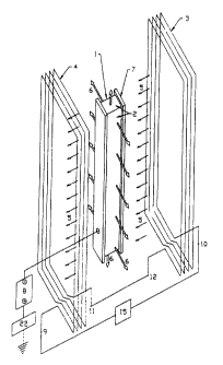
Fig. 1 shows a simplified view of a magnetron cathode of the
present invention, comprising a substantially rectangular bar 1
with evaporable surface 2 wrapping around the periphery (including
corresponding opposite surfaces not visible in the perspective
view). Electromagnet coils 3 and 4 are disposed coaxially on each
side of cathode bar 1, their common axis parallel to all segments
of evaporable surface 2 and perpendicular to the long axis of the
bar. Small arrows 5 indicate the direction of the magnetic field
along the common coil axis due to current in the direction shown in
coils 3 and 4. The magnetic field along the axis is parallel to
all of evaporable surface 2 and perpendicular to the long axis of
cathode bar 1. Large arrows 6 indicate the principle directions of
vapor emission, which are substantially perpendicular to evaporable
surface 2, at various points around the cathode. For long cathodes
most of the vapor is emitted in two opposite directions per-
pendicular to the long axis of the cathode. Side elements 7 are
disposed adjacent to the non-evaporable sides of cathode bar 1,
which are the two parallel sides of bar 1 which are not part of
evaporable surface 2. Side elements 7 provide lateral confinement
of the plasma discharge at the edges of the evaporable surface, and
may comprise insulating or metallic plates as described below.
Conventional means for mounting, water cooling, shielding, and
electrical insulation may be utilized but are not shown. Cathode
1 is connected to the negative output of a plasma discharge power
supply 8, which may have appropriate characteristics for either arc
or sputtering discharges as described above. The positive terminal
of discharge supply 8 is connected to an anode 22, which may be a
11
CA 02254677 1998-11-25
grounded metal vacuum chamber or a separate structure which may or
may not be grounded.
Current in coils 3 and 4 may be provided by a coil power
supply 15 connected to coil terminals 9 and 10, with coil terminals
11 and 12 connected together. Alternatively (connections not
shown) the coil current may be provided by connecting coil terminal
9 to ground (or to an anode), and terminal 10 to the positive
output of discharge supply 8 (or vice versa), such that the
discharge current from discharge supply 8 also flows through coils
3 and 4. The coils 3 and 4 may be shielded from the discharge
plasma within or outside the vacuum chamber, or may be exposed to
the plasma within the vacuum chamber and thus form part of the
anode of the discharge. In another embodiment (connections not
shown), coils 3 and 4 are located within the vacuum chamber,
exposed to the plasma, and function as the only anode for the
discharge. In this embodiment, coil terminals 10 and 11 are
connected together, as are coil terminals 9 and 12 which are also
connected to the positive output of discharge supply 8. Electron
current collected by the anode therefore flows through both coils
3 and 4 to the positive terminal of discharge supply 8, generating
a magnetic field as indicated by small arrows 5. In this
configuration it may be desirable to ground coils 3 and 4
temporarily to facilitate initiation of the plasma discharge.
Fig. 2 shows a plot of the magnetic flux lines in a cross-
section (top view) of the cathode and coil arrangement of Fig. 1.
The direction of current flow is into the page in wires 3a and 4a
and out of the page in wires 3b and 4b. A cathode may generally be
operated with coil current flowing in either direction. Small
arrows 5 show the direction of the flux lines at the indicated
locations, corresponding to small arrows 5 in Fig. 1. The flux
lines in the regions 13 above evaporable surface 2 are
substantially parallel to surface 2, but are slightly convexly
12
CA 02254677 1998-11-25
arched due to the additional presence of magnetic field components
perpendicular to surface 2 as described below. The degree of
arching, and therefore the degree of magnetic lateral confinement
of the plasma discharge, can be controlled by size and location of
the coils, with larger more distant coils causing less arching and
smaller less distant coils causing more arching. The coil current
and number of coil turns may be chosen to provide the desired field
strength, according to the means of providing the coil current.
For example a current of 250 amps in-4--turn coils 3 and 4 of Fig.
2 will provide a parallel field component of about 40 Gauss at the
cathode surface, while a current of 20 amps in coils 3 and 4 having
500 turns each would provide a parallel field component of about
400 Gauss.
Side elements 7 may project a distance d of zero or greater
above (outward from) the surface, and may have side walls 14 facing
evaporable surface 2 which are inclined at an angle a of zero or
greater away from the perpendicular to the surface. Various
embodiments of side elements 7 may be employed within the scope of
the present invention. In one preferred embodiment of an arc
evaporation cathode, insulating plates (for example boron nitride)
are placed in contact with both edges of evaporable surface 2 to
prevent movement of an arc spot off evaporable surface 2. The
insulating plates may be flush with the evaporable surface (i.e.
d=0) or may extend a distance of several millimeters or more
outward from the evaporable surface. In another preferred
embodiment of an arc cathode, side elements 7 comprise metallic
plates in contact with both edges of evaporable surface 2. The
plates may comprise for example the cathode material itself,
another metal such as stainless steel, a magnetically permeable
material or preferably a material with higher arc discharge voltage
than the evaporable surface, and may preferably project a distance
d of several millimeters or more above the evaporable surface
13
CA 02254677 1998-11-25
around its entire periphery. Materials having high arc discharge
voltages include refractory metals such as molybdenum and tantalum.
The, projecting element 7 may also preferably have a wall angle a of
20 degrees or more, thus forming acute angles between the magnetic
field lines and the projecting side walls of elements 7. An arc
spot which moves onto the angled side wall will therefore tend to
be pushed back down onto the evaporable surface by interaction with
the magnetic field. In another embodiment of an arc cathode,
electrically grounded or isolated metallic plates are disposed
adjacent to both edges at a distance of around 1 mm or greater, in
order to extinguish arcs moving off evaporable surface 2 or to
repel the arc spot by means of eddy currents. One preferred
embodiment of a sputtering cathode employs metallic side elements
7 which project a distance d of several millimeters or more above
the evaporable surface, having walls which may be inclined at an
angle a from zero to around 70 degrees. The side elements may be
composed of the cathode material or another electrically conductive
material. The projecting side walls serve in this case to prevent
diffusion of the sputtering plasma along the magnetic field lines
away from evaporable surface 2. In another preferred embodiment of
a sputtering cathode, side elements 7 may comprise metallic plates
disposed adjacent to both edges at a distance of around 1 mm or
greater and projecting a distance d of several millimeters or more
above the evaporable surface. The plates may be electrically
floating or biased at a voltage intermediate between cathode and
anode, and may comprise part of the cathode housing or magnetic
pole structures. The projecting side walls serve also in this case
to prevent diffusion of the sputtering plasma along the magnetic
field lines away from evaporable surface 2.
In addition to or instead of lateral confinement means
employing side elements 7, lateral confinement of a sputtering or
arc discharge may be accomplished by means of a closed-loop,
14
CA 02254677 1998-11-25
convexly-arched magnetic tunnel wrapping around the periphery of
the rectangular bar above the evaporable surface. The arched shape
of the magnetic tunnel can be described as due to the addition of
perpendicular magnetic field components to the previously described
parallel component, producing a net convex curvature of the field
in the region above the evaporable surface. The perpendicular
field components produce lateral forces on the sputtering plasma or
arc spot, pushing it toward the center of the erosion track from
both sides. Stronger perpendicular components result in more field
curvature and stronger lateral confinement forces. Formation of a
narrow erosion groove in the cathode may be prevented by utilizing
a magnetic field which changes curvature from convex above the
cathode surface to concave below the surface (within the cathode
material) as described in U.S. Patent 4,892,633 (Welty) and shown
in Figs. 7 and 8 of the present invention. The perpendicular
magnetic field components may be generated by appropriate
configuration and placement of the same magnetic field generating
means which produce the magnetic field component parallel to the
evaporable surface. Commercial finite-element magnetic modeling
programs such as Maxwell from Ansoft Corporation of Pittsburgh, PA
provide suitable capability for cathode design purposes.
Fig. 3 shows a cross-sectional view of a preferred embodiment
of the present invention, in which replaceable cathode elements 1
having evaporable surfaces 2 are mounted around the periphery of
mounting block 15, comprising a rectangular bar with water cooling
channels 16 and o-ring seals 17. Side elements 7 having side walls
14 are disposed around both edges of evaporable surface 2, and
project a distance of at least around 2 mm and more preferably
around 5 to 10 mm above the evaporable surface around its entire
periphery. Elements 7 may also preferably have a wall angle (a in
Figure 1-B) of 20 degrees or more away from the perpendicular. In
the case of an arc cathode, side elements 7 may comprise for
CA 02254677 1998-11-25
example the cathode material itself, another metal, an insulating
material, a magnetically permeable material, or preferably a metal
having an arc discharge voltage higher than that of the evaporable
surface material. In the case of a sputtering cathode, side
elements 7 may be comprise the same material as the cathode or
another electrically conductive material. Cathode elements 1 are
held on mounting block 15 by clamps 23 using screws not shown.
Magnetic field generating means comprise side magnets 18 and center
magnet 19, side magnetically permeable pole pieces 20 and center
permeable pole pieces 21. Magnets 18 and 19 have magnetization
oriented parallel to evaporable surfaces 2 in the directions
indicated by the arrows within the magnet blocks. An anode 22 is
disposed adjacent to the edges of evaporable surface 2. Conven-
tional mounting, connection, shielding, and insulator means may be
used but are not shown.
Fig. 4 shows a perspective view of the magnets and pole pieces
of the embodiment of Fig. 3. Side magnets 18 are mounted around
the edges of side permeable pole pieces 20. Center magnets 19 are
mounted between segments of center permeable pole pieces 21, which
are disposed between side pole pieces 20. Magnets 18 and 19 and
pole pieces 20 and 21 together form a magnetic circuit having a
pole gap between the magnets 18 on opposite sides of evaporable
surface 2 shown in Fig. 3. Magnetic flux is generated across the
gap between opposing faces of magnets 18 as shown in Fig. 7.
Cathode elements 1 are located within the pole gap such that flux
generated in the pole gap passes over all of evaporable surfaces 2,
including the ends, providing a magnetic field component parallel
to evaporable surfaces 2 around the entire periphery of the
cathode. Center pole pieces 21 pass through the center of the
mounting block 15 (Fig. 3) and magnetically connect the two side
pole pieces 20, in order to complete the magnetic circuit and
provide a "return path" for magnetic flux. Magnets 18 provide most
16
CA 02254677 1998-11-25
of the magnetic field within the pole gap, while magnets 19 serve
mainly to influence the shape of the field within the gap. Center
pole pieces 21 may be fabricated in multiple separate sections
along the length of the cathode, as shown in Fig. 4, in order to
preserve the mechanical integrity of mounting block 15.
Fig. 5 shows a cross-sectional view of another preferred
embodiment of the present invention, in which the cathode comprises
a rectangular bar 1 having evaporable surface 2. Mounting blocks
15 having water channels 16 and o-ring seals 17 are disposed on the
non-evaporable sides of bar 1 and are clamped in tight contact by
conventional means not shown to provide cathode cooling. Side
elements 7 are disposed around the edges of evaporable surface 2,
and may comprise insulating or metallic materials as discussed for
Figs. 2 and 3. Magnetic field generating means comprise side
magnets 18 and center magnetically permeable pole pieces 21.
Magnets 18 have magnetization oriented perpendicular to evaporable
surfaces 2 as indicated by the arrows. Center pole pieces 21 may be
fabricated in multiple separate sections along the length of the
cathode, as shown in Fig. 6, in order to preserve the mechanical
integrity of cathode bar 1. An anode 22 is disposed along the
edges and extending outward from evaporable surface 2. Conven-
tional mounting, connection, shielding, and insulator means may be
used but are not shown.
Fig. 6 shows a perspective view of the magnets and pole pieces
of the embodiment of Fig. 5. Magnets 18 are mounted around the
periphery of the center pole piece 21 on opposite sides of the
cathode bar 1. Magnets 28, having magnetization perpendicular to
the evaporable surface on the end of the cathode bar, are disposed
on the pole pieces 21 at the ends of the cathode, in order to
generate a parallel field component over the evaporable surface at
the ends. Magnets 18 and pole pieces 21 together form a magnetic
circuit having a pole gap between magnets 18 on opposite sides of
17
CA 02254677 1998-11-25
evaporable surface 2. Magnetic flux is generated across the gap
between opposing faces of magnets 18 as shown in Fig. 8. Cathode
bar 1 is located within the pole gap such that flux generated in
the pole gap passes over all of evaporable surface 2, including the
ends, providing a magnetic field component parallel to evaporable
surfaces 2 around the entire periphery of the cathode. Center pole
pieces 21 pass through the center of cathode bar 1 and magnetically
connect the magnets 18 on opposite sides of the cathode, in order
to complete the magnetic circuit and provide a "return path" for
magnetic flux.
Figs. 7 and 8 show plots representing cross-sections of the
magnetic field generated by the magnet and pole structure of Figs.
3 and 5, respectively. Referring now to both Figs. 7 and 8, the
magnetic flux lines in the region 30 near evaporable surface 2 are
predominantly parallel to evaporable surface 2 and perpendicular to
the long axis of the cathode. The magnetic field is convexly
arched in the region 31 above the evaporable surface and concavely
arched in the region 32 below the evaporable surface within the
cathode bulk, in order to provide magnetic lateral confinement of
the plasma discharge above the evaporable surface while preventing
formation of a narrow erosion groove as the cathode material is
vaporized. The strength of the magnetic field may be controlled by
selection of the magnet material and of the thickness "t" of the
magnet (in the direction of magnetization). For example in the
configurations of both Figs. 7 and 8, ceramic grade-8 magnets 3 mm
thick will provide a parallel field component of around 50 Gauss
across an evaporable surface width of 7.5 cm, while neodymium
grade-35 magnets 10 mm thick will provide a parallel field
component of around 500 Gauss. Magnets of these types can be
obtained, for example, from Magnet Sales, Inc. of Los Angeles, CA.
Fig. 9 shows an arrangement for coating deposition or ion
implantation in which a multiplicity of substrate mounting spindles
18
CA 02254677 1998-11-25
36 are disposed around a central cathode 35 of the present
invention. Mounting spindles 36 may comprise means for holding a
number of smaller substrates to be coated or implanted. Arrows 6
indicate the directions of vapor emission from cathode 35. The
entire array of substrates may rotate around the cathode 35 to
achieve uniform coverage. Individual substrates 36 may also rotate
around their own axes to improve uniformity or increase the
substrate mounting area. Various other arrangements are possible
within the scope of the present invention. For example, Fig. 10
shows an arrangement for coating deposition or ion implantation in
which two streams of substrates 36 move linearly past a central
cathode 35 of the present invention. The substrates may move
continuously or intermittently, and may also rotate on their own
axes to improve uniformity or increase the substrate mounting area.
In another embodiment, a cathode and anode assembly such as that
shown in Figure 3 may be used to coat the inside of a pipe or tube,
with relative rotation between the cathode and pipe to obtain
uniform coverage. Lower macroparticle content can thereby be
obtained in arc-deposited internal pipe coatings than can be
obtained using a cylindrical arc cathode.
Multiple cathodes of the same or different evaporable
materials may be placed inside the substrate array in order to
increase the total vaporization rate or to deposit or implant mixed
alloys or multi-layered structures. The cathode of the present
invention is well suited to side-by-side arrangements since the
evaporable surface can be made much narrower than is possible for
a planar magnetron cathode, thereby providing a more compact cath-
ode assembly and more overlap of the emission distributions. It
may be advantageous to use both sputtering and arc cathodes in a
multiple cathode system. For example a sputtered coating can be
deposited first, then an arc evaporated coating, or vice-versa. In
the case of alloying certain materials it may be desirable to
19
CA 02254677 2002-03-13
operate one cathode (e. g. aluminum) as a sputtering cathode
to avoid excessive macroparticle generation, while operating
the other (e.g. titanium) as an arc evaporation cathode to
obtain the benefits of enhanced ionization and reactivity.
Side-by-side mounting of multiple cathodes may require
adjustment of the magnetic pole strengths or orientation to
compensate for magnetic interaction between cathodes.
In the case of arc evaporation, the manner of
attaching the power cables to the cathode can have an effect
on the cathode erosion uniformity. Arc currents of several
hundred amperes within the cables and the cathode itself
generate magnetic fields which can affect the movement of
the arc spots on the evaporable surface. For arc
evaporation cathodes of the present invention it is
generally desirable to make power connections symmetrically
on both non-evaporable sides of the cathode. The power
cables may be routed symmetrically along the sides of the
cathode in order to obtain maximum cancellation of the self-
magnetic fields.
While particular embodiments of the present
invention have been shown and described, various
modifications thereof will be apparent to those skilled in
the art. Therefore, it is not intended that the invention
be limited to the disclosed embodiments. The term
"substantially rectangular" in referring to the shape of a
cross section of a cathode of the present invention is
understood to include variations in overall shape due to
mounting means, insulators, etc. and variations in the
profile of the evaporable surface which may be desirable to
improve lateral confinement of the plasma discharge or
influence the erosion or emission distribution.