Note: Descriptions are shown in the official language in which they were submitted.
CA 02254770 1998-11-12
WO 97/44567 PCT/GB97/01357
-1-
Downhole tool
This invention relates to a downhole flow monitoring tool, and concerrts in
particular
a tool for the downhole injection of one or more tracer or marker materials
into a flowing
multiphase fluid in a hydrocarbon well, for subsequent detection downstream of
the
injection point.
When a well, specifically an oil or gas well, has been completed and is
yielding the
desired product it is necessary to monitor the well's perfonmance to ensure
that it is behaving
as expected. In particular, it is desirable to measure the rate at which the
well's products - in
an oil well, for example, these would be oil, water, gas or a combination,
even a mixture, of
all three - are flowing along the borehole and up to the surface, and it is
generally desirable
to monitor the flow velocities actually down the well itself rather than
merely when they
reach the surface. Many types of method and apparatus have been proposed for
this
purpose; two typical such involve firstly the use of a mechanical "spinner"
and secondly the
use of tracer or marker materials. In the spinner case a wireline- supported
tool carrying a
small propeller- (or turbine-) driven dynamo is placed in the flowing fluid so
that the
propeller is turned around by it, and the dynamo's output indicates the flow
velocity. In the
tracer/marker case there is used an injector/detector tool, by which a
suitable material - for
example, a detectable chemical or a radioactive substance - is injected into
the fluid, and its
arrival time at a downstream detector station is noted, giving the flow
velocity by a simple
distance-over-time calculation. Spinners work satisfactorily in borehole
sections that are
vertical, but not nearly so effectively in sections which are horizontal - it
is common these
days for a well to include a section driven horizontally through the
underground geological
formation delivering the sought-after product - for in such a section the well
fluid is liable to
be stratified into individual component layers (with the heaviest, such as
water/brine, on the
bottom, the lightest, such as methane gas, on the top, and any others, such as
oil, in the
middle), and these layers are not necessarily flowing at the same speed. A
spinner placed in
the borehole across two differently-flowing layers is therefore likely to
output a signal which
is at best some sort of average, and is at worst quite meaningless. For fluid
flow velocity
measurement in horizontal wellbore sections, therefore, it has been suggested
that there
should be employed tracer/marker materials and the appropriate
injector/detector tools, and it
is with this that the present invention is concerned.
CA 02254770 1998-11-12
WO 97/44567 PCT/GB97/01357
-2-
There are many specific techniques utilising tracer/marker materials. For
example, in
a group of methods that might be referred to as "nuclear" there can be
involved: radioactive
substances, and detecting the radiation they emit; activatable substances,
that on exposure to
a radiation source become unstable, and detecting their decay products;
neutron-absorbing
substances, and detecting the fall in received neutrons from a source as the
tracer passes by;
and X-ray-absorbing (that is, dense) substances, and detecting the way they
modify the
radiation received from some appropriate X-ray source. Numerous techniques and
materials
have been previously proposed in the literature for use in monitoring flows in
oil wells, and
reference is made to the patents and technical literature.
However, regardless of what specific technique is employed, there remains the
problem of measuring the flow velocity of the desired component of the
wellbore fluid, and
in part this is usually done simply by preparing the tracer/marker material
that is significantly
more soluble - or, at least, more miscible - in the chosen component than it
is in the other(s).
Thus, for monitoring a well's water/brine output the selected material is
conveniently
formulated as an aqueous solution, while an oil-miscible composition is used
if it is the
well's oil output that needs to be observed. All that is then left is for the
tracer/marker
composition to be inserted into the well fluid at the selected part of the
horizontal section in
such a way that it ends up in the desired component layer, and in the past
this has been
achieved merely by introducing the composition into the fluid somewhere across
the
borehole, and allowing it to migrate to its intended target. Thus, if injected
into the bottom,
aqueous layer, an aqueous tracer composition naturally stays there, while an
oil-soluble
composition is immiscible with (and lighter than) this bottom water layer and
might be
expected to rise up to and through the water/oil interface and so into the
targeted oil layer.
And, in theory, vice versa; injected into the upper, oil layer the oil-
miscible composition
stays there, while the water-based one migrates across the interface into the
bottom, aqueous
layer.
Unfortunately, and despite what seems to be accepted wisdom in the published
literature about the theory of this technique, the Applicants have discovered
through
laboratory experiments that in practice the passage of the composition through
the interface
is in either case extremely difficult if not actually impossible, and that the
assumptions made
in this field about tracer migration in a miscible phase are simply, and
unexpectedly, wrong.
More specifically, either the passage of the composition through the interface
is subject to
some indetenninate delay or, and worse, the composition, having passed through
the
interface, is poorly (if at all) absorbed into the component. This is
especially so if the
composition materials can themselves become particulate and coated with the
wrong (in this
case, aqueous) layer component; as will be appreciated, such a delay, or such
a poor
CA 02254770 1998-11-12
WO 97/44567 PCT/GB97/01357
-3-
absorption, causes either the flight time or the concentration of the tracer
between injection
and detection points to be unrepresentative of the speed or volume of the
selected layer, and
thus the estimated flow velocities/rates of the respective fluid phases can be
substantially
incorrect. The problem is discussed further hereinafter with reference to
Figures 4a-h of the
accompanying Drawings.
As might be expected, it is not nonnally acceptable to monitor the flow
velocity of
only one component layer in a horizontal borehole section, for much useful
information can
be gained by effectively simultaneously looking at all the layers. Nor is
convenient to make
use of tracer-injection equipment that has to be orientated one way for
injecting the tracer
composition into one layer and then re-oriented before it can be used to
inject a second tracer
composition into a second layer. It is therefore highly desirable to employ
means for
introducing the relevant tracer compositions that can, without intermediate re-
orientation, in
fact inject two (or more) different layers with the relevant tracer
compositions, and even be
able to inject them simultaneously. It is such a flow-monitoring, injection
tool that the
invention proposes. More specifically, the invention suggests an injection
tool that
comprises a plurality of spaced ejection ports (from which the relevant tracer
composition
can be ejected so as to be injected into the relevant chosen component layer),
together with
orientation means whereby in use the orientation of the tool can be so
adjusted that the ports
are so disposed as concurrently to lie each within the appropriate layer.
Naturally, each port
will be operatively connectable to a source of the relevant tracer composition
from which
will in use be supplied the amount to be injected; most conveniently the
source will be the
combination of a reservoir and a syringe-like device (which latter can draw a
suitable amount
of the composition from the reservoir and then drive it to, and eject it from,
the associated
port into the chosen layer).
In one aspect, therefore, the invention provides a downhole flow-monitoring
tool for
monitoring the flow of fluid within a borehole, the tool including an injector
for injecting a
tracer or marker material into a flowing fluid in a first borehole region, and
means for detecting
said tracer or marker material in the flowing fluid at a second downstream
borehole region,
wherein said injector comprises:
a main body positionable in use within the borehole;
first means for injecting the material through an ejection port positioned in
use at one
side circumferentially of the borehole; and
second means for injecting the material through another ejection port
positioned in use at the opposite side circumferentially of the borehole.
.. ........ .___.. .__........____.--r _-._..._.~....,_......~
.................._.__......__._~._..-...................,P.. .......
__......_....,..-._.__,___.__....._.._._.._..___~._.._..__ .__ . . .
CA 02254770 1998-11-12
WO 97/44567 PCT/GB97/01357
-4-
In an alternative version of this same aspect, the invention may be viewed as
an
injection tool, for use in the monitoring of the flow velocities of the
stratified components in
a horizontal section of a well such as an oil well, which injection tool is
for injecting into
each of the chosen component layers a tracer/marker composition, and which
tool includes a
plurality of spaced ejection ports, at least one for each chosen component
layer, together
with orientation means whereby in use the orientation of the tool can be so
adjusted that the
ports are so disposed as to lie each within the appropriate layer, and wherein
each port is
operatively connectable to a source of the relevant tracer composition.
Though it may of course have other applications, the injection tool of the
invention is
primarily for use in the monitoring of the flow velocities of the stratified
components in a
horizontal section of a well. As noted above, the well may be any sort of
well, but will
typically be an oil well, the well fluid components thus being mainly water
(usually in the
form of brine), oil and gas (mostly methane). Moreover, although the injection
tool is
described as being of use in the monitoring, and measurement, of flow
velocities, it can
have other uses. For example, given a knowledge of the initial injected volume
and of the
diffusivity (k) of the tracer composition within the chosen component layer,
then the actual
volumetric flow rate of the layer can be determined from a knowledge of the
concentration of
the tracer at the point of detection (and this concentration can itself be
determined from a
measurement of the amplitude of the detected signal).
The invention relates to monitoring the flow velocities of the stratified
components in
a horizontal section of a well; as will be fully understood by those versed in
the Art, such a
"horizontal" section may but will usually not be exactly horizontal, and the
invention applies
in essence to any wellbore section that has the fluid flowing in it in
stratified, or layered,
form. Such layered flow can be experienced when the borehole is deviated at an
angle - up
or down - of five, ten or even more degrees to the horizontal.
Depending on the nature of the tool string of which the injection tool of the
invention
is a part, the tool may be a "centred" tool - one designed to be positioned
roughly axially in
the borehole - or it may be an eccentred tool - one designed to be positioned
eccentrically in
the well alongside the well casing/borehole wall (and most conveniently
sitting on the
bottom of the borehole).
The invention provides an injection tool for injecting into each of the chosen
component layers a tracer/marker composition. The composition, and the nature
of the tracer
CA 02254770 1998-11-12
WO 97/44567 PCT/GB97/01357
-5-
or marker material within it, may take any of the forms used or proposed for
use in the Art -
a number of these have been noted hereinbefore - and no more need be said
about them here.
The tool of the invention includes a plurality of spaced ejection ports out of
which
the appropriate tracer/marker material can be ejected for injection into the
relevant wellbore
fluid component layer. There are obviously at least as many ports as there are
layers that are
required to be monitored - thus, a minimum of two (for two layers), and
perhaps three or
even more - and they are spaced so that, when the tool is properly orientated
within the
borehole, each port is in the layer to which it relates, and thus that the
tracer/marker
composition ejected therefrom is injected directly into the correct layer. The
actual spacing
will, of course, be appropriate to the particular circumstances - thus, the
diameter of the
borehole, and whether the tool is centred or eccentred. For a typical 7 inch
(17.5cm) oil
well completion pipe, for instance, the spacing of the ports in an eccentred
injection tool
might be around 5 inches (12cm), while for a centred tool the spacing might be
2.5in (6cm).
The injection tool includes at least one ejection port for each chosen
component
layer. It may be desirable - so as to permit a greater amount of tracer/marker
composition to
be injected in one go - for each layer to have two, or even more, associated
ports. In one
preferred two-phase fluid oil well embodiment there are two ports associated
with the water
layer but only one for the oil layer.
Some or all of the ejection ports are preferably fitted with two-way relief
valves to
prevent a backflow of borehole fluid into the ports (unless this is required
for pressure
relief), and to prevent leakage of tracer material.
The invention provides an injection tool which includes a plurality of spaced
ejection
ports. Of course, the tool has a body, and the ports are in effect apertures
in the body (and,
as stated, each of these is operatively connected to a source of the relevant
tracer/marker
composition). However, while each port might be merely an aperture in the
body, it is
preferred, to keep the body small (as discussed below) and yet have the
several ports
appropriately spaced, if the or each port for at least one of the chosen
layers be provided
with an extension in the form of a narrow, elongate tube, through which tube
the
composition is delivered to the free end at which it is ejected from the tube
and so injected
into the layer; in such a case it is in effect the free end, or nozzle, of the
tube that constitutes
the ejection port, and it is the free end that is spaced from the other
port(s). It is, of course,
possible for the port(s) for each of the chosen layers to incorporate such an
extension tube,
and in one preferred embodiment such is the case.
CA 02254770 1998-11-12
WO 97/44567 PCT/GB97/01357
-6-
The injection tool of the invention has, as just noted, a body in which
apertures
constitute the ports through which the trace/marker material is to be ejected,
which apertures
may have tube-like extensions. This body may be in one or more portions, each
portion
carrying one or more of the port-defining apertures, as required. Indeed, in
one particularly-
preferred embodiment of the invention the body is in two very similar -
substantially
identical - portions each of which carries one of two tubular-extension-
utilising ports from
the free, nozzle, end of which the tracer material is injected into the
relevant fluid component
layer (as just described above), and the two portions are arranged
sequentially along the tool
and each so orientated relative to the other that its tube-extended port has
the free end located
in the layer of interest. Moreover, and as shown in the embodiment discussed
further
hereinafter in connection with the accompanying Drawings, it is very
convenient if each
portion be, in fact, a "single- bodied" injection tool of the invention - with
two ports one of
which has an operative tubular extension reaching into the component layer of
interest and
the other of which is an unextended aperture in the body and is actually
blocked off (and so
is inoperative) - the two tools being effectively identical (save for the
choice of port to be
utilised) and arranged front-to-back linearly to form the whole tool. Having
two "identical"
body portions in this manner tends to facilitate the supply of the relevant
tracer/marker
material from a reservoir thereof via a suitable pump mechanism to the port
(the use of
reservoirs and pumps is described further hereinafter). The tool of the
invention may, for
convenience, be discussed herein as though it had a single body portion, but
it will be
understood that where appropriate the remarks are also intended to refer to
tools with two
(or more) body portions.
As intimated above, the tool - and specifically the body of the tool - should
be small
(in cross-section; it can be quite long, however) in relation to the size of
the borehole, and
this is so that it does not significantly occlude, or block, the borehole (for
that would
artificially reduce the flow of the various well fluids, and so result in
"false" readings).
The invention's tool includes orientation means whereby in use the orientation
of the
tool can be so adjusted that the ports are disposed such that each lies within
the appropriate
layer. There are two such orientations that need to be taken into account; one
is the spatial
orientation - the ports need to be positioned appropriately across the width
of the borehole -
while the other orientation is angular - for a well fluid stratified into
horizontal layers the
ports naturally need to be disposed vertically, so that one is in a lower
stratum while another
is above it, in an upper stratum. The first of these - spatial orientation -
may conveniently be
achieved by providing the tool with spacer elements that in use effectively
stretch across the
borehole, and by locating the ports relative to those spacer elements such
that when in
position the ports will necessarily be appropriately disposed across the
borehole. The spacer
CA 02254770 1998-11-12
WO 97/44567 PCT/GB97/01357
-7-
elements can be made adjustable, so that they permit the tool to fit inside
differently-sized
boreholes (and to pass through minor constrictions in a borehole), and the
location of each
port relative to the spacer elements can be adjustable, to allow for use in
wells where the
component layers are of different depths. A very convenient form of spacer
element is a
bow-shaped spring - a bow spring - attached at one end to the tool and
extending out and
away therefrom and then curving back toward the tool (where it may either be
completely
free or it may be coupled to the tool in such a way as to permit it to move
axially relative to
the tool); the flexibility of the spring, coupled with one end of it being
axially free (and
floating axially relative to the tool) means that it will adjust it.self
automatically to place the
tool within a roughly predetermined position across the borehole regardless
(again within
limits) of the actual width of the borehole. With such a bow spring spacer
element it is
advantageous to employ a port with a tubular extension, as mentioned above,
and to arrange
for that extension to run up the bow spring from the fixed end to a point
therealong -
conveniently at the midpoint of the bow - at which the tube's nozzle, and thus
the effective
ejection port aperture, is located. Then, as the bow spring flexes in and out
to adjust to
different borehole widths, so the ejection port simultaneously moves in and
out to stay
located within the relevant chosen layer.
With one such bow-spring-plus-port-extension spacer element the tool will be
an
eccentred tool, with its body and one port disposed alongside the borehole
wall and with a
second port positioned spaced therefrom and adjacent the centre of the bow.
However, in
another preferred embodiment of the invention there are at least two such bow
springs,
extending in opposite directions, each with an associated port extension tube
and nozzle;
such a tool would be a centred tool, with its body lying in use near the axis
of the borehole,
and its two ports disposed one near each opposed wall. If it is necessary to
centre the body
more definitively then it would be possible to have three (or more) bow
springs so disposed
angularly relative to each other that they provide a more forceful
centralisation (three
bow springs would be at 120 to each other, four at 90 , and so on).
So far as concerns the angular orientation of the tool and its ports, it is
possible to
utilise some sort of driven, "motorised" orientation system, perhaps
associated with a
detector device for determining when the tool is correctly orientated (or when
one or other
port is actually in the relevant chosen layer). However, a simpler, and
presently-preferred,
way of achieving the necessary orientation is simply to weight the tool
eccentrically, so that
it orientates itself suitably under gravity (and as appropriate it might be
the injection tool
itself that is so weighted or it might be some other part of the associated
tool string to which
the injection tool is fixed in orientation). In such a preferred embodiment
using a single
bow spring spacer element the tool has an elongate rod-like body to which the
bow spring
CA 02254770 1998-11-12
WO 97/44567 PCT/GB97/01357
-8-
is mounted by way of a loose collar, or "shuttle", disposed around the body.
Each end of
the bow spring may be mounted to the body by such a shuttle, and to locate the
spring
lengthwise of the body it is convenient to have one such shuttle keyed to the
body,
preventing axial movement while permitting angular movement, while the other
shuttle can
move freely in both senses. In a case where there is one bow spring carrying
one ejection
port extension and the other port(s) is in the tool body, the weight of the
body will in use
cause it to lie on the bottom surface of the horizontal borehole section, in
the bottom
component layer, while the bow spring projects up into the upper component
layers; the
rotatable nature of the bow spring mounting (the shuttle) means that the tool
will always
adopt this orientation no matter how it may first be disposed within the
borehole. However,
in a centred tool case using two or more bow springs disposed around the tool,
and where
the tool's orientation is fixed relative to some other part of the complete
tool string, there
may be no need for such relatively complicated shuttle mountings, and instead
the spring
may be fixedly secured (at one end, at least) to the tool body.
In the injection tool of the invention each ejection port is operatively
connectable to a
source of the relevant tracer composition - that is to say, each port has
leading thereto a
channel, conduit, tube or other suitable passageway along which the relevant
tracer/marker
composition can be fed to the port for ejection therefrom, and this channel
can be connected
to a reservoir for that composition, in which reservoir the composition can be
stored ready
for use, and from which it can be delivered - under pump pressure, say - to
the channel and
thus to the port. Each channel, or the like, may take any suitable form; in a
preferred
embodiment it is a simple conduit fashioned within the body of the tool.
In the cases where the tool is associated with a spacer element in the form of
a
shuttle-mounted bow spring, and there is a ejection port with an extension
tube running
along the bow spring, it will clearly be necessary to arrange suitable means
whereby the
relevant tracer/marker composition can be fed from the "stationary" ejection
port in the body
of the tool to the moveable in-board end of the extension tube. This can be
effected using
conventional means, such as surface arcuate channel portions in one of the
body and shuttle
associated with radial conduits in the other, and with sealing 0-rings to
prevent leakage of
the composition between body and shuttle, and an embodiment of this is
discussed further
hereinafter with reference to the accompanying Drawings.
As just noted, each ejection port is operatively connectable to a source of
the relevant
tracer composition from which it can be delivered - under pump pressure, say -
to the port.
Because the accuracy of this type of tracer/marker flow monitoring technique
depends to a
considerable extent on providing for the detection and measurement a short,
"sharp",
CA 02254770 1998-11-12
WO 97/44567 PCT/GB97/01357
-9-
well-defined pulse of the tracer/marker material, it is highly desirable to
eject the material
into the flowing well fluids in one burst, and a fast-acting mechanism is
necessary to achieve
this. For use with the tool of the invention, then, it is very much preferred
to employ for
each ejection port a spring-loaded syringe both as the (small) primary
tracer/marker reservoir
and as the pump, which syringe, once loaded with composition, can be triggered
to drive the
composition to, and eject it from, the relevant port in the desired one short
burst. However,
since it may be desired to make a number of sequential flow measurements at
any one site,
or even to make some measurements at one site and then to move the tool to,
and take
measurements at, another, and because it may be difficult in a controlled
manner to arrange
for only a part of the syringe's contents to be squirted out each time, it is
highly desirable to
provide for each port a larger secondary, or storage, reservoir from which the
syringe can be
re-filled for each subsequent use. And to enable the syringe to withdraw
composition from
this storage reservoir it is convenient to provide the syringe with a
motorised or spring-
poweredplunger and suitable one-way-valved connections to the reservoir and to
the ejection
port. In a particularly preferred embodiment the amount of composition drawn
into the
syringe may be varied in accordance with the circumstances, so as to deliver a
larger or
smaller burst into the chosen layer as may be required.
The injection tool of the invention is for use in a flow monitoring system in
which a
suitable composition is injected into the chosen layer of the flowing well
fluid and then
detected, by one means or another, at some distance downstream from the
injection point.
The detection means may form an integral part of the injection tool - with an
elongate tool the
ejection may take place at one end, the detection at the other - but apart
from noting that
detection may be accomplished in any way appropriate to the tracer/marker
materials being
used the matter need not be discussed further here.
The downhole injection tool of the invention is intended to be used in a
downhole flow-monitoring system for a deviated or horizontal well where the
well fluid is
stratified, so that a suitable composition can be injected into the chosen
layer(s) of the
flowing fluid and then detected, by suitable equipment, at some distance
downstream from
the injection point. In another aspect, therefore, the invention provides a
method of
measuring downhole the flow velocities of selected phases of a multiphase
fluid in a
deviated or horizontal borehole, in which method a downhole flow monitoring
tool of the
invention is positioned within a deviated or horizontal portion of the
borehole and employed
both to inject a first tracer or marker material in a first fluid phase
located adjacent the bottom
circumferential side of said borehole, said first material being selected to
be a material
CA 02254770 2006-08-21
72424-58
- 10 -
miscible in said first fluid phase, and also - and without
re-orientation - to inject a second tracer or marker
material in a second fluid phase located adjacent the upper
circumferential side of said borehole, said second material
being selected to be a material miscible in said second
fluid phase, and in which method there is then measured the
time taken for each tracer/marker material to pass a known
distance along the borehole, this time/distance information
then being utilised to calculate the required flow
velocities.
Thus, in a broad aspect, the invention provides a
downhole flow-monitoring tool for monitoring the flow of
multiphase fluid within a borehole, the tool including an
injector for injecting tracer or marker material through at
least two separated ports into a flowing fluid in a first
borehole region, and means for detecting said tracer or
marker material in the flowing fluid at a second downstream
borehole region, wherein at least one port of said at least
two separated ports is mounted on a structure extendable
away from the main body of the tool.
In another aspect, the invention provides method
of monitoring the flow of multiphase fluid within a
borehole, comprising the steps of injecting tracer or marker
material through at least two separated ports into a flowing
fluid in a first borehole region; and detecting said tracer
or marker material in the flowing fluid at a second
downstream borehole region, wherein the step of injecting
said tracer or marker material includes the steps of
positioning said ports into different phases of said flow
and injecting tracer or marker material directly into said
different phases.
CA 02254770 1998-11-12
WO 97/44567 PCT/GB97/01357
-11-
Various embodiments of the invention are now described, though by way of
illustration only, with reference to the accompanying Drawings in which:
Figure 1 shows in cross-section a complete injection tool according to the
invention;
Figures 2A-D show details of the tool of Figure 1(Figures 2A-C fit together,
end to end, to
show the whole tool, while Figure 2D shows details of one of the shuttles
employed); and
Figures 3A&B show two different alternative tools of the invention.
Figures 4a-h relate not to the tool of the invention but instead to results of
laboratory
experiments of a marker material being injected through a water/oil interface.
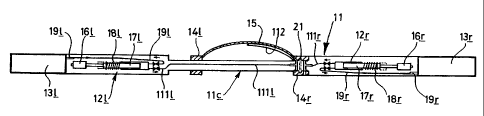
The injection tool shown in Figures 1& 2 has an elongate, rod-like body (11)
with
an injection pump, or syringe (121, 12r) and associated tracer/marker
composition storage
reservoir (131,13r) at either end (the individual components are shown in more
detail in
Figures 2A-D). In the centre is a narrower portion (l le) carrying two collar-
like
shuttles (141,14r); one of these, 14r on the right as viewed, is able to
rotate around the rod
but is keyed (21 in Figures 2B & D) to prevent it moving axially, while the
other, 141 on
the left, may both rotate and move axially. Attached at each end to one of the
two
shuttles 14 is a bow spring (15).
Each syringe 12 has an associated motor (161,16r), which drives the plunger
(171,17r) against a spring (181,18r) that can, when the syringe is triggered
(by means not
shown) rapidly drive the plunger 17 down to empty the syringe of its contents.
The
motor 16 withdraws the plunger 17, causing the syringe to fill itself by
drawing
tracer/marker composition along a one-way valved conduit (191,19r) from the
associated
reservoir 13, while when triggered the spring-driven plunger forces the
syringe's contents
out along another one-way valved conduit (1111,111 r); the left (as viewed)
one of these
extends through the central tool section I lc to near the other end. Each such
output
conduit 111 feeds composition to a port (221, 22r: see Figure 2D) linked to a
corresponding port/passage (231, 23r) in the right-hand, axially-fixed shuttle
14r (this is
sealed to the rod l le by a number of 0-rings 24); one of these port/passages
23 - in this
case, 23r - is open directly to the borehole space and fluid surrounding the
injection tool,
while the other, 231, is fitted with an extension tube (112) that follows the
curve of the
bow spring 15 up to the mid point thereof, and then ends in a valved nozzle
(not shown
separately).
CA 02254770 1998-11-12
WO 97/44567 PCT/GB97/01357
-12-
The injection tool embodiment shown in part in Figure 3A is in many ways
similar to
that of Figures 1 and 2, save that it is a centred tool, and has four bow
springs (three -
15t,15b, 15s - are visible), spaced around the body. Two of them - 15t,15b -
each have an
ejection port extension tube (112t,112b), so that in use the tool sits with
its body (31) roughly
coaxial of the borehole, one bow spring and tube 15,112 at the top and the
other at the
bottom.
The alternative tool of Figure 3B is a tool having its body in two distinct
but
substantially identical portions. Each portion utilises a centered tool
assembly (351, 35r)
much like that of Figure 3A, but each portion has a single tubular port
extension
arm (361, 36r). In fact, each portion 35 has two ports, but only one is shown;
in one case
one of those ports has the extension arm 36, and the other port is blanked
off, while in the
other case it is the other of the ports that has the extension arm 36 (and
"the one" port is
blanked off).
The two portions 35 are joined front-to-back to make a linear whole, and are
associated
with control packages, tracer material reservoirs and metering chambers, and
solenoid-operated
valves, not shown separately.
Figures 4a - 4h show what happens when an oil-based marker is injected through
a
water/oil interface into the oil phase.
As illustrated in Figures 4a - 4h, an oil based marker (50) is forcibly
injected from
within the water phase (51) shown at the bottom of the tank (52), upwards into
the oil
phase. The coloured marker fluid used has a kerosene base that is identical to
the oil phase
and totally miscible therewith. Furthermore, the marker fluid is not miscible
in the water
phase, and can therefore be expected, in conventional thinking, to migrate
quickly and
disperse in the oil phase. However, as can be seen this is not what happens at
all.
The Figures show a time-lapsed sequence of what happens to the marker
material.
After injection into the oil phase, shown progressively in Figures 4a-c, the
marker breaks up
into many balloon-like bubbles. These have been found to be coated with a thin
film of
water from water/oil interface, and this unexpected result causes the marker
bubbles to repel
instead of mix with the surrounding oil phase. In addition, the thin films of
water forming
the bubbles can have a high surface tension which can physically pull the
bubbles down
towards the water/oil interface, and further prevent any mixing with the oil
phase. The
CA 02254770 1998-11-12
WO 97/44567 PCT/GB97/01357
- 13-
water/oil interface (53) acts like a strong elastic membrane that permits a
limited
encroachment of the marker material breaking through the interface, but has
sufficient
strength to capture the marker bubbles and eject them back into the
originating phase.
These experimental results indicate that any injected marker material that is
forced to
pass through a two-phase interface may well not mix properly with the intended
phase, and
therefore will not measure correctly the velocity of either the selected phase
or the total fluid.
The problems identified by these results are solved by the apparatus and
method described
hereinabove.