Note: Descriptions are shown in the official language in which they were submitted.
CA 02254907 1998-11-13
WO 97/42909 PCT/GB97/01282
1
1 "Methods and Apparatus for the Detection of Dental
2 Caries"
3
4 This invention relates to methods and apparatus for use
in detecting dental caries ( i.e. dental decay, or
6 "caries" or "carious lesions") by electrical and/or
7 electronic means.
8
9 Caries is defined as the progressive decay of tooth or
bone, and dental caries is the most common ailment
11 known world wide. Dental caries can be treated by
12 either removing the decayed material in the tooth and
13 filling the resultant space with a dental amalgam, or
14 in severe cases, by removal of the entire tooth.
16 The early diagnosis of dental caries is of utmost
17 importance to any subsequent treatment since by the
18 time pain is felt due to decay of the tooth, the
19 treatment required to restore the tooth may be
extensive and in some cases, the tooth may be lost.
21
22 Historically, the diagnosis of dental caries has been
23 primarily visual, frequently accompanied by tactile
24 examination using a mechanical probe. The patient may
only seek an examination by a dental surgeon when in
CA 02254907 1998-11-13
WO 97/42909 PCT/GB97/01282
2
1 pain due to the caries and the surgeon must then
2 identify the offending tooth by visual examination
3 and/or by use of a mechanical probe which causes
4 discomfort or pain in the decayed tooth. This
experience is painful and distressing for the patient
6 and acts as a disincentive to regular visits to the
7 surgeon for routine examinations. In addition, the
8 diagnosis of caries at this late stage of decay reduces
9 the available options for treatment.
11 The diagnosis of caries by conventional techniques has
12 become increasingly difficult. This is a result of
13 several factors, including apparent changes in the
14 morphology and in the rate of progress and distribution
of carious lesions, as well as the inaccessibility of
16 approximal (mutually contacting) dental surfaces and
17 the complicated anatomy of pit and fissure sites on the
18 occlusal (biting) surfaces.
19
An additional problem with conventional techniques is
21 that decay on the approximal surface of the tooth
22 resulting from plaque on the inter dental spaces may
23 not be detected by simply prodding the tooth, since the
24 approximal surfaces may not be reached by the probe.
The limitations of conventional visual, tactile and
26 radiographic diagnosis are well recognised. Decay may
27 progress to an advanced stage on both occlusal and
28 approximal sites without being detected until
29 substantial tooth destruction has occurred.
31 In response to these generally unsatisfactory and
32 unreliable methods of diagnosis attempts have been made
33 to develop electrical/electronic means for the
34 diagnosis of caries.
36 Electronic Caries Detectors (ECD's) generally comprise
CA 02254907 2006-02-17
3
1 a probe having a first, probe electrode which is placed in contact
2 with the tooth to be tested, and a second, counter electrode
3 separate from the probe which is placed in contact with another
4 part of the body of the patient in order to complete an electrical
circuit connecting the two electrodes. The second electrode may be
6 held by the patient or may be placed in contact against the gingiva
7 (gum) or oral mucosa (inside cheek). An alternating electric
8 current of fixed frequency is passed through the tooth and the
9 resistance to this is measured. This electrical resistance has been
found to correlate approximately inversely with the extent of
11 caries in the tooth. The technique may involve measurement at a
12 single point on the surface of the tooth, or the use of an
13 electrically conductive paste, providing a measurement for the
14 surface as a whole.
16 The configuration of conventional designs of ECD probes are such
17 that they cannot contact approximal tooth surfaces, and therefore
18 cannot detect approximal caries which does not extend to the
19 occlusal or free smooth surfaces of the tooth. No satisfactory
means to detect such approximal caries is currently known, although
21 the problem of approximal caries has been prevalent for many years.
22 Hitherto, the most accurate method of diagnosing approximal caries
23 has been bitewing radiography, but this method is only about 30%
24 accurate and requires the use of ionising radiation.
26 Even where good electrical contact can be established between the
27 probe electrode and the relevant site, conventional ECD apparatus
28 is of limited usefulness in the detection of caries.
29
It is desirable to provide, among others, improved apparatus and
31 methods for the electrical/electronic diagnosis of dental caries of
32 all types; electrical/electronic probes for the detection of
CA 02254907 2006-02-17
4
1 approximal caries; and improved electrical/electronic probes for
2 the assessment of the occlusal and free smooth surfaces of the
3 tooth.
4
In accordance with a first aspect of the invention there is
6 provided a method for use in the detection of dental caries,
7 comprising the steps of placing at least one probe electrode in
8 electrical contact with a surface of a patient's tooth, placing a
9 second electrode in electrical contact with another part of the
body of the patient, passing an alternating electrical current
11 between the probe and second electrodes, and measuring the
12 electrical impedance between the electrodes to the electrical
13 current; wherein the frequency of the alternating current is varied
14 over a predetermined frequency range and the electrical impedance
is measured for a plurality of frequency values within the range;
16 wherein the impedance measurement and corresponding frequencies are
17 analyzed by means of an alternating current impedance spectroscopy
18 technique (ACIST) and a diagnosis of the tooth is based on the form
19 of the impedance spectrum obtained thereby; and wherein the probe
electrode comprises an array of miniature electrodes, enabling
21 simultaneous or sequential impedance measurements to be made at
22 multiple sites on one or more surfaces of the tooth.
23
24 In the preferred embodiment of the invention, the impedance
measurement and corresponding frequencies are analyzed by means of
26 an alternating current impedance spectroscopy technique (ACIST) and
27 a diagnosis of the tooth is based on the form of the impedance
28 spectrum obtained thereby. The measurement frequencies are
29 preferably in the range up to 500 kHz. Most preferably, the lower
and upper frequencies in the range and the number of frequencies at
31 which impedance measurements are made are selected on the basis of
32 the type, size and configuration of the probe electrode(s), the
CA 02254907 2006-02-17
1 specific tooth surface(s) and/or site(s) being contacted and
2 whether or not the tooth has previously been restored (filled).
3
4 The probe electrode may comprise an array of miniature electrodes,
5 enabling simultaneous or sequential impedance measurements to be
6 made at multiple sites on one or more surfaces of the tooth.
7
8 Preferred forms of apparatus for use in the method, including
9 preferred types of probe electrodes for approximal and other tooth
surfaces, are as defined below in relation to further aspects of
11 the invention and as described more fully in the following
12 description of embodiments of the various aspects of the invention.
13
14 In accordance with a second aspect of the invention, there is
provided apparatus for use in the detection of dental caries, the
16 apparatus comprising: at least one probe electrode adapted to be
17 placed in electrical contact with a surface of a patient's tooth, a
18 second electrode adapted to be placed in electrical contact with
19 another part of the body of the patient, an alternating current
source adapted for passing an alternating electrical current
21 between the probe and second electrodes, and impedance measurement
22 means for measuring the electrical impedance between the electrodes
23 to the electrical current; wherein the alternating current source
24 is a variable frequency alternating current source whereby the
frequency of the alternating current applied to the tooth may be
26 varied over a predetermined frequency range and the impedance
27 measurement means is adapted to measure impedances corresponding to
28 a plurality of frequency values within the range; wherein the
29 apparatus further includes data processing means adapted to analyze
the impedance measurements and corresponding frequencies by means
31 of an alternating current impedance spectroscopy technique (ACIST)
CA 02254907 2006-02-17
5a
1 in order to generate an impedance spectrum; and wherein the probe
2 electrode comprises an array of miniature electrodes, enabling
3 simultaneous or sequential impedance measurements to be made at
4 multiple sites on one or more surfaces of the tooth.
6 In accordance with a third aspect of the invention,
CA 02254907 1998-11-13
WO 97/42909 PCT/GB97/01282
6
1 there is provided a probe electrode device for use in
2 the electrical/electronic detection of dental caries,
3 comprising a substrate of electrically insulating
4 material, and at least one electrode of electrically
conductive material disposed on at least one surface of
6 said substrate.
7
8 Preferably, said substrate comprises a generally
9 planar, flexible, hydrophobic material, preferably
PTFE, and most preferably Goretex. Where the device is
11 intended for examination of approximal tooth surfaces,
12 said substrate is sufficiently thin to fit between the
13 approximal surfaces of adjoining teeth.
14
In certain embodiments of the third aspect of the
16 invention, said at least one electrode comprises a
17 layer of electrically conductive material applied to
18 said substrate, preferably carbon impregnated PTFE, and
19 most preferably carbon impregnated Goretex. In other
embodiments, the electrodes comprise corrosion-
21 resistant metal or other conductive material, such as
22 carbon. The substrate may further include a strip of
23 absorbent or hydrophobic material extending along at
24 least one edge thereof.
26 In certain preferred embodiments, the probe device
27 includes a plurality of electrodes located on said
28 substrate. Said plurality of electrodes are preferably
29 embedded in and project from said substrate. The
electrodes may take the form of bands or disks, and are
31 adapted for connection to the measurement circuit of a
32 caries detection system either individually,
33 collectively or in predetermined groups. The substrate
34 is preferably connected to a holder/contact means,
adapted to provide electrical connection between said
36 electrodes and a measurement circuit. In one
CA 02254907 1998-11-13
WO 97/42909 PCT/GB97/01282
7
1 embodiment, the substrate is tapered in transverse
2 cross section and includes a tapered core portion of
3 compressible material, electrodes being provided on
4 both opposite surfaces of said substrate.
6 Preferably, said plurality of electrodes are arranged
7 in an array on said substrate. Most preferably, the
8 width or diameter of said electrodes and the spacing
9 between adjacent electrodes is in the range 0.5 m to
200 m.
11
12 In accordance with a fourth aspect of the invention,
13 there is provided a dental caries detection system
14 comprising apparatus in accordance with the second
aspect of the invention and at least one probe
16 electrode device in accordance with the third aspect of
17 the invention. The system is preferably adapted to
18 perform dental caries detection in accordance with the
19 method of the first aspect of the invention.
21 Other aspects and preferred features of the invention
22 are discussed in the following description of examples
23 of the invention.
24
Embodiments of the invention will now be described, by
26 way of example only, with reference to the accompanying
27 drawings, in which:
28
29 Fig. 1 is a schematic block diagram illustrating a
caries detection system embodying the invention;
31
32 Fig. 2 is a graph showing plots of impedance
33 values at varying frequencies for three sample
34 teeth having different degrees of decay;
36 Fig. 3 is a plan view of one side of an approximal
CA 02254907 1998-11-13
WO 97/42909 PCT/GB97/01282
8
1 probe electrode for use in a caries detection
2 system such as that of Fig. 1, embodying a further
3 aspect of the invention;
4
Fig. 4 is an end view of the electrode of Fig. 3;
6
7 Figs. 5(a) and 5(b) are, respectively, end and
8 front views of a first embodiment of a microprobe
9 array embodying a further aspect of the invention;
11 Figs. 6(a) and 6(b) are, respectively, end and
12 front views of a second embodiment of a microprobe
13 array embodying said further aspect of the
14 invention;
16 Fig. 7 is a front view of a third embodiment of a
17 microprobe array embodying said further aspect of
18 the invention;
19
Figs. 8(a) and 8(b) are, respectively, end and
21 front views of a seventh embodiment of a
22 microprobe array embodying said further aspect of
23 the invention, configured for use on occlusal
24 tooth surfaces;
26 Fig. 9 is a front view of an eighth embodiment of
27 a microprobe array embodying said further aspect
28 of the invention, configured for use on occlusal
29 tooth surfaces;
31 Fig. 10 is a front view of a ninth embodiment of a
32 microprobe array embodying said further aspect of
33 the invention, configured for use on occlusal
34 tooth surfaces;
36 Fig. 11 is an end view of a tenth embodiment of a
CA 02254907 1998-11-13
WO 97/42909 PCT/GB97/01282
9
1 microprobe array embodying said further aspect of
2 the invention, configured for use on occlusal
3 tooth surfaces;
4
Fig. 12 is a schematic isometric view illustrating
6 a first holder/contact unit for use with the
7 microprobe arrays of Figs. 5 to 13.
8
9 Fig. 13 is a schematic isometric view illustrating
a second holder/contact unit for use with the
11 microprobe arrays of Figs. 5 to 13.
12
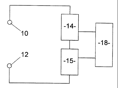
13 Referring now to the drawings, a basic caries detection
14 system in accordance with the invention comprises a
first "probe" electrode (or array of electrodes, as
16 shall be discussed further below) 10, a second
17 "counter" electrode 12, a variable frequency
18 alternating current (a.c.) source 14 and impedance
19 measurement means 16, connected in series as shown with
an open circuit between the probe and counter
21 electrodes, and data processing and control means 18
22 connected to receive data from the impedance
23 measurement means 16 and to control the operation of
24 the a.c. source 14.
26 The probe electrode 10 is adapted to be placed in
27 electrical contact with the surface of the tooth which
28 is to be examined and the counter electrode 12 is
29 adapted to be placed in electrical contact with another
part of the body of the patient, as discussed above,
31 completing the circuit so that the impedance
32 measurement means 16 measures the impedance between the
33 two electrodes.
34
in use of the apparatus, the a.c. source 14 applies a
36 predetermined voltage across the electrodes 10,12 so
CA 02254907 1998-11-13
WO 97/42909 PCT/GB97/01282
1 that the current flowing in the circuit varies with the
2 impedance between the electrodes. This impedance is
3 measured by the impedance measurement means 16. During
4 examination of a tooth, the frequency of the a.c.
5 source 14 is varied over a predetermined range and
6 impedance measurements are recorded for a number of
7 frequencies within the range.
8
9 The impedance measurements are analyzed by the data
10 processing means. In accordance with the preferred
11 embodiment of the invention the analysis comprises an
12 a.c. impedance spectroscopy technique (ACIST).
13 Suitably, the measurement frequencies are in the range
14 up to 500 kHz. The lower and upper frequencies in the
range and the number of frequencies at which impedance
16 measurements are made may be selected on the basis of
17 the type, size and configuration of the probe
18 electrode(s), the specific tooth surface(s) and/or
19 site(s) being contacted and whether or not the tooth
has previously been restored.
21
22 The use of ACIST in detecting dental decay was tested
23 using a sample of teeth consisting of 26 unrestored,
24 extracted premolar teeth, with varying degrees of
carious lesions in their approximal surfaces. The
26 individual approximal surfaces were assigned to one of
27 three groups on the basis of their direct visual
28 appearance: sound (S) if no visible sign of caries was
29 apparent; lesion (L) where white or brown spot lesions
(indicative of demineralization due to caries) were
31 evident with no detectable loss of surface enamel; and
32 cavitated (C) if there was a carious lesion with an
33 area where there was obvious loss of surface enamel.
34 For each group, ten tooth surfaces were measured.
Subsequent to measurement, the teeth were hemisectioned
36 and serially sectioned to validate the visual
CA 02254907 1998-11-13
WO 97/42909 PCT/GB97/01282
11
1 categorisation of the teeth and to determine the true
2 extent of any caries in enamel or dentine.
3
4 For these experimental purposes, the a.c. impedance
measurements were carried out with the teeth placed in
6 a custom-built perspex chamber. Each tooth was
7 positioned in such a way that one of its approximal
8 surfaces was facing an aperture in the chamber, through
9 which the probe electrode, consisting of a stainless
steel rod with a suitable electrically conducting
11 material (discussed further below) at the tip, could be
12 inserted to touch the surface of the tooth. A platinum
13 counter electrode was used, the circuit being
14 completed using K-Y lubricating jelly (Johnson &
Johnson) as a conducting gel between the counter
16 electrode and the root of the tooth. Each test tooth
17 was held in wax at the base of the chamber.
18
19 Measurements were carried out using a computer-
controlled Solartron Frequency Response Analyzer (FRA)
21 1255 connected to the cell via either a Solartron
22 Potentiostat 1286 or EG&G 181 amplifier. The latter
23 configuration was used for high impedance (>1MSZ)
24 measurements. Impedance measurements were carried out
over a wide range of frequencies, typically from 300kHz
26 to 1 Hz. At least six measurements were carried out on
27 each of the teeth to establish reproducibility of the
28 results.
29
The results of the measurements of a representative
31 tooth from each of the three categories S, L and C are
32 shown in the graph of Fig. 2, where the impedance
33 measured at each frequency for each of the three
34 representative tooth samples are plotted on the complex
plane. The values of the imaginary impedance Z" are
36 plotted against the real impedance Z'. Three impedance
CA 02254907 1998-11-13
WO 97/42909 PCT/GB97/01282
12
1 "spectra" were thus obtained for the three sample
2 teeth, labelled S, L and C on the graph. The plot for
3 the group C tooth is enlarged in the inset, for
4 clarity. The distance of each point from the origin of
the graph represents the magnitude of the impedance and
6 the angle subtended with the x-axis represents the
7 phase angle 0.
8
9 The electrical response of any material can be
represented by an equivalent electrical circuit
11 consisting only of resistors and capacitors. In this
12 particular case the equivalent circuit consists of four
13 components: two resistors and two capacitors. The
14 component representing the bulk resistance is connected
in parallel with the capacitor representing the bulk
16 capacitance. The second resistance is connected in
17 parallel with a constant phase element, the impedance
18 of which is given by Acu'n-jBcv"n, where A, B and n are
19 constants and w = 2nf, where f is the frequency of the
sinusoidally varying voltage.
21
22 The complex impedance data were analyzed using the
23 computer program "Z Plot" (Solartron Instruments). A
24 series of initial experiments were carried out to
establish the contribution of the electrodes, gel,
26 contacts and leads. These were found to be negligible
27 in comparison with the impedance of the teeth.
28
29 The equivalent circuit derived for use in the
experiments was fitted to the measurement data using a
31 non-linear least-squares procedure. In Fig. 2, the
32 solid lines represent the best fit obtained, and the
33 dots represent the data. The scale of the differences
34 in the in the electrical responses of the teeth in each
of the three histological categories S, L and C is
36 readily apparent.
CA 02254907 1998-11-13
WO 97/42909 PCT/GB97/01282
13
1 The mean values (with standard deviations) for the
2 total resistances in MQ (the sum of the two resistances
3 in the equivalent circuit), for each of the three
4 groups were:
Sound, S 53.47 (+/- 11.2)
6 Lesion, L 3.73 (+/- 2.58)
7 Cavity, C 0.31 (+/- 0.18).
8 The impedance values for each of the three groups
9 differ by an order of magnitude from the other two
groups. The S group had values in the range 37-77 MS2,
11 compared with L group values in the range 0.9-10 MSZ and
12 C group values in the range 76-559 kS2.
13
14 Following the ACIST measurements, the approximal
aspects of the teeth that were measured were
16 photographed before hemisection of the teeth in the
17 mesio-distal plane. The hemisections were examined
18 under X2.5 and X10 magnification in a stereomicroscope,
19 using reflected light, to assess the extent of caries.
Photographs were taken of each hemisection and the
21 teeth subsequently serially sectioned to produce 120 m-
22 thick sections, which were then viewed microscopically
23 and scored for caries, and assigned to one of the
24 groups S, L and C for comparison with the results of
the ACIST analysis.
26
27 It can be seen from Fig. 2 that the impedance
28 measurements for each of the three classes of teeth, S,
29 L and C, fall into three quite distinct groups which
corresponded exactly with the results of the subsequent
31 microscopic examination of the teeth. Reproducibility
32 of these results was excellent.
33
34 This study shows that the "total" resistance of teeth
as derived from a.c. impedance spectroscopy
36 measurements is highly correlated with the presence and
CA 02254907 1998-11-13
WO 97/42909 PCT/GB97/01282
14
1 extent of decay in the teeth, as validated by
2 histological examination.
3
4 The results show that the accuracy of the a.c impedance
spectroscopy technique in this study was effectively
6 100%, in terms of both sensitivity and specificity.
7
8 The experimental technique used in this "in vitro"
9 study can be transferred with minimal modification to
"in vivo" use, thereby providing the basis for a system
11 for clinical use having substantially higher accuracy
12 than current methods of caries diagnosis.
13
14 The necessary a.c. source, impedance measurement means
and control and data processing means may be integrated
16 and/or packaged in any one of a number of ways for
17 clinical use. It will be understood that the block
18 diagram of Fig. 1 is primarily for illustrative
19 purposes and does not necessarily reflect the physical
arrangement of the components of a practical, clinical
21 system.
22
23 Besides the basic methodology, hardware and software
24 required to apply an ACIST approach to caries
detection, the other main requirement for a clinical
26 system is the provision of probe electrodes configured
27 and optimised for "in vivo" use in order to enable
28 examination of all of the relevant approximal, occlusal
29 and free smooth surfaces of the teeth.
31 There will now be described a preferred embodiment of
32 an approximal probe electrode in accordance with a
33 further aspect of the invention.
34
Referring now to Figs. 3 and 4, a probe electrode 110
36 for use in examining the approximal surfaces of teeth
CA 02254907 1998-11-13
WO 97/42909 PCT/GB97/01282
1 in an electrical/electronic caries detection system
2 comprises an electrically insulating substrate 120
3 having an electrically conductive portion superimposed
4 on at least a portion thereof and adapted to contact
5 the approximal surface of a tooth when the substrate 20
6 is inserted between adjacent teeth.
7
8 In this example, the substrate 120 has conductive
9 portions 122 on both sides thereof, allowing the
10 approximal surfaces of two adjacent teeth to be
11 examined without the need to remove and re-orient the
12 substrate. In this example also, the substrate 120 is
13 a generally elongate rectangle, and the conductive
14 portions 122 comprise strips of conductive material
15 extending along the length of the substrate 120 closer
16 to one lateral edge thereof than to the other, but
17 spaced from both lateral edges. The conductive
18 portions 122 on either side of the substrate 120 are
19 electrically isolated from one another.
21 In order to be suitable for clinical use, the electrode
22 must be sufficiently thin, strong and flexible to be
23 capable of being drawn between tightly abutting
24 approximal surfaces of adjacent teeth, and must be
hydrophobic and capable of being made electrically
26 conductive at selected, specific locations.
27
28 A particularly preferred material meeting these
29 criteria is polytetrafluoroethylene (PTFE), which is
electrically insulating but which is capable of being
31 selectively impregnated with conductive material. Most
32 preferably, the PTFE comprises a material such as that
33 manufactured and sold under the Trade Mark "Goretex".
34
In the illustrated example, the substrate 120 is formed
36 from electrically insulating PTFE material, while the
CA 02254907 1998-11-13
WO 97/42909 PCT/GB97/01282
16
1 conductive strips 122 comprise layers of carbon
2 impregnated PTFE secured to the substrate 120. The
3 electrode is non-conductive in the area which will
4 contact the gingiva, in use, (i.e. the lower lateral
edge). The hydrophobic properties of PTFE aid
6 electrical isolation of the conductive electrode area
7 from oral fluids.
8
9 The probe electrode 110 in accordance with this aspect
of the invention thus provides a means of making
11 isolated electrical contact with the approximal surface
12 of a single tooth, while providing electrical
13 insulation between the electrode and the gum adjacent
14 the tooth being tested. The probe electrode 110 may
either be connected to a suitable, electrically
16 conducting lead forming part of the circuit of Fig. 1,
17 or else an electrode forming part of said circuit may
18 be placed temporarily in contact with that part of the
19 relevant conductive portion 122 of the probe electrode
110 which protrudes from between the teeth when
21 measurements are to be taken, the counter electrode
22 being held by the patient or being placed in contact
23 with another portion of the patient's body distant from
24 the tooth.
26 The configuration of the probe electrode 110 is such
27 that electrical current is prevented from passing
28 through adjacent teeth or through the gum, since the
29 conductive material 122 of the electrode 110 is
restricted to discrete areas on the substrate 120 and
31 is insulated from the gum by the lower portion 124 of
32 the non-conductive substrate.
33
34 Carbon impregnated PTFE was used, attached to the end
of a stainless steel rod, for establishing electrical
36 contact with the surfaces of the teeth in the
CA 02254907 1998-11-13
WO 97/42909 PCT/GB97/01282
17
1 experimental tests described above in relation to Figs.
2 1 and 2. Initial "in vivo" studies using an electrode
3 in accordance with Fig. 3 produced results consistent
4 with the "in vitro" study, indicating that the required
electrical isolation of the conductive portions of the
6 probe electrode from surfaces and fluids other than the
7 surface under test is achieved in an "in vivo"
8 situation.
9
Variations of the embodiment shown in Figs. 3 and 4
11 might include the conductive portions 122 being
12 restricted to specific areas, such as elliptical areas,
13 on the substrate, with extensions of the conductive
14 material leading to the upper lateral edge of the
substrate 120 to allow connection to the circuit of the
16 detection apparatus. Also, a fluid absorbing material
17 might be attached along the lower lateral edge of the
18 substrate 120 to absorb oral fluids and assist in the
19 electrical isolation of the conductive portions 122.
21 There will now be described embodiments of a further
22 probe arrangement in accordance with still another
23 aspect of the invention.
24
This further aspect of the invention relates to the use
26 of a probe device having a number of small probe
27 electrodes ("microelectrodes" or "microprobes")
28 arranged in an array. The microprobes may be formed
29 from various possible conducting materials, such as
metals which are corrosion resistant in the oral
31 environment (e.g. platinum or gold) or carbon. The
32 microprobes may take the form of wires, strips (bands)
33 or disks, sealed or embedded in an electrically
34 insulating carrier material. The microelectrodes may
have a diameter in the range l m to 100 m. The
36 carrier material may be rigid (e.g. glass) or may be
CA 02254907 1998-11-13
WO 97/42909 PCT/GB97/01282
18
1 formed from a thin, flexible material which can be
2 brought into intimate contact with the surface of the
3 teeth. Alternatively, the microprobes may have
4 submicrometer dimensions (approximately 106 active
electrodes per square centimeter).
6
7 Microprobe arrays of this type may be used as the probe
8 of an electrical/electronic caries detection system
9 such as that of Fig. 1. The system may include
computer software which transforms the results of the
11 a.c. impedance measurements of the teeth into
12 information regarding their health and internal
13 structure.
14
The use of such arrays facilitates the analysis of the
16 health and structure of the teeth with great precision
17 (on the micrometer scale) taking into consideration the
18 depth and the surface of the tooth being studied. This
19 allows a three-dimensional (depth-surface) profile of
the tooth to be obtained, thereby providing a map of
21 the dental caries within the tooth and facilitating the
22 provision of a very precise diagnosis of the health
23 status of the tooth in a painless, safe and rapid
24 manner (a few minutes per patient).
26 The arrays may include varying numbers of electrodes
27 and may be configured for application to occlusal,
28 approximal and free smooth surfaces of tooth crowns, as
29 well as root surfaces, of both restored and unrestored
teeth. The counter electrode may be placed on the
31 unrestored or restored tooth and/or a restored portion
32 of a restored tooth being measured, or on the oral soft
33 tissues, or may be held in the hand of the patient.
34
Embodiments of such devices will be described with
36 reference to Figs. 5 13. It will be understood that
CA 02254907 1998-11-13
WO 97/42909 PCT/GB97/01282
19
1 these drawings are for illustrative purposes only, and
2 the size, numbers and spacings of the microprobes may
3 vary considerably from the illustrations. In
4 particular, the microprobes may be substantially
smaller in size, larger in number and more closely
6 spaced. Typically, the width or diameter of the
7 microprobes and of the spaces between adjacent
8 microprobes might be in the range 0.5 - 200 m.
9
The array design will vary according to the site being
11 contacted and the material being used for the
12 microelectrodes.
13
14 Fig. 5 shows an example of a microprobe array 210
configured particularly for use on approximal tooth
16 surfaces. In this example the microelectrodes 212
17 comprise narrow bands embedded in a carrier body 214 of
18 non-conducting material, such as resin. The
19 microprobes 212 project from the "front" (tooth-
contacting) surface of the carrier 214, typically by 1
21 - l00 m, and extend to its upper edge for connection to
22 the circuit of the detection apparatus.
23
24 The carrier 214 is generally planar and rectangular in
shape, typically having a width of 10mm and a thickness
26 in the range 75-120 m. The length of the carrier 214
27 is sufficient to accommodate the required microprobe
28 array with spaces at either end to facilitate handling.
29 The array of microprobes 212 might typically extend
along a length of 5 - 10mm of the central portion of
31 the carrier 214. A strip of absorbent or hydrophobic
32 material 216 extends along the lower edge of the
33 carrier 214 to assist in isolating the microprobe array
34 from the gum and oral fluids and also to act as a
physical compressor. Preferably, this is a strip of
36 PTFE (Goretex), which may be up to 50 m in thickness
CA 02254907 1998-11-13
WO 97/42909 PCT/GB97/01282
1 and 1 - 2mm in width.
2
3 Figs. 6 and 7 show alternative embodiments in which the
4 microprobes comprise disks 218, 220 respectively. In
5 Fig. 6, each microprobe 218 has an individual conductor
6 222 connecting it to the top edge of the carrier 214.
7 In Fig. 7, the microprobes 220 are connected to the top
8 edge of the carrier 214 in groups by conductors 224.
9
10 Microprobe arrays for use on free smooth tooth surfaces
11 can be generally similar to the approximal devices
12 shown in Figs. 5 to 6, the overall dimensions of the
13 carrier and of the actual array being varied to suit
14 the surfaces in question.
16 Figs. 8 to 11 illustrate embodiments of microprobe
17 arrays configured for use on occlusal tooth surfaces.
18
19 In the example of Fig. 8, the device 310 comprises a
non-conductive carrier 314 carrying an array of
21 projecting band-type microelectrodes 312 similar to
22 those of Fig. 5. The carrier 314 is typically about
23 40 m in thickness and is connected along its top edge
24 to a holder/contact-scanner unit 316 (described further
below). A tapered block 318 of compressible material
26 (preferably PTFE/Goretex) is secured to the carrier 314
27 on the opposite side thereof from the microprobes 312.
28
29 Figs. 9 and 10 show variations of occlusal devices
similar to the variants of Figs. 6 and 7. In Fig. 9,
31 disk electrodes 320 are connected individually to
32 conductors 322. In Fig. 10, groups of disk electrodes
33 324 are connected in groups by conductors 326.
34
Fig. 11 shows a further example of an occlusal device
36 410. In this case the non-conductive carrier 414 is
CA 02254907 1998-11-13
WO 97/42909 PCT/GB97/01282
21
1 tapered and has a central, tapered core 418 of
2 compressible material (preferably PTFE/Goretex). The
3 carrier 414 suitably tapers from about 80 m to about
4 30 m. Projecting microelectrodes 412 are located on
both surfaces of the carrier 414, so as to contact the
6 occlusal surfaces of upper and lower teeth
7 simultaneously. The microelectrodes 412 may be of the
8 band or disk type. In the latter case they may be
9 arranged and connected as shown in either Fig. 9 or
Fig. 10. The upper edge of the carrier 414 is again
11 connected to a holder/scanner unit 416.
12
13 The holder/scanner units of Figs. 8 to 11 serve to
14 facilitate handling of the devices and also provide
means for connecting the various microelectrodes/
16 conductors to the measurement circuit of the detection
17 system. The devices may be configured such that all of
18 the microelectrodes in the array are connected
19 individually, or in groups or all in common. Where
connected individually in groups, holder/scanner unit
21 and/or the measurement circuit may include means for
22 connecting each electrode or group into the circuit in
23 turn for taking impedance measurements (i.e. for
24 "scanning" the electrodes. Fig. 12 illustrates a
holder/contact unit 516 in which a common "busbar" 520
26 is arranged to contact all of the microprobes/
27 conductors of the array. Fig. 13 illustrates a
28 holder/contact unit 616 in which individual conductors
29 620 are provided for connection to individual
microelectrodes/conductors or groups of
31 microelectrodes/conductors of the array. The choice of
32 individual, group or common connection of the array can
33 be made depending upon the type of information which is
34 required from the examination.
36 For occlusal devices, the band or disk electrodes may
CA 02254907 1998-11-13
WO 97/42909 PCT/GB97/01282
22
1 be arranged in various configurations to facilitate
2 electrical contact with the enamel of the pit and
3 fissure pattern of the occlusal surfaces (which varies
4 between individual teeth). The size of these occlusal
arrays may vary in width, depth and thickness.
6
7 The computer software which processes the measurement
8 data from the microprobe arrays may transform the
9 impedance measurements into information showing
analysis of the electrical resistance and capacitance
11 of the measured tooth structure. This in turn is
12 transformed, by means of an experimentally derived
13 equivalent circuit, into information about the extent
14 of mineralisation and surface integrity of the tooth
structure, as previously described. The actual
16 equivalent circuits derived will depend on the size and
17 configuration of the microprobe arrays used. By means
18 of the use of experimentally derived results for the
19 electrical properties of sound and diseased tooth
tissue at a sub-micrometer level, a computer program
21 based on a developed three-dimensional model of tooth
22 tissue at various specific sites may be used to
23 transform the a.c. impedance data obtained during an
24 examination into a three-dimensional (depth-surface )
profile of the tooth surface being measured. This may
26 provide a map of the dental caries within the tooth,
27 facilitating the provision of a very precise diagnosis
28 of the health status of the tooth.
29
The system of Fig. 1 is advantageously used with one or
31 more of the types of probe electrode device described
32 with reference to Figs. 3 to 13, providing a caries
33 detection system which may provide a reliable,
34 repeatable and accurate examination of all occlusal,
approximal and free smooth surfaces of teeth "in vivo".
36
CA 02254907 1998-11-13
WO 97/42909 PCT/GB97/01282
23
1 Improvements and modifications may be introduced
2 without departing from the scope of the invention.
3