Note: Descriptions are shown in the official language in which they were submitted.
CA 022~443 1998-12-07
REMOTE POWER INLET BOX FOR AN AUXILIARY POWER SUPPLY SYSTEM
BACKGROUND AND SUMMARY OF THE INVENTION
This invention relates to a system for providing auxiliary power to the
electrical system of a building in the event of a power outage or the like, and more particu-
5 larly to a power inlet box for use in such a system.
In an auxiliary power supply system, a remote power generator is intercon-
nected with a power inlet box which is typically mounted to the exterior of a building. The
power inlet box is in turn interconnected with a manual transfer switching arrangement,
which is connected to the main electrical panel or load center of the building. A cord is
10 interconnected with the power outlet of the generator and with a power inlet receptacle
associated with the power inlet box, for providing power from the generator through the
power inlet box to the manual transfer panel and ultimately to the main electrical panel, in
order to supply power to certain circuits of the building in the event of a power outage or
the like.
Prior art power inlet boxes are in the form of a rectangular base member or
housing having a back wall, a pair of side walls and top and bottom end walls, which
together cooperate to define an internal cavity with a front, outwardly facing opening facing
away from the building. The power inlet box includes a series of access openings which can
be selectively opened and closed, and which may be threaded in order to receive a conduit
nipple or the like. Wiring extends through the conduit nipple and the selected access
opening into the interior of the housing. The power inlet box further includes a cover which
is positionable over the front opening of the housing and engageable with the outer edges of
the side walls and the top and bottom end walls. A power receptacle socket is mounted to
the cover. The wiring must be pulled out of the housing and connected to terminals at the
rear of the socket, and then "stuffed" back into the internal cavity defined by the housing as
the cover is moved toward and into engagement with the outer edges of the housing walls.
The orientation of the opening providing access to the internal cavity, i.e. outwardly facing
in one direction only, makes it difficult to manipulate the wiring behind the cover as it is
advanced toward the housing in this manner.
Further, the prior art construction contemplates a peripheral joint between the
cover and the outer edges of the housing walls, which lies in a single, vertical plane. The
upper edge of the joint faces upwardly, and is directly exposed to precipitation or other
moisture in the air. A resilient gasket is interposed between the cover and the outer edges of
the housing walls to assist in providing a weather tight seal between the cover and the
CA 022~443 1998-12-07
housing. However, the gasket provides an opportunity for failure due to omission, improper
in~t~ tion or manufacture, or deterioration over time which can lead to ingress of water into
the internal cavity of the housing.
It is an object of the present invention to provide a power inlet box structure
5 having an improved construction which facilitates engagement of the cover with the base
member or housing of the box, which is stationarily mounted to the exterior of the building.
Another object of the invention is to provide a power inlet box which increases the size and
alters the configuration of the opening providing access to the internal cavity of the housing,
to make it easier for an installer to manipulate the wiring connected to the socket when
10 en~ging the cover with the housing or base member. It is a further object of the invention
to provide a housing and cover construction in which the joint or interface between the
housing and the cover is protected and not directly exposed to the elements.
In accordance with one aspect of the invention, a power inlet box for use in
connecting an auxiliary power generator to the electrical system of a building includes a
15 housing or base member defining an internal cavity and adapted for mounting to the exterior
of a building, in combination with a cover member adapted for removable interconnection
with the base member for enclosing the internal cavity. A power inlet is mounted to the
cover member such that the cover member and the inlet are removable as a unit from the
base member. The base member and cover member include engagement structure providing
20 engagement of the cover member with the base member via combination movement of the
cover member in a first direction toward the base member and in a second direction
transverse to the first direction. The base member defines an opening providing access to
the internal cavity. The combination motion employed in eng~,.,ing the cover member with
the base member facilitates manipulation of wiring located within the internal cavity and
25 connected to the power receptacle during engagement of the cover member with the base
member. The base member preferably includes a first, outwardly facing opening and a
second opening facing in a direction transverse to that of the first opening, and each opening
communicates with and provides access to the internal cavity. The base member engagement
structure includes a pair of spaced walls which in part define the internal cavity and the first
30 and second openings. The cover member preferably includes a first wall which engages the
pair of spaced walls to enclose the first opening, and a second wall which engages the pair
of spaced walls for enclosing the second opening. In a preferred form, the first opening
faces outwardly and the second opening faces upwardly. In this form, the cover member
first wall is in the form of a front wall and the cover member second wall is in the form of a
CA 022~443 1998-12-07
top wall extending rearwardly from an upper end defined by the front wall. The power inlet
is preferably mounted to the front wall, extending rearwardly therefrom. Flange structure is
preferably provided on the first and second walls for overlying outer edge portions defined
by the base member wall structure for preventing ingress of moisture into the internal cavity
5 and for elimin~ting the need for a gasket between the base member and the cover member.
The base member further includes a bottom wall defining the lower extent of the internal
cavity, and the bottom wall extends between lower edge portions defined by the pair of
spaced walls. The lower portion of the cover member front wall overlies an outer edge
defined by the base member bottom wall, and a removable securing member, such as a
10 threaded fastener, engages an opening formed in the front edge of the bottom wall and
extends through an opening formed in the cover member front wall for removably securing
the cover member to the base member. The power inlet includes socket structure which is
located within an opening provided in the front wall, and a mounting arrangement for
securing the socket structure to the front wall.
In accordance with another aspect of the invention, a power inlet box for use
in connecting an auxiliary power generator to the electrical system of a building includes a
base member defining an internal cavity and adapted for mounting to the exterior of the
building, and a cover member adapted for removable interconnection with the base member
for enclosing the internal cavity. A power inlet is mounted to the cover member and
20 includes a mounting adaptor member positionable within an opening formed in the cover
member, and power receptacle socket structure including a flange. The flange is positionable
over at least a portion of the mounting adaptor member, and at least one fastener functions
to secure the flange, as well as the portion of the mounting adaptor member over which the
flange is positionable, to the cover member for securing both the socket structure and the
25 mounting adaptor member to the cover member. The mounting adaptor member includes a
peripheral wall and a shoulder located adjacent the peripheral wall and from which the
peripheral wall extends. The socket structure flange is engageable with the shoulder
inwardly of the peripheral wall, and the fastener extends through the shoulder and intercon-
nects the flange with the cover member. An access cover is associated with the mounting
30 adaptor member, and is movable between a closed position in which the access member
engages the peripheral wall, and an open position providing access to the power inlet socket
structure. In its closed position, the access cover prevents access to the socket structure and
provides a weather tight enclosure for the socket structure. The access cover is preferably
CA 022~443 1998-12-07
mounted for pivoting movement between its open and closed positions via a pivotable
mounting arrangement interposed between the access cover and the peripheral wall.
Various other features, objects and advantages of the invention will be made
apparent from the following description taken together with the drawings.
S BRIEF DESCRIPTION OF THE DRAWINGS
The drawings illustrate the best mode presently contemplated of carrying out
the invention.
In the drawings:
Fig. 1 is a partial section view of a building showing interconnection of a
10 remote power generator with the main electrical panel of the building;
Fig. 2 is an exploded isometric showing the power inlet box of the invention,
which is incorporated into the generator connection system of Fig. 1;
Fig. 3 is an exploded isometric view of the cover member and power
receptacle socket structure for the power inlet box of Fig. 2;
Fig. 4 is a section view taken along line 4-4 of Fig. 2;
Fig. 5 is an isometric view of an alternative embodiment of the cover member
for the power inlet box of Fig. 2;
Fig. 6 is a section view taken along 6-6 of Fig. 5;
Fig. 7 is an exploded isometric view similar to Fig. 3, showing the compo-
nents of the power receptacle socket structure of Figs. 5 and 6;
Fig. 8 is a view similar to Fig. 7, showing an alternative arrangement for the
components of the power receptacle socket structure of Fig. 7; and
Fig. 9 is a view similar to Fig. 6 showing the components of the power
receptacle socket structure of Fig. 8 as installed.
DETAILED DESCRIPTION OF THE INVENTION
Fig. 1 illustrates a system for interconnecting a remote power generator 10
with the main electrical distribution panel or load center 12 of a building. A manual transfer
panel 14 is mounted to the building interior wall adjacent main panel 12, and is connected to
main panel 12 via wiring disposed within a conduit 16 extending therebetween. Manual
transfer panel 14 may be that such as is manufactured by Reliance Time Controls, Inc. of
Racine, Wisconsin under the designation GEN/TRAN (e.g. model 20216 or any other
satisfactory model).
A power inlet box 18 is mounted to the exterior of a building wall, shown at
22. A conduit 24 extends from the interior of building wall 22, and is interconnected with
CA 022~443 1998-12-07
power inlet box 18 via any satisfactory, conventional wire routing structure, such as an
elbow 26 and an nipple extending therefrom and through wall 22 for interconnection with
conduit 24. A junction box 28 is mounted to the interior wall of the building, and a flexible
cord 34 is attached to junction box 28. Flexible cord 34 has a plug which is engageable
with a power inlet receptacle provided on transfer panel 14, to complete the electrical
connection between power inlet box 18 and manual transfer panel 14 for supplying power to
main panel 12 in the event of a power outage or the like.
A flexible cord 36 includes a plug 38 at one end which is engageable with the
power outlet of generator 10. At its opposite end, cord 36 includes a connector 40
10 engageable with power inlet box 18 in a manner to be explained, for supplying power to
power inlet box 18 from generator 10. When cord 36 is installed in this manner, auxiliary
power supplied by generator 10 is transferred to manual transfer panel 14 through inlet box
18 and the wiring in elbow 26, conduit 24, junction box 28 and cord 34 to transfer panel 14.
The wiring in conduit 16 transfers power to selected circuits of main panel 12 according to
15 the position of certain switches on transfer panel 14, so as to provide power to such circuits
in the event of a power outage.
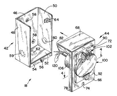
As shown in Fig. 2, power inlet box 18 generally includes a housing or base
member 42 and a cover assembly 44. Base member 42 includes a rear wall 46 and a pair of
side walls 48, 50 extending forwardly from the sides of rear wall 46. A bottom wall 52
20 extends forwardly from the lower end of rear wall 46, and extends between the lower ends
of side walls 48, 50. Bottom wall 52 defines a flange 54 at its outer end. An opening is
formed in the center of flange 54, and a threaded fastener 56, such as a screw, is threadedly
engageable with the opening in flange 54.
A series of openings 58 are formed in rear wall 46, for use in mounting base
25 member 42 to wall 22. Side walls 48, 50 include knock out sections 59, 60, respectively,
and bottom wall 52 includes a knock out section 62. Similarly, rear wall 46 includes a
knock out section (not shown) like knock out sections 59, 60 and 62, in a manner as is
known. A ground t~rrnin~l 64 is mounted to sidewall 50.
Referring to Figs. 2 and 3, cover assembly 44 includes a front wall 66 and a
30 top wall 68 extending rearwardly from the upper end of front wall 66. Front wall 66
includes a central opening 70. A power receptacle socket assembly, shown generally at 72,
is mounted to front wall 66 and extends through opening 70. A slot 74 extends vertically
upwardly from the lower edge of front wall 66. In addition, a series of holes 76 are formed
in front wall 66, spaced outwardly from the edge of opening 70.
CA 022~443 1998-12-07
A pair of side flanges 78, 80 extend rearwardly from the side edges of front
wall 66, throughout the height of front wall 66. Similarly, a pair of flanges, one of which is
shown at 82, extend downwardly from the side edges of top wall 68 throughout the length of
top wall 68. A flange similar to flange 82 extends downwardly from the rear edge of top
5 wall 68 between the side flanges.
Referring to Figs. 3 and 4, socket assembly 72 includes a socket base 86 and a
socket member 88. Socket base 86 includes plate-like upper and lower portions 90, 92,
respectively, extenllinp in opposite directions from a central ring defined by a peripheral
upst~n~ling wall 94. An annular flange or shoulder 96 extends inwardly from the inner
10 surface of wall 94, defining a central opening 98.
An access cover 100 is interconnected with socket base 86 via a conventional
hinge mounting arrangement, shown at 102. A sealing gasket 104is mounted to the inside
surface of access cover 100. In a manner as is known, cover 100 is pivotable via hinge
arrangement 102 between an open position as shown, and a closed position in which cover
100 engages the outer edge of wall 94, such that access cover 100 overlies the area enclosed
by wall 94. Hinge arrangement 102 includes a conventional pivot pin defining the pivot axis
of cover 100, and a torsion spring for biasing cover 100 toward its closed position.
Socket member 88 includes a cylindrical side wall 106 termin~ting in an inner
end wall 108 having a central opening 110. A flange 112 extends outwardly from the outer
end of side wall 106.
A receptacle block 114 having a series of outwardly extending prongs 116 is
mounted in the interior of socket member 88 via a pair of fasteners such as 118 which
engage threaded openings formed in inner end wall 108. Receptacle block 114 includes
terminals adapted to receive and electrically engage a series of wires, shown at 120, for
conducting power to prongs 116 and for providing a ground connection for receptacle block
114, in a manner as is known.
In assembly, socket member 88 is mounted to socket base 86 by inserting
socket member 88 through socket base opening 98. A gasket ring 122 is slipped over socket
member side wall 106 into engagement with the rear side of flange 112, such that gasket
ring 122 is disposed between flange 112 and annular shoulder 96. Screws such as 124
extend through openings formed in flange 112 and into aligned, threaded openings formed in
shoulder 96, to securely mount socket member 88 to socket base 86. Gasket 122 issandwiched between flange 112 and shoulder 96, to provide a water-tight seal therebetween.
CA 022~443 1998-12-07
When initially installing power inlet box 18 on wall 22, the installer secures
power inlet box base member 42 to wall 22 and then engages a conduit fitting, such as 26,
with base member 42 using one of knock-out sections 59, 60 or 62, as appropriate. Other
conduits and fittings are installed as desired, and the installer then threads wiring such as 120
through the conduit fitting 26 and into the internal cavity of base member 42. Alternatively,
wiring 120 can extend into the internal cavity of base member 42 through the knock out
section in base member rear wall 46. The installer then draws the ends of wires 120 out of
the internal cavity defined by base member 42, and threads the wires 120 through opening
110 in socket member 88 for connection to receptacle block 114. Receptacle block 114 is
10 typically pre-mounted by the manufacturer in the interior of socket member 88 using screws
124, to complete assembly of socket assembly 72.
To facilitate on-site installation, socket assembly 72 is preferably fully
assembled and mounted to cover member front wall 66 by the manufacturer, such that field
installation simply entails connection of wires 120 to receptacle block 114. Socket assembly
15 72 is mounted to cover member front wall 66 by inserting socket member 88, which extends
rearwardly from socket base 86, through opening 70 formed in cover member front wall 66
such that socket base 86 engages front wall 66. A gasket 126 is placed between socket base
86 and cover member front wall 66, to provide a water-tight seal preventing ingress of water
through opening 70. Screws such as 128 engage holes 76 in front wall 66 and extend
20 through aligned openings in upper and lower portions 90, 92 of socket base 86, and are
tightened to securely mount socket base 86, and thereby socket assembly 72, to cover
member front wall 66.
When socket assembly 72 is assembled in this manner and mounted to front
wall 66 as shown in Fig. 2, with wires 120 mounted to receptacle block 114, cover member
25 44 is then engaged with base member 42 to complete assembly of inlet box 18. To engage
cover member 44 with base member 42, the user first positions cover member 44 such that
upper wall 68 is located above the upper ends of wàlls 46-50 and rear wall 46 is located
outwardly of the outer ends of side walls 48, 50 and bottom wall 52. The user then moves
cover member 44 laterally inwardly toward base member 42, such that cover member top
30 wall 48 is located over the upwardly facing opening defined by the upper edges of side walls
48, 50 and rear wall 46. In this position, the rear flange which extends downwardly from
the rear edge of top wall 68 is located rearwardly of base member rear wall 46. Prior to
positioning of cover member 44 in this manner, the user has access to the internal cavity
defined by base member 42 either through the upwardly facing opening defined by the upper
CA 022~443 1998-12-07
edges of walls 46-50 or through the forwardly facing opening defined by the outer edges of
walls 48, 50 and 52. When cover member 44 is positioned in this manner such that top wall
68 overlies the upwardly facing opening defined by base member 42, the user still has access
to the internal cavity defined by base member 42 through the forwardly facing opening
5 above bottom wall 52 and below the lower end of cover member front wall 66. This enables
the user to relatively easily manipulate and position wires 120 within the internal cavity
defined by base member 42. The user then moves cover member 44 downwardly relative to
base member 42, such that the underside of top wall 68 engages the upper ends of the side
walls 48, 50 and rear wall 46 to enclose the top opening of base member 42. In this
10 position, the rear flange which extends downwardly from the rear edge of top wall 68 is
located rearwardly of the upper end of rear wall 46, and likewise the side flanges, such as
82, which extend downwardly from the side edges of top wall 68 extend downwardly past
the upper edges of base member side walls 48, 50. The depending top wall flanges thus
overlap walls 46-50, to provide a shingle structure preventing ingress of water into the
internal cavity of base member 42. Similarly, side flanges 78, 80 overlap the front edges of
side walls 48, 50, to again prevent ingress of water into the internal cavity of base member
42 through the front opening of base member 42.
When cover member 44 is installed on base member 42 in this manner, slot
74 in the lower edge of cover member front wall 66 receives the shank of screw 56 mounted
to base member bottom wall 52. To secure cover member 44 in position, the user tightens
screw 56 such that its head engages cover member front wall 66 adjacent slot 74. In
combination with the rear flange depending downwardly from the rearward edge of cover
member top wall 68, this functions to securely mount cover member 44 to base member 42.
As can be appreciated, the provision of openings in base member 42 which
face both outwardly and upwardly provides the dual function of facilitating handling of
wires, such as 120, when mounting cover member 44 to base member 42, as well as
providing a weather resistant structure for preventing water from entering the internal cavity
by enclosing the base member upwardly facing opening with a top ~vall associated with the
cover member.
Fig. 5 illustrates an alternative cover member, shown at 44', for use in place
of cover member 44, and like reference characters will be used where possible to facilitate
clarity. Cover member 44' includes a front wall 66 and a top wall 68 like cover member 44,
with the only exception being the provision of holes 132 adjacent opening 70 in cover
member 44' in place of holes 76 of cover member 44. In all other respects, front wall 66
CA 022~443 1998-12-07
and top wall 68 are the same for cover member 44' as for cover member 44, including the
depending flanges such as 78, 80 and 82.
Cover member 44' includes a socket assembly 134 which has several
components in common with socket assembly 72 of Figs. 1-4, and again like reference
characters will be used to facilitate clarity. Socket assembly 134 includes socket member 88,
gasket ring 122 and receptacle block 114. In this embodiment, a mounting adaptor 136 is
interposed between socket member 88 and front wall 66.
Mounting adaptor 136 includes a ring-shaped wall 138 having an annular
shoulder 140 exten~ling inwardly therefrom and t~rmin~ting in an inwardly facing edge
10 defining an opening 142. Spaced apertures 144 are formed in shoulder 140. Hinge arrange-
ment 102 is mounted to wall 138, for pivotably mounting access cover 100 to wall 138.
Gasket 104 is adapted for mounting to the inside of access cover 100.
To facilitate on-site installation, socket assembly 134 is again preferably fully
assembly by the manufacturer and mounted to front wall 66. Receptacle block 114 is
15 secured within the interior of socket member 88 using fasteners 118. Socket member 88 is
engaged with front wall 66 such that the body of socket member 88 extends through gasket
122, mounting adaptor opening 142 and front wall opening 70. Gasket 122 is engaged with
the rear surface of socket member flange 112, and is sandwiched between flange 112 and
mounting adaptor shoulder 140. An additional gasket (not shown) may be placed between
20 front wall 66 and the rearwardly facing surface of wall 138. Mounting adaptor 136 is
engaged with the outer surface of front wall 66 over opening 70, and openings 144 in
mounting adaptor shoulder 140 are aligned with holes 132 in cover member front wall 66.
Fasteners 124 extend through aligned openings formed in socket member flange 112 and
gasket 122, through apertures 144 in shoulder 140 and into threaded engagement with holes
25 132. In this manner, mounting adaptor 132 and socket member 88 are secured to front wall
66 as a unit. This elimin~tes the need for fasteners 128 in the embodiment of Figs. 1-4,
which function to secure socket base member 86 to front wall 66 separately from securement
of socket member 88. The embodiment of Figs. 5-7 provides a quick and easy method for
mounting socket assembly 134 to cover member front wall 66.
At the time of in~t~ tion, the user simply connects wire 120 to receptacle
block 114 through mounting adaptor opening 142. Cover member 44' is then engaged with
base member 42 in the same manner as described previously with respect to cover member
44.
.. ~, .. . .. ..
CA 022~443 1998-12-07
- 10 -
Figs. 8 and 9 illustrate an alternative socket assembly, shown at 150, for use
in combination with cover member 44'. Socket assembly 150 essentially consists of socket
member 88 and mounting adaptor 136 of Fig. 7, formed integrally with each other. With
this construction, socket member flange 112 and mounting adaptor shoulder 140 are
5 combined into a single flange 152 having spaced apertures adapted for alignment with
apertures 132 in front wall 66 of cover member 44'. An outwardly extending peripheral
wall 154 extends from the outer edge of flange 152, and hinge arrangement 102 is intercon-
nected with wall 154 and flange 152 for pivotably mounting access cover 100. Again,
gasket 104 is adapted for engagement with the inside surface of access cover 100, which is
10 pivotable about hinge arrangement 102 between an open position as shown in Fig. 8 and a
closed position as shown in Fig. 9. A cylindrical socket member 156 extends rearwardly
from the inner edge of flange 152, and has generally the same construction as socket
member 88 of Figs. 1-7. Receptacle block 114 is mounted to socket member 156 as shown
and described above, including the connection of wires 120 to receptacle block 114.
In the embodiment of Fig. 9, gasket 122 is placed between the rearwardly
facing surface of flange 152 and the forwardly facing surface of cover member front wall
66. Screws 124 extend through the spaced openings in flange 152 through aligned spaced
openings in gasket 122, and into threaded engagement with openings 132 in cover member
front wall 66 for securing socket assembly 150 to cover member 44'. As can be readily
20 appreciated, this construction reduces the overall number of parts required for the socket
assembly and simplifies mounting of the socket assembly to the cover member by reducing
the overall number of parts required for manufacture and installation.
Various alternatives and embodiments are contemplated as being within the
scope of the following claims particularly pointing out and distinctly claiming the subject
25 matter regarded as the invention.
.. . ... ... .. .. ..