Note: Descriptions are shown in the official language in which they were submitted.
CA 022~679 1998-11-16
WO 97/43914 PCT/EP97/02711 '
METHOD FOR PRESERVATION UNDER PRESSURE
The present invention is concerned with a method for
preservation, particularly ultra high pressure
preservation. The method i9 used for operation in a
5 continuous mode and is particularly suitable in the food
industry.
STATE OF T~E ART
Industrially prepared food usually has to be subjected to a
preservation treatment in order to prevent spoilage during
subse~uent storage. Ultra-high pressure (UHP) preservation
is a preservation method which only relatively recently has
15 been developed for industrial application, although the
lethal effect of ultra-high pressure on micro-org~n; ~m~ has
been discovered already in the previous century by B.H.
Hite. A review of the state of the art can be found in New
Methods of Food Preservation (1995, ed. G.W. Gould). UHP
20 preservation is the cubject of many patents: e.g. US
4,873,094, US 5,228,394, US 4,873,094 and US 5,228,394.
NL 102 914 describes conducting a spread-like product
through a narrow tube under an initial pressure of 40
... . .. .. . ... ....... . .
CA 022~679 1998-11-16
WO97/43914 PCT~P97/02711
atmospheres with a beneficial effect on the consistency of
the product. This pressure however, is not high enough to
have a signi~icant effect on the viability of micro-
organisms in the product.
Substances treated in a homogenizer are exposed also to a
very high pressure, but during a very short time (several
milliseconds). In such a device the shear forces exerted on
the substance during the pressure drop are enormous and
l0 often damage the product structure. Moreover the energy
needed for passing the product through the homogenizing
clearance dissipates quickly in a small volume of the
shearing device resulting in a local, unacceptably high
temperature rise. Usually this rise is approximately 5~C
15 per 20 MPa of pressure drop, the rise also depending on the
thermal capacity and heat conductivity of the product.
A major disadvantage of known UHP preservation techniques
is that UHP preservation is applied only batch-wise. Since
20 most food processing is operated in a continuous mode, an
UHP preservation method which could be operated as a
continuous process would fulfill a need. Only WO 95/22912
describes UHP equipment with which a semi-continuous
process can be carried out. Present equipment for UHP
25 processing is complicated and so expensive that it impedes
an economic use and consequently the general employment of
UHP preservation.
STATEMENT OF lNv~lON
We have found an unexpectedly feasible combination of two
seemingly controversial conditions: the one condition being
maintenance of a high k;nPm~tic pressure in a tube which is
35 relatively narrow and open at the exit end, which kinematic
pressure in at least a part of the tube is sufficiently
high that a microbiologically cont~m;n~ted fluid during i~
flowing through the tube gets decontAm;n~ted, the other
CA 022~679 1998-11-16
WO97/43914 PCT~P97102711
condition being the realisation of a flow which is high
enough to make the process economically feasible.
The invention therefore provides a method for decreasing
5 the viability of micro-organisms and/or the activity of
enzymes in a contaminated substance by exerting a high
pressure to the substance, characterized in that the
substance is conducted in a steady flow through a tube,
while the pressure difference between the entrance end and
l0 the exit end of the tube is maintained at l00 MPa or more.
The present method allows a fully continuous UHP
preservation process.
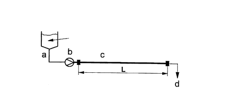
DESCRIPTION OF TEE FIG~RE
Figure l shows a schematic view of the equipment with which
the invention can be carried out. c is a tube with a length
L and an inner diameter d. a is a storage container
20 connected to the entrance of the tube via a pressure unit
b. At d the open orifice of the tube is situated.
DETAILS OF THE lNVkNLlON
The invention essentially is carried out by feeding the
substance from the storage container a to the entrance of
the tube via a pressure unit b and passing it through the
tube to the exit at the right hand side.
The invention can be applied on all types of fluid
substances which need a decontAm;nAtion treatment, provided
they have a consistency which allows a sufficiently quick
passage through the necessarily small tubes employed with
35 the invention. Such substances comprise pharmaceutical
substances, clinical liquids, and particularly food
products such as spreads, mayonnaise, dressings, milk, tea
and even heat sensitive products as ice-cream and soft
,, , ~ . . .. . ... . .
CA 022~679 1998-11-16
WO97/43914 PCT~P97/02711
cheese. The invention is particularly suitable for
substances which tolerate only gentle treatments.
The substance may be a final food product or an ingredient
(or a mixture of ingredients) used for the preparation of a
5 food product, including even such nature originating
substances as herbs, provided they can be incorporated in a
fluid carrier substance which can be pumped through the
narrow tube.
lO In order to maintain a pressure of at least lO0 MPa between
the entrance and the exit of the tube, a proper balance
should be found between on the one side the diameter and
length of the tube and on the other side the given
viscosity and the desired flow of the product to be
15 treated. The mln;ml~m volume V of the tube results from the
formula
V = t * f,
where t is the m;nlml~m residence time for effective
20 decont~m;n~tion and f is the desired flow.
The residence time can be adjusted without changing the
narrow tube ~;men~ions by inserting a chamber at the
upstream end of the narrow tube, between the exit of the
pressure device and the entrance of the narrow tube. With
25 such chamber the ultra high pressure volume is increased
and consequently the residence time of the fluid. Because
of its resistance against high pressures, such chamber
preferably is a tube too, which diameter is greater than
the narrow tube diamter so that pressure drop and flow are
30 not substantially influenced by the presence of the
chamber. Preferably such chamber has a diameter which is at
least 5 times greater than the narrow tube diameter. The
following description of a tube is not applicable to this
residence chamber, but rather to the attached narrow tube.
35 Unless it is indicated otherwise, the term tube is used for
the narrow tube.
CA 022~679 1998-11-16
WO97/43914 PCT~P97/02711
In the context of the present description a tube is
considered to be a round vessel with two openings at both
ends of the vessel where the length of the vessel is at
least ten times the width of the vessel. Generally, the
5 ratio of the length and the average diameter of a tube
suitable for the invention is at least lO00, preferably at
least lO,000. Generally this means a diameter of only
several millimeters and a length of at least several
meters. The optimum ~;m~n~ions can be easily found by some
lO calculation and experimentation. Good results can be
obtained with a tube having a length of only 200 m and an
internal diameter of lO mm. It is much surprising that food
products which often have a rather viscous consistency can
be pressed through such tube at a flow rate sufficient for
15 economic processing. With said open tubes an output per
hour of about S0 liter product having an oily viscosity can
be realized by exerting a pressure of lO00 MPa. The high
flows needed in practice are realized by combining into
bundles large numbers of parallel tubes. See also Table I
20 for examples of suitable tube ~;men~ions in relation to
given substance viscosity and exerted pressure.
Pressure building in an open tube was believed to be
possible only with extremely long tubes. However, an
25 unexpectedly favourable pressure dependent viscosity
behaviour is observed.
The pressure within the tube should be at least lO0 MPa,
but pressures of at least 300 MPa are preferred. Generally
30 higher pressures allow shorter decontAm;nAtion times.
The ultra high pressures needed for working the invention
can be withstood best by tubes with relatively narrow
diameters: lO mm or less is preferred. Special
35 reinforcement is not necessary. The present preservation
device does not need the very thick walls of prior art
equipment.
CA 0225s67s 1998-11-16
W O 97143914 PCTrEP97/02711 -
Tl~B~E I
Fluid P L d L/d Visc. Flow
MPa m m Pa.s l/h
1 751 1000.0010100000 0.001 50
2 566 lQ0o.0010100000 0.01 50
3 559 1000.0015 66667 0.05 50
4 S39 1000.0018 55556 0.1 50
377 1000.0035 28571 1 50
6 437 1000.0060 16667 10 50
7 566 1000.0100 10000 100 50
~ 546 1000.0012 83333 0.1 10
9 707 1000.0020 50000 0.1 100
442 1000.0040 25000 0.1 1000
11 699 10000.0030333333 0.1 50
15 12 566 10 0.0010 10000 0.1 50
13 354 10 0.0020 5000 1 sO
Applicable to fluids having a density of about 1000 ~g/m3
20 and a heat capacity of 4.2 J/g.K
P : pressure drop in Megapascal
d : average diameter of tube in meters
Flow : flow rate in liters per hour
L : length of tube in meters
25 Visc : viscosity in Pascal seconds
The tube may be placed in any position, but preferably a
compact form such as a coil is chosen. Tubes having a
circular inter~ection are most advantageous in resisting
CA 022~679 1998-11-16
WO 97/43914 PCT/EP97102711 ~
high pressures, but other forms of intersections are not
excluded.
Glass and stainless steel, substances which are compatible
with food, are preferred tube materials.
For the pressure device or unit a choice can be made from
the devices found on the market which are meant for pumping
fluids under ultra high pressures.
10 In order that the exerted pressure has a sufficient effect
on the micro-organisms, the residence time of the fluid in
the tube should be at least 1 second. Generally, longer
residence times are needed when the pressure is lower than
350 MPa. Preferably the residence time is at least 2
15 minutes, more preferably at least 5 minutes and still more
preferably at least 10 minutes.
It is difficult to give general rules since the flow
behaviour of the substance processed under UHP conditions
20 generally can not be predicted. Given a particular
substance, some experimentation will easily provide the
proper combination of tube ~jmPn~ions and pressure.
The present device operates with a permanently open orifice
25 at the end of the tube. The effect is a pressure gradient
along the whole length of the tube. Consequently the
pressure in the tube is higher in upstream parts than in
downstream parts of the tube, with the effect that
decontAm;n~tion takes place pre~om;n~ntly in the upstream
30 part of the tube.
High pressure energy is dissipated evenly over the whole
length of the tube.
Within the tube the shear forces are relatively small.
35 Moreover both the relatively large external surface of the
tube in relation to the volume of the tube and the
relatively thin wall of the tube allow an easy control of
the temperature of the tube's content if necessary with the
,~ .... ,, , . ,.. . . .. ., . ~..................... . ....... . .
CA 022~5679 1998-11-16
W O 97/43914 PCT/EP97/02711-
help of additional cooling. The temperature rise of the
processed substance during tube passage can be confined to
less than 10~C, preferably less than 5~C. This fits into
modern concepts to avoid as much as possible unnecessary
5 heating of industrially prepared food.
Operating the process at a temperature different from
ambient temperature may be advantageous. When the
temperature is lowered, the viscosity will increase which
10 makes it possible to maintain the pressure at the desired
level even when the fluid to be treated is not sufficiently
viscous at ambient temperature.
A temperature increase will cause a lowered viscosity and
an advantageous increase of the flow will result. Such
15 increase will meet the obvious limitation that the
substance to be treated needs a min~ml~m residence time in
the tube.
The present invention gives a method which allows the
20 decontamination of food products where the use of
preserving ingredients, a low pH or the use of heating is
undesirable.
Nevertheless the present UHP method may be used in
combination with one or more other preservation methods.
25 When combining methods, often much less severe over-all
conditions will suffice for att~;n;ng the required
decont~m;n~tion degree.
A particularly effective combination is the application of
lethal pulsating electrical or magnetic fields to the
30 substance when it passes through the high pressure tube.
The process of the invention inactivates vegetative cells.
For the inactivation of microbial spores generally a higher
pressure and/or a longer exposure time should be applied.
35 Affected micro-organisms include bacteria as well a~ moulds
and yeasts, but also viruses. Although full sterilization
of the product in principle is possible, often a lesser
CA 022~679 1998-11-16
WO97/43914 PCT~P97102711
degree of decontamination suffices, so that less severe
process conditions can be applied.
UHP preservation has the additional advantage that also
enzymes are fully or partially deactivated.
In the context of this specification with a substantial
decrease in viability is meant a reduction in the viable
microorganisms count with a factor lO00 or higher. This is
often expressed as logcycle reduction (log (N0/Nt)) which
lO should be 3 or higher. Nt is the count after the process
and N0 before the process.
The present method distinguishes itself from prior art
methods by its surprising simplicity which not only
15 contributes to economy but also to process reliability.
The invention is further illustrated by the following
example:
Example 1
In lO00 ml of glycerol lO00 cells per ml of the yeast
Saccharomyces cerevisiae have been dispersed. The
25 dispersion in which a natural contAm;nAtion condition was
emulated was conducted through a tube with a length of 25 m
and a diameter of l mm with a pressure of 300 MPa at the
entrance of the tube. The residence time in the tube was 60
seconds and the temperature was ambient temperature, 2l~C.
30 The substance collected at the end of the tube was assayed
on contAm;nAtion, but no detectable amount of yeast cells
could be established.
, . . . . . . . . . .