Note: Descriptions are shown in the official language in which they were submitted.
CA 02255777 1998-11-23
F i LF.
õ-."''~'
SPECIFICATION
COATING APPARATUS, PRINTING APPARATUS, IMAGING APPARATUS,
PRINTING SYSTEM AND PRINTING METHOD
TECHNICAL FIELD
The present invention relates to a coating apparatus, a
printing apparatus, an imaging apparatus, an imaging method,
an imaging medium, a printing system, and a printing method.
BACKGROUND ART
As a technique of this type of printing apparatus, there
are known the techniques disclosed in, for example, Unexamined
Japanese Patent Publication No. 54-152504 (corresponding to
U.S.P No. 4,280,406), Examined Japanese Patent Publication No.
55-28860 (corresponding to U.S.P. No. 4,141,293), and Examined
Japanese Patent Publication No. 3-71983.
In the printing apparatus of Unexamined Japanese Patent
Publication No. 54-152504, as shown in FIG. 29, plate cylinders
1041 to 1044 and blanket cylinders 1051 to 1054, which were
positioned at an ink coating apparatus setting side separately
from a feeding side for web paper and a discharging side for
paper cut into sheets, were arranged in the same frame to be
slidably drawn. This resulted in easy plate replacements, and
easy change of a print format, and operability of the printing
apparatus was improved.
In Examined Japanese Patent Publication No. 55-28860, as
shown in FIG. 30, in order to carry out multicolor printing on
continuous paper, a plurality of print units was vertically
arranged, thereby reducing a setting floor area for the printing
apparatus. Also, the ink coating apparatus were provided on
the same side, so that easy plate replacements were achieved.
In the printing apparatus of Examined Japanese Patent
Publication No. 3-71983, as shown in FIG. 31, spaces for setting
CA 02255777 1998-11-23
2
dampening water apparatuses are omitted by use of waterless
plates. Instead, a plate feed and discharge device was provided
to the omitted space for each plate cylinder so as to improve
operability.
As a technique of the coating apparatus used in these
printing apparatus, there are known the techniques disclosed
in, for example, Unexamined Japanese Patent Publication No.
57-178872, Unexamined Japanese Utility Model Publication No.
56-76438, and Examined Japanese Patent Publication No. 4-68147.
These techniques are used as an ink coating technique for the
printing apparatus, and frequently employed mainly in waterless
lithographic printing, a letterpress printing, etc. In
particular, Examined Japanese Patent Publication No. 4-68147
disclosed a coating apparatus having a coating roller with an
elastic surface, and a doctor blade, which freely moved back
and forth to the outer peripheral surface of the coating roller
and controlled a thickness of a coated ink film to be formed
on the outer peripheral surface. This was an extremely useful
coating technique when ink having high viscosity was used.
The feature of the techniques used in these coating
apparatus is that the doctor blade is used as a method for setting
the thickness of the ink film to be applied onto the coating
roller. For example, in the technique of Examined Japanese
Patent Publication No. 4-68147, as shown in FIG. 32, an ink unit
1002, serving as an ink coating apparatus, comprises an form
roller 1201, a doctor blade 1202, an eccentric cam 1203 for
controlling the movement of the doctor blade, ink distributing
rollers 1210, 1211, and an auxiliary form roller 1212 having
an elastic surface. The form roller 1201, the doctor blade 1202,
side plates 1207 and 1208, which are arranged at both sides of
the form roller 1201 in its axial direction, and an ink fountain
1206 form an ink fountain space 1205, which is filled with
printing ink i.
CA 02255777 1998-11-23
3
A small gear (not shown) rotating solidly with the form
roller 1201 is engaged with a large gear (not shown) rotating
solidly with a plate cylinder 1015. Thus, the form roller 1201
and the plate cylinder 1015 are synchronized with each other
and rotated at the same circumferential speed at their contact
section.
The ink unit 1002 is configured so that the eccentric cam
1203 attached to a shaft 1204 is rotated so as to move the doctor
blade 1202 back and fourth in a direction of an arrow A, thereby
changes the engagement between the doctor blade 1202 and the
form roller 1201 in order to control the thickness of the coated
ink film formed on the outer periphery of the form roller 1201.
Conventionally, a printing plate, serving as an imaging
medium used in such a printing apparatus, has been generally
manufactured by a photomechanical process in which a lith type
film (lithographic film) for plate-making is applied to a PS
plate (presensitized plate or the like). Since the plate-
making apparatus and the printing apparatus are normally
independent devices, the positioning of the imaging medium of
each color in the multicolor printing is carried out by the
following process.
At the outset register marks was drawn on the imaging
medium for each color. Then, the imaging medium for each color
was installed around each plate cylinder of the printing
apparatus. Ink was fed to the imaging medium of each color,
and printing was performed on a recording medium such as paper.
Then, the positions of the imaging mediums of the respective
colors in the printing apparatus and the print timing were
adjusted until the positions of the register marks printed on
the recording mediums of the respective colors were coincide
with each other. Thus the mutual positions of the imaging
mediums of the respective colors were determined.
In recent years, there has been increased the use of the
CA 02255777 1998-11-23
4
imaging apparatus for making the printing plate, which serves
as the imaging medium, based on digital imaging information in
accordance with imaging data. As an imaging medium fixing
method in these imaging apparatuses, there are known techniques
disclosed in Unexamined Japanese Patent Publication No. 3-24549
(corresponding to U.S.P.No.5,094,933)and Unexamined Japanese
Patent Publication No. 5-8366.
In the apparatus of Unexamined Japanese Patent
Publication No. 3-24549, as shown in FIG. 33, after imaging on
a web imaging medium, the imaging medium is cut to a
predetermined size, developed and carried by a transfer roller
or a conveyor belt.
In Unexamined Japanese Patent Publication No. 5-8366, as
shown in FIG. 34, the imaging medium is wound around an attaching
member and rotated, and imaging is executed by irradiation of
an energy beam. The imaging medium is fixed to the plate
cylinders with flat-headed screws, or adhered thereto with
adhesive.
As a technique in which the imaging medium is wound around
an attaching member and rotated, and imaging is executed by
irradiation of the energy beam, the imaging apparatus disclosed
in Unexamined Japanese Patent Publication No. 5-8366 was
configured as described as follows.
That is, the attaching member to which the imaging medium
was attached was rotated and the energy beam scans in a
circumferential direction of the imaging medium. Also, the
laser block having a semiconductor laser is scanned in the axial
direction of the attaching member by use of a ball screw.
The shaft of the attaching member and the ball screw are
arranged to be parallel with the axial direction of the
attaching member. The scanning in the axial direction is
executed for each scanning in the circumferential direction
while the attaching member is rotated. The scanning is
CA 02255777 1998-11-23
performed over the entire surface of the imaging medium thereby
imaging is executed.
The imaging apparatus disclosed in Unexamined Japanese
Patent Publication No. 8-72311 is configured as follows.
5 That is, as shown in FIG. 35, the imaging medium, which
is wound around the attaching member and rotates, is irradiated
with the energy beam from a plurality of recording heads having
a plurality of energy beam irradiation sources, so as to execute
imaging. The imaging medium, which is wound around the
attaching member and rotates, is scanned in the circumferential
direction by its rotation and simultaneously, the recording
heads are scanned in the axial direction of the attaching member
by a linear motor, etc. Therefore, the rotation shaft of the
attaching member and a carriage apparatus such as a linear motor,
which scans the plurality of recording heads in the axial
direction of the attaching member, are arranged in parallel with
respect to the axial direction of the attaching member.
The energy beam irradiation position is determined by
detecting means for detecting the position of a beam spot light
of the energy beam and means for correcting the irradiation
position of the beam spot light to the attaching member based
on the output from the detecting means.
However, in the printing apparatus of Unexamined
Japanese Patent Publication No. 54-152504 shown in FIG. 29,
there was a problem in that it was impossible to carry out a
back face printing after feeding a sheet of paper. When the
interval between grippers for gripping paper on an impression
cylinder 1031 in the circumferential direction is shorter than
a length of the sheet of paper to be printed in the progress
direction the paper is sandwiched between the pressure cylinder
1031 and blanket cylinders at two portions simultaneously so
that the paper is suffered some tension. As a result, if the
printing position may shift, which is a problem. Moreover, the
CA 02255777 1998-11-23
6
interval between the grippers for gripping paper is increased
in order to solve the problem, the ink coating apparatuses could
not be arranged for three or more color printing, which is also
a problem.
On the other hand, if the impression cylinder 1031 is
enlarged in order to arrange the ink coating apparatus, the
diameter of the impression cylinder 1031 becomes too large, and
the entire printing apparatus must be enlarged. As a result,
a large setting space for such a printing apparatus was required
and the cost of the impression cylinder 1031 was increased, so
that the printing apparatus became expensive.
The method disclosed in Examined Japanese Patent
Publication No. 55-28860 was limited to the printing apparatus
using continuous webs, and could not be applied to the printing
apparatus using sheets of paper. In the technique disclosed
in Examined Japanese Patent Publication No. 3-71983, since one
blanket cylinder was shared by two ink coating apparatus, there
occurred a problem in which process color printing could not
be carried out. Also, since one blanket cylinder was shared
by two ink coating apparatus, the distance of the ink coating
apparatus could not be increased due to the structure of the
printing apparatus, so that workability of plate replacements
became worse. In the technique disclosed in Examined Japanese
Patent Publication No. 3-71983, a plate feeding and discharging
apparatus was used to improve workability. Though the plate
was easily replaced by use of the plate feeding and discharging
apparatus, there occurred a problem in which the printing
apparatus became expensive.
In the ink coating apparatus disclosed in Examined
Japanese Patent Publication No. 4-68147, there was a problem
in which striped defects were generated in the circumferential
direction of the surface of the coated ink film because of paper
dust clogged at the doctor blade portion as shown in FIG. 6.
CA 02255777 1998-11-23
7
In other words, when the doctor blade portion is clogged with
paper dust, a form roller 1201 bends at the clogging portion
and escapes therefrom. Since the thickness of the ink layer
of this portion is increased and the portion between the doctor
blade 1202 and the form roller 1201 is clogged with paper dust,
striped defects 1252 are generated in an ink layer in the
circumferential direction.
Since the defects were left in the ink layer on the coating
roller as a deep groove, such troublesome defects could not be
easily eliminated even if the distributing roller is simply
used.
In the imaging apparatus disclosed in Unexamined Japanese
Patent Publication No. 3-24549, the printing plate, which is
the imaging medium exposed and developed, is cut by a built-in
cutting apparatus, thereafter the printing plate is
automatically on the imaging apparatus. According to such the
imaging apparatus, the positioning of the mutual printing
positions of imaging mediums of the respective colors was not
accurately made in the multicolor printing apparatus. As a
result, there was a problem in which the mutual printing
positions of imaging mediums of the respective colors had to
be adjusted again before continuous printing was executed.
Unexamined Japanese Patent Publication No. 5-8366
describes a method in which the imaging medium is fixed to the
plate cylinder with a flat-headed screw, or adhered thereto with
adhesive. However, the positioning of the imaging medium and
that of the print pattern cannot be accurately made. Moreover,
this publication describes no specific method other than the
positioning of the imaging medium and that of the print pattern.
Therefore, in the imaging medium prepared by the apparatus as
described in Unexamined Japanese Patent Publication No. 5-8366,
there was no other way than the aforementioned method of
positioning the register marks in connection with the
CA 02255777 1998-11-23
8
positioning method at attaching of the imaging medium to the
printing apparatus.
On the other hand, the printing apparatus having a laser
head for imaging is known. In this apparatus, imaging is
executed after imaging medium is wound around the plate cylinder,
and ink is directly fed and printing is executed. In this
apparatus, if the positional relationship between the plate
cylinder and the imaging head are made to completely
corresponding to each other for each color, the positioning of
the imaging medium can be omitted or largely simplified at the
printing time.
However, the above printing apparatus can neither perform
imaging during the printing and nor print during the imaging
when the imaging head is provided therein. It cannot avoid a
decrease in productivity as a printing apparatus or independent
apparatus. In addition, since the imaging head occupies most
of the manufacturing cost of the imaging apparatus. If the head
is provided for each plate cylinder of each color, the
manufacturing cost of the entire apparatus is largely increased.
One imaging apparatus is not necessary for one printing
apparatus. Generally, imaging mediums to be used for many
printing apparatus are made by one imaging apparatus. As
compared with the case in which the printing apparatus and the
imaging apparatus are separately provided as a different
structure, the structure in which the imaging apparatus is
provided in the printing apparatus as in the above-mentioned
apparatus has demerits in terms of productivity and the
manufacturing cost.
As explained above, the mutual positioning of the image
patterns for the respective colors in the multicolor printing
was performed as the follows . That is, the positioning was made
by adjusting the position of the plates in the printing
apparatus and the timing such that the positions of the register
CA 02255777 1998-11-23
9
marks printed on the recording mediums for the respective colors
were coincide with each other.
Hence, simple installing of the imaging medium S which
were directly prepared by the imaging apparatus to the printing
apparatus cannot achieve accurate positioning of the imaging
mediums.
Moreover, there has been no imaging apparatus in which
some contrivance was added to a positioning hole size, which
was necessary for adjusting the positions of the imaging mediums,
and chamfering of end portions of the imaging mediums for
another reason. Moreover, there was no imaging apparatus in
which the imaging medium attaching member was subjected to a
surface coating process to improve accuracy of attaching the
imaging medium to the imaging apparatus.
In the configuration that a beam irradiation apparatus
having a plurality of beam irradiation sources is continuously
scanned in the direction of a rotation axis of the attaching
member at a fixed speed as continuously rotating the attaching
member around which the imaging medium is wound at a fixed speed,
there was a problem in which the image was obliquely formed with
respect to a reference direction of an original imaging area
of the imaging medium.
In the imaging apparatus as shown in FIG. 34, the imaging
medium is rotated in a direction of an arrow R (rotational
direction of the attaching member) at peripheral speed Vr, and
that the beam irradiation apparatus is scanned in a direction
of an arrow S (direction of a rotation axis of the attaching
member) at feeding speed Vy. As shown in FIG. 27A, it would
be ideal if imaging dots 2092 formed in an imaging area 2091
of an imaging medium 2018 would be arranged in a matrix form
of rectangle along an arrow direction 93 of the imaging area
2091.
However, in the imaging apparatus as shown in FIG. 34,
CA 02255777 1998-11-23
since the beam irradiation apparatus is scanned in the direction
of the rotation axis of the attaching member as rotating the
attaching member, if the imaging medium 2018 is fixed to a plate
cylinder 2011, serving as the attaching member, such that the
5 reference direction of the imaging area is parallel to the
rotation axis of the plate cylinder 2011, and the scanning
direction of the beam irradiation apparatus completely coincide
with the direction of an arrow S(0= 0 in FIGS. 27A to 27C),
there occurred a problem in which the imaging dots 2092 were
10 deformed to be a parallelogram as shown in FIG. 27B.
A first object of the present invention is to provide a
multicolor printing apparatus in which the disadvantages of the
prior art can be improved in that a back face printing can be
easily carried out, and a good workability can be obtained.
A second object of the present invention is to provide
a multicolor printing apparatus in which a good printing quality
can be obtained, no large space is necessary for setting a
printing apparatus, and a manufacturing cost is reasonable.
A third object of the present invention is to provide an
duplex printing method for providing a good printing quality
at a small space easily.
A fourth object of the present invention is to provide
a coating apparatus in which disadvantages of the prior art can
be improved and striped defects are not easily generated in the
circumferential direction of the surface of the coated ink film
because of paper dust even when ink having high viscosity is
coated.
A fifth object of the present invention is to provide an
imaging apparatus in which the disadvantages of the prior art
can be improved in that the positioning of the printing position
at printing in that can be easily realized in a state that an
imaging apparatus and a printing apparatus are maintained as
independent structures, and provide a printing apparatus and
CA 02255777 2006-11-07
72465-75
11
a printing system, and an imaging method, and a printing
method.
A sixth object of the present invention is to
provide an imaging apparatus with a reasonable cost in which
disadvantages of the prior art can be improved in that an
image can be formed without having an inclination with
respect to the imaging medium, the positioning of the
imaging medium at an imaging time can be easily carried out
where an imaging apparatus and a printing apparatus are
independent structures, and an inclination of the image
position in the imaging medium can be restrained and
corrected, so that the positioning of printing plate in a
printing apparatus can be easily carried out, and provide an
imaging method and a printing system.
DISCLOSURE OF INVENTION
According to the present invention, there is
provided a multicolor printing apparatus including a
printing apparatus comprising: a plurality of blanket
cylinders normally-contacting to an impression cylinder;
plate cylinders normally-contacting to the respective
blanket cylinders; and ink coating apparatus for coating the
respective plate cylinders with ink, wherein said ink
coating apparatus are arranged in a line with respect to
each other in a substantially vertical direction parallel to
the direction in which gravity acts, a feeding apparatus for
feeding sheets of recording mediums to said printing
apparatus and a discharging apparatus for discharging sheets
of recording mediums are provided on a side opposite to a
setting side of said ink coating apparatus with respect to
said blanket cylinders, wherein said feeding apparatus for
feeding sheets of recording mediums is positioned at a lower
CA 02255777 2006-11-07
72465-75
12
side than the discharging apparatus such that said sheets of
recording mediums flow from a lower side to an upper side,
wherein the number of the impression cylinder is the plural
number, and wherein said impression cylinders are double-
diametered impression cylinders, and the transfer of the
recording mediums between said double-diametered impression
cylinders is carried out by a triple-diametered transfer
cylinder.
There is also provided a multicolor printing
apparatus including a printing apparatus comprising: a
plurality of blanket cylinders normally-contacting to an
impression cylinder; plate cylinders normally-contacting to
the respective blanket cylinders; and ink coating apparatus
for coating the respective plate cylinders with ink, wherein
said ink coating apparatus are arranged in a line with
respect to each other in a substantially vertical direction
parallel to the direction in which gravity acts, a feeding
apparatus for feeding sheets of recording mediums to said
printing apparatus and a discharging apparatus for
discharging sheets of recording mediums are provided on a
side opposite to a setting side of said ink coating
apparatus with respect to said blanket cylinders, wherein
said feeding apparatus for feeding sheets of recording
mediums is positioned at a lower side than the discharging
apparatus such that said sheets of recording mediums flow
from a lower side to an upper side, wherein the number of
the impression cylinder is the plural number, and wherein
said impression cylinders are triple-diametered impression
cylinders, and the transfer of the recording mediums between
said triple-diametered impression cylinders is carried out
by a double-diametered transfer cylinder.
CA 02255777 2006-11-07
72465-75
12a
According to a preferred embodiment of the present
invention, there is provided the multicolor printing
apparatus wherein each of the ink coating apparatus
comprises a coating roller with an elastic surface, and a
doctor blade, structured to move back and forth freely to
the outer peripheral surface of the coating roller, for
controlling the thickness of coated ink film formed on the
outer peripheral surface.
According to a preferred embodiment of the present
invention, there is provided the multicolor printing
apparatus further comprising means for drying coloring agent
on the sheets of recording mediums after discharging printed
sheets of recording mediums between the final blanket
cylinder and the final impression cylinder.
According to a preferred embodiment of the present
invention, there is provided the multicolor printing
apparatus further comprising a discharge station on which
the printed sheets of recording mediums are stacked after
the printed sheets
CA 02255777 1998-11-23
13
of recording mediums are discharged between the final blanket
cylinder and the final impression cylinder, the discharge
station is configured to be horizontally rotatable, thereby the
stacked printed sheets of recording mediums can be rotatable
in a 1800 arc with respect to the direction of a normal line.
According to a preferred embodiment of the present
invention, there is provided the multicolor printing apparatus
further comprising discharge station moving means for moving
the discharge station to the feeding position of the recording
mediums of the feeding means after the stacked printed sheets
of recording mediums are rotated in a 1800 arc with respect to
the direction of the normal line of the recording mediums.
According to a preferred embodiment of the present
invention, there is provided the multicolor printing apparatus
wherein the plate cylinders will have waterless plates to be
wound therearound.
According to another embodiment of the present invention,
there is provided a duplex printing method, in a printing
apparatus comprises a plurality of blanket cylinders
normally-contacting to an impression cylinder, plate cylinders
normally-contacting to the respective blanket cylinders, and
ink coating apparatus, arranged in a substantially gravity
direction, for coating the respective plate cylinders with ink,
the duplex printing method comprising the steps of: feeding
recording mediums to the blanket cylinders of the printing
apparatus from a recording medium feeding position on a side
opposite to a side where the ink coating apparatus are arranged;
passing the sheets of recording mediums between the blanket
cylinders and the impression cylinders so as to transfer an ink
image onto a first surface of the recording mediums; stacking
the recording mediums discharged from the opposite side on a
discharge station; rotating the discharge station in a 1800
arc with respect to the direction of a normal line of the
CA 02255777 1998-11-23
14
recording mediums so as to feed the stacked recording mediums
to the recording medium feeding position; and passing the
recording mediums again between the blanket cylinders and the
impression cylinder so as to transfer an ink image onto a second
surface of the recording mediums.
According to the present invention, there is provided a
coating apparatus comprising: a coating roller with an elastic
surface; and a doctor blade, configured to move back and forth
freely to the outer peripheral surface of the coating roller,
for controlling the thickness of coated film formed on the outer
peripheral surface; wherein the coating apparatus is provided
at least one flattening member for flattening a surface of the
coated film on the coating roller.
According to a preferred embodiment of the present
invention, there is provided the coating apparatus wherein a
plurality of flattening members for flattening the surface of
the coated film is provided.
According to a preferred embodiment of the present
invention, there is provided the coating apparatus wherein at
least one flattening member for flattening the surface of the
coated film is a blade.
According to a preferred embodiment of the present
invention, there is provided the coating apparatus wherein at
least one flattening member for flattening the surface of the
coated film is a roller, and its peripheral speed is lower than
the coating roller or its rotational direction is the same as
the coating roller.
According to a preferred embodiment of the present
invention, there is provided the coating apparatus wherein at
least one flattening member for flattening the surface of the
coated film is positioned at an upstream side of the doctor blade
with respect to the direction where the coating roller
progresses.
CA 02255777 1998-11-23
According to a preferred embodiment of the present
invention, there is provided the coating apparatus wherein at
least one flattening member for flattening the surface of the
coated film is positioned at a downstream side of the doctor
5 blade with respect to the direction where the coating roller
progresses on a coating surface.
According to a preferred embodiment of the present
invention, there is provided the coating apparatus wherein at
least one flattening member for flattening the surface of the
10 coated film is a blade, front edges of leading sides of the doctor
blade and the blade as the flattening member, are formed to be
curved, and the radius of curvature of the doctor blade is the
same as that of the flattening blade or larger than that of the
flattening blade.
15 According to a preferred embodiment of the present
invention, there is provided the coating apparatus, further
comprising: an auxiliary coating roller provided at each of the
upstream and downstream sides of the coating roller to the
direction where the surface to be coated by the coating roller
progresses; and ink distributing rollers, provided between the
coating roller and the auxiliary coating rollers, contacting
the coating roller and the auxiliary coating roller
simultaneously and oscillating in the axial direction.
According to another embodiment of the present invention,
there is provided a printing apparatus comprising: a coating
apparatus and plate cylinders around which printing plates for
receiving ink supply from the coating apparatus are wound.
According to another embodiment of the present invention,
there is provided a coating apparatus comprising: a coating
roller with an elastic surface; and a doctor blade, configured
to move back and forth freely to an outer peripheral surface
of the coating roller, for controlling the thickness of coated
film formed on the outer peripheral surface; wherein the coating
CA 02255777 1998-11-23
16
apparatus is provided at least one auxiliary coating roller
provided at each of the upstream and downstream sides of the
coating roller to the direction where the surface to be coated
by the coating roller progresses; and ink distributing rollers,
provided between the coating roller and the auxiliary coating
rollers, contacting the coating roller and the auxiliary
coating rollers simultaneously and oscillating in the axial
direction.
According to another embodiment of the present invention,
there is provided a coating apparatus comprising: a coating
roller with an elastic surface; and a doctor blade, configured
to move back and forth freely to an outer peripheral surface
of the coating roller, for controlling the thickness of coated
film formed on the outer peripheral surface; wherein the coating
apparatus is provided at least one auxiliary coating roller
provided at each of the upstream and downstream sides of the
coating roller to the direction where the surface to be coated
by the coating roller progresses; ink distributing rollers,
provided between the coating roller and the auxiliary coating
rollers, contacting the coating roller and the auxiliary
coating rollers simultaneously and oscillating in the axial
direction; and at least one flattening member for flattening
the surface of the coated film on the coating roller.
According to another embodiment of the present invention,
there is provided a coating apparatus comprising: a coating
roller with an elastic surface; and a doctor blade, configured
to move back and forth freely to the outer peripheral surface
of the coating roller, for controlling the thickness of coated
film formed on the outer peripheral surface, wherein the coating
roller is formed of a non-elastic rotation shaft and an elastic
member having a multilayer structure in which at least an
uppermost surface layer wrapping the rotation shaft is formed
of polyurethane, and hardness of each elastic layer of the
CA 02255777 1998-11-23
17
elastic member of the coating roller becomes higher than an
inner layer as approaching to the surface layer.
According to another embodiment of the present invention,
there is provided the coating apparatus wherein surface
hardness of the coating roller surface layer is more than 400
of rubber hardness based on JISA.
According to the present invention, there is provided a
printing system comprising: an imaging apparatus for generating
a change in an imaging characteristic according to imaging data
on the imaging medium by irradiation of an energy beam so as
to execute imaging; and a printing apparatus for supplying ink
to the imaging medium so as to execute printing on recording
mediums, wherein a positioning method of the imaging medium in
the printing apparatus is substantially the same as that of the
imaging medium in the imaging apparatus.
According to a preferred embodiment of the present
invention, there is provided the printing system wherein an
fixing method of the imaging medium to the printing apparatus
is substantially the same as that of the imaging medium to the
imaging apparatus.
According to a preferred embodiment of the present
invention, there is provided the printing system wherein both
the imaging apparatus and the printing apparatus are configured
such that the imaging medium is wound around plate cylinders,
and the plate cylinders of the imaging apparatus and that of
the printing apparatus have substantially the same
conf iguration .
According to a preferred embodiment of the present
invention, there is provided the printing system wherein the
positioning method of the imaging medium in the imaging
apparatus is carried out by engaging positioning holes provided
in the imaging medium with positioning pins provided in the
imaging apparatus.
CA 02255777 1998-11-23
18
According to a preferred embodiment of the present
invention, there is provided the printing system wherein the
positioning method of the imaging medium in the imaging
apparatus and that of the imaging medium in the printing
apparatus are carried out by abutting an abutting portion
processed to a predetermined shape in the imaging medium against
an abutment receiving portion of the imaging apparatus or the
printing apparatus.
According to a preferred embodiment of the present
invention, there is provided the printing system wherein the
positioning method of the imaging medium in the imaging
apparatus is carried out based on a detection result of the
positioning holes provided in the imaging medium detected by
positioning hole detecting means provided in the imaging
apparatus.
According to a preferred embodiment of the present
invention, there is provided the printing system wherein the
positioning method of the imaging medium in the printing
apparatus is carried out by engaging positioning holes provided
in the imaging medium with positioning pins provided in the
printing apparatus.
According to a preferred embodiment of the present
invention, there is provided the printing system wherein the
positioning method of the imaging medium in the printing
apparatus is carried out based on a detection result of the
positioning holes provided in the imaging medium detected by
positioning hole detecting means provided in the printing
apparatus.
According to a preferred embodiment of the present
invention, there is provided the printing system wherein the
positioning method of the imaging medium in the Imaging
apparatus is carried out based on a detection result of position
of a register mark, formed on the imaging medium prior to imaging,
CA 02255777 1998-11-23
19
detected by register mark position detecting means provided in
the imaging apparatus.
According to a preferred embodiment of the present
invention, there is provided the printing system wherein the
positioning method of the imaging medium in the printing
apparatus is carried out based on a detection result of a
position of a register mark, formed on the imaging medium prior
to printing, detected by register mark position detecting means
provided in the printing apparatus.
According to a preferred embodiment of the present
invention, there is provided the printing system, wherein a
positioning method of an image on the imaging medium in the
imaging apparatus is carried out based on a detection result
of a position of a register mark formed on an imaging medium
attaching member of the imaging apparatus detected by register
mark position detecting means provided in the imaging
apparatus.
According to a preferred embodiment of the present
invention, there is provided the printing system wherein the
positioning method of a printing position in the printing
apparatus is carried out based on a detection result of a
position of a register mark formed on an imaging medium
attaching member of the printing apparatus detected by register
mark position detecting means formed in the printing apparatus.
According to another embodiment of the present iinvention,
there is provided a printing method comprising the steps of:
positioning an imaging medium at an imaging apparatus;
generating a change in an imaging characteristic according to
imaging data on the imaging medium by irradiation of an energy
beam so as to execute imaging; positioning the imaging medium
at a printing apparatus by substantially the same positioning
method as the imaging apparatus; and feeding ink to the imaging
medium so as to execute printing on a recording medium.
CA 02255777 1998-11-23
According to another embodiment of the present invention,
there is provided a printing method comprising the steps:
positioning an imaging mediums at an imaging apparatus;
positioning the imaging medium, on which a change in an imaging
5 characteristic according to imaging data is generated by
irradiation of an energy beam, at a printing apparatus by
substantially the same positioning method as the imaging
apparatus; and feeding ink to the imaging medium so as to execute
printing on a recording medium.
10 According to another embodiment of the present invention,
there is provided an imaging apparatus for generating a change
in an imaging characteristic according to imaging data on an
imaging medium by irradiation of an energy beam so as to execute
imaging, wherein the imaging medium is positioned by
15 substantially the same method as a printing apparatus for
feeding ink onto the imaging medium imaged by the imaging
apparatus so as to execute printing on a recording medium.
According to a preferred embodiment of the present
invention, there is provided the imaging apparatus wherein the
20 imaging medium is wound around plate cylinder as rotating the
plate cylinder in a first rotation direction, imaging is
executed in this state, and the imaging medium is detached from
the plate cylinder as rotating the plate cylinder in a second
rotation direction opposite to the first rotation direction.
According to another embodiment of the present invention,
there is provided a printing apparatus, which uses an imaging
apparatus for generating a change in an imaging characteristic
according to imaging data on an imaging medium by irradiation
of an energy beam so as to execute imaging, for printing on a
recording medium by feeding ink onto the imaging medium imaged
by the imaging apparatus, wherein the imaging medium is
positioned by substantially the same method as the imaging
apparatus.
CA 02255777 1998-11-23
21
According to another embodiment of the present invention,
there is provided an imaging method for executing imaging using
an imaging apparatus for generating a change in an imaging
characteristic according to imaging data on an imaging medium
by irradiation of an energy beam so as to execute imaging,
wherein the imaging medium is positioned at the imaging
apparatus by substantially the same method as a printing
apparatus for printing on a recording medium by feeding ink onto
the imaging medium imaged by the imaging apparatus.
According to another embodiment of the present invention,
there is provided an imaging apparatus, which comprises a
feeding apparatus for feeding an imaging medium to the imaging
apparatus and a discharging apparatus for discharging the
medium from the imaging apparatus on the same side, wherein the
imaging medium fed from the feeding apparatus is wound around
plate cylinder as rotating the plate cylinder in a first
rotation direction, imaging is executed in this state, the
imaging medium is detached from the plate cylinder as rotating
the plate cylinder in a second rotation direction opposite to
the first rotation directions so as to discharge the imaging
medium by the discharging apparatus.
According to another embodiment of the present invention,
there is provided an imaging apparatus, in which a positioning
method of an imaging medium is carried out by engaging
positioning holes provided in the imaging medium with
positioning pins provided in the imaging apparatus, wherein for
use of a resin film as a base material of the imaging medium,
when the engagement state between the positioning holes
provided in the imaging medium and the positioning pins provided
in the imaging apparatus is set such that an opening diameter
of each of the positioning holes is larger than an outer diameter
of each of the positioning pins, the diameter difference is set
to be smaller than the dot pitch, and when the engagement state
CA 02255777 1998-11-23
22
is set such that the opening diameter of each of the positioning
holes is smaller than the outer diameter of each of the
positioning pins, the diameter difference is set to be within
a range where the positioning holes are not broken by the
engagement.
According to another embodiment of the present invention,
there is provided a printing apparatus, in which a positioning
method of an imaging medium is carried out by engaging
positioning holes provided in the imaging medium with
positioning pins provided in the printing apparatus, wherein
for use of a resin film as a base material of the imaging medium,
when the engagement state between the positioning holes
provided in the imaging medium and the positioning pins provided
in the imaging apparatus is set such, that an opening diameter
of each of the positioning holes is larger than an outer diameter
of each of the positioning pins, the diameter difference is set
to be smaller than the dot pitch, and when the engagement state
is set such that the opening diameter of each of the positioning
holes is smaller than the outer diameter of each of the
positioning pins, the diameter difference is set to be within
a range where the positioning holes are not broken by the
engagement.
According to another embodiment of the present invention,
there is provided an imaging apparatus, in which a positioning
method of an imaging medium is carried out by engaging
positioning holes provided in the imaging medium with
positioriing pins provided in the imaging apparatus, wherein for
use of metal as a base material of the imaging medium, when the
engagement state between the positioning holes provided on the
imaging medium and the positioning pins provided in the imaging
apparatus is set such that an opening diameter of each of the
positioning holes is larger than an outer diameter of each of
the positioning pins and the diameter difference is smaller than
CA 02255777 1998-11-23
23
the dot pitch.
According to another embodiment of the present invention,
there is provided a printing apparatus, in which a positioning
method of an imaging medium is carried out by engaging
positioning holes provided on the imaging medium with
positioning pins provided in the printing apparatus, wherein
for use of metal as a base material of the imaging medium, when
the engagement state between the positioning holes provided in
the imaging medium and the positioning pins provided in the
imaging apparatus is set such that an opening diameter of each
of the positioning holes is larger than an outer diameter of
each of the positioning pins and the diameter difference is
smaller than the dot pitch.
According to another embodiment of the present invention,
there is provided the printing system, in which a positioning
method of an imaging medium in the imaging apparatus is carried
out by engaging positioning holes provided in the imaging medium
with positioning pins provided in the imaging apparatus,
wherein for use of a resin film as a base material of the imaging
medium, when the engagement state between the positioning holes
provided in the imaging medium and positioning pins provided
in the imaging apparatus is set such that an opening diameter
of each of the positioning holes is larger than an outer diameter
of each of the positioning pins, the diameter difference is set
to be smaller than the dot pitch, and when the engagement state
is set such that the opening diameter of each of the positioning
holes is smaller than the outer diameter of each of the
positioning pins, the diameter difference is set to be within
a range where the positioning holes are not broken by the
engagement.
According to another embodiment of the present invention,
there is provided the printing system, in which a positioning
method of an imaging medium in the imaging apparatus is carried
CA 02255777 1998-11-23
24
out by engaging positioning holes provided in the imaging medium
with positioning pins provided in the imaging apparatus,
wherein for use of metal as a base material of the imaging medium,
when the engagement state between the positioning holes
provided on the imaging medium and positioning pins provided
in the imaging apparatus is set such that an opening diameter
of each of the positioning holes is larger than an outer diameter
of each of the positioning pins and the diameter difference is
smaller than the dot pitch.
According to another embodiment of the present invention,
there is provided the printing system in which a positioning
method of an imaging medium in the imaging apparatus is carried
out by engaging positioning holes provided in the imaging medium
with positioning pins provided in the imaging apparatus,
wherein at least one of the sizes, the arrangement, and the
shapes of the positioning pins and the positioning holes is
changed in each of the cases when the base material of the imaging
medium is the resin film and when the base material of the imaging
medium is metal.
According to another embodiment of the present invention,
there is provided an imaging medium imaged by an imaging
apparatus for generating a change in an imaging characteristic
according to imaging data on the imaging medium by irradiation
of an energy beam so as to execute imaging, wherein at least
a side end portion on the opposite side surface to the imaging
surface of the imaging medium, in which the imaging medium is
started to be wound around an imaging medium attaching member
of the imaging apparatus, is chamfered.
According to another embodiment of the present invention,
there is provided an imaging medium imaged by an imaging
apparatus for generating a change in an imaging characteristic
according to imaging data on the imaging medium by irradiation
of an energy beam so as to execute imaging, wherein the imaging
CA 02255777 1998-11-23
medium is cut from an opposite side surface of an imaging surface
when being cut to a predetermined size.
According to another embodiment of the present invention,
there is provided an imaging apparatus for generating a change
5 in an imaging characteristic according to imaging data on the
imaging medium by irradiation of an energy beam so as to execute
imaging, wherein at least the circumferential surface of an
attaching member around which the imaging medium is wound is
treated so that it is harder than the base material of the imaging
10 medium.
According to the present invention, there is provided an
imaging apparatus for generating a change in an imaging
characteristic according to imaging data on the imaging medium
by irradiation of an energy beam so as to execute imaging,
15 wherein the imaging apparatus comprising: an attaching member
for winding the imaging medium therearound; a motor for rotating
the attaching member; and scanning means for scanning an
irradiation apparatus of the energy beam in substantially the
same direction as the direction of the rotation axis of the
20 attaching member, wherein the scanning direction is inclined
against the rotation axis of the attaching member substantially
by a ratio of a scanning speed of the scanning means to a
peripheral speed of the surface of the imaging medium wound
around the attaching member when the irradiation apparatus is
25 scanned in substantially the same direction as the direction
of the rotation axis of the attaching member.
According to the present invention, there is provided an
imaging apparatus for generating a change in an imaging
characteristic according to imaging data on the imaging medium
by irradiation of an energy beam so as to execute imaging,
wherein the imaging apparatus comprising: an attaching member
for winding the imaging medium therearound; a motor for rotating
the attaching member; scanning means for scanning an
CA 02255777 1998-11-23
26
irradiation apparatus of the energy beam in substantially the
same direction as the direction of the rotation axis of the
attaching member; and positioning means for positioning the
imaging medium such that a reference direction of an imaging
area is inclined against the rotation axis of the attaching
member substantially by a ratio of a scanning speed of the
scanning means to a peripheral speed of the surface of the
imaging medium wound around the attaching member when the
imaging medium is attached to the attaching member.
According to a preferred embodiment of the present
invention, there is provided the imaging apparatus wherein the
scanning direction of the irradiation apparatus of the energy
beam is inclined against the rotation axis of the attaching
member substantially by a ratio of a scanning speed of the
scanning means to a peripheral speed of the surface of the
imaging medium wound around the attaching member.
According to a preferred embodiment of the present
invention, there is provided an imaging method wherein when
imaging is executed by attaching an imaging medium to an
attaching member, rotating the attaching member, scanning an
irradiation apparatus of energy beam in substantially the same
direction as the direction of a rotation axis of the attaching
member and generating a change in an imaging characteristic
according to imaging data on the imaging mediums by irradiation
of the energy beam, a reference direction of an imaging area
is inclined against the rotation axis of the attaching member
substantially by a ratio of a scanning speed of the irradiation
apparatus to a peripheral speed of the surface of the imaging
medium wound around the attaching member when the imaging medium
is wound around the attaching member.
According to a preferred embodiment of the present
invention, there is provided an imaging method wherein when the
irradiation apparatus of energy beam is scanned, a scanning
CA 02255777 1998-11-23
27
direction of the energy beam is inclined against the rotation
axis of the attaching member and about a beam irradiation
direction of the irradiation apparatus as the rotation axis
substantially by a ratio of a scanning speed of the irradiation
apparatus to a peripheral speed of the surface of the imaging
medium wound around the attaching member.
According to a preferred embodiment of the present
invention, there is provided a printing system comprising: an
imaging apparatus for generating a change in an imaging
characteristic according to imaging data on an imaging medium
by irradiation of an energy beam so as to execute imaging; and
a printing apparatus for printing on a recording medium by
feeding ink onto the imaging medium imaged, wherein the imaging
apparatus comprises an attaching member for imaging to wind the
imaging medium therearound, a motor for rotating the attaching
member for imaging, and scanning means for scanning an
irradiation apparatus of the energy beam in substantially the
same direction as the direction of the rotation axis of the
attaching member, and the printing apparatus comprises an
attaching member for printing to wind the imaging medium
therearound after imaging, and a motor for rotating the
attaching member for printing, the printing system wherein the
direction where the imaging medium is wound around the each
attaching member is different substantially by a ratio of a
scanning speed of the scanning means of the irradiation
apparatus of energy beam to a peripheral speed of the surface
of the imaging medium wound around the attaching member in each
of the cases when the imaging medium is wound around the
attaching member for imaging and when the imaging medium after
imaging is wound around the attaching member for printing.
According to a preferred embodiment of the present
invention, there is provided the printing system wherein the
scanning direction of the irradiation apparatus of energy beam
CA 02255777 1998-11-23
28
is inclined against the rotation axis of the attaching member
and about a beam irradiation direction of the irradiation
apparatus as the rotation axis substantially by a ratio of a
scanning speed of the scanning means to a peripheral speed of
the surface of the imaging medium wound around the attaching
member.
According to a preferred embodiment of the present
invention, there is provided the printing system wherein a
positioning method of the imaging medium in the printing
apparatus is substantially the same as that of the imaging
medium in the imaging apparatus except for the difference in
the winding direction.
According to a preferred embodiment of the present
invention, there is provided the printing system wherein a
attaching method of the imaging medium in the printing apparatus
is substantially the same as that of the imaging medium in the
imaging apparatus except for the difference in the winding
direction.
According to a preferred embodiment of the present
invention, there is provided the printing system wherein the
attaching member of the imaging medium in the imaging apparatus
and that of a printing plate in the printing apparatus have
substantially the same configuration excepting the difference
in the winding direction.
According to a preferred embodiment of the present
invention, there is provided the imaging apparatus wherein the
positioning method of the imaging medium in the imaging
apparatus is carried out by engaging positioning holes provided
in the imaging mediums with positioning pins provided in the
imaging apparatus.
According to a preferred embodiment of the present
invention, there is provided the imaging apparatus wherein the
positioning method of the imaging medium in the imaging
CA 02255777 1998-11-23
29
apparatus and that of the imaging medium in the printing
apparatus are carried out by abutting an abutting portion of
the imaging medium processed to a predetermined shape against
an abutment receiving portion of the imaging apparatus.
According to a preferred embodiment of the present
invention, there is provided the imaging apparatus wherein a
positioning method of an image on the imaging medium in the
imaging apparatus is carried out based on a detection result
of the positioning holes provided on the imaging medium detected
by positioning hole detecting means provided in the imaging
apparatus.
According to a preferred embodiment of the present
invention, there is provided the imaging apparatus wherein a
positioning method of an image on the imaging medium in the
imaging apparatus is carried out based on a detection result
of a position of a register mark formed on the imaging medium
attaching member of the imaging apparatus detected by register
mark position detecting means provided in the imaging
apparatus.
According to a preferred embodiment of the present
invention, there is provided the imaging apparatus wherein a
positioning method of an image on the imaging medium in the
imaging apparatus is carried out based on a detection result
of a position of a register mark, formed on the imaging medium
prior to imaging, detected by register mark position detecting
means provided in the Imaging apparatus.
In the present invention, a plurality of cylinders
normally-contacts each other, means that the cylinders contact
in a state that the axial directions of the respective cylinder
are substantially parallel to each other, and ink or an ink image
can be transferred from one of the cylinder to another.
In the present invention, "an imaging medium" indicates
a film and a plate for manufacturing a printing plate etc, which
CA 02255777 1998-11-23
have a multilayer structure containing layers showing specific
reactions to irradiation by a beam irradiation source such as
a laser source.
In many cases, the specific reactions are classified into
5 a photon mode and a heat mode depending on the difference in
the reaction.
In the case of the photon mode, a layer showing the
specific reaction, that is, a photosensitive layer, physical
and chemical properties such as solubility to specific solvent
10 are changed by optical energy of the beam. For example, a
soluble property is changed to an insoluble property, and vice
versa. Also, there is a possibility that a change in light
transmission, and occurrence of an affinity for specific
solution in the surface layer will be brought about. Then, a
15 developing process using specific solvent is done after an
imaging process, so that a film plate or a printing plate are
made.
In the case of the heat mode, there occur changes such
as a layer showing the specific reaction, that is, a heat
20 sensitive layer is removed by heat energy of the beam, or the
heat sensitive layer is likely to be removed, or the heat
sensitive layer is not easily removed. If an irradiation
section or a non-irradiation section is not completely removed
by only the beam irradiation, a physical post-process is added
25 thereto, so that the irradiation section or the non-irradiation
section is completely removed. Thus, physical projections
and/or depressions are generated on the surface of the imaging
medium, and the film plate or the printing plate are formed.
As the film plate for printing of the photon mode, there
30 are a film plate having a photosensitive layer such as silver
salt, a film plate having a resin layer of a photodislocation
type or a resin layer of a photopolymerization type. As the
film plate for printing of the heat mode, there is a film plate
CA 02255777 1998-11-23
31
having a thermal decomposition layer, a thermal bonding layer,
or a thermal condensing layer.
As the plate for printing, as described in Unexamined
Japanese Patent Publication No. 6-186750 (corresponding to USP
5,339,731), there is favorably used the press plate comprising
a substrate, a heat sensitive layer (photosensitive layer)
formed thereon, and a surface layer formed on the heat sensitive
layer, wherein the heat sensitive layer and the surface layer
have a different affinity for printing liquid such as ink or
liquid of ink repulsion (dampening water).
Moreover, a primer layer or the like is formed between
the heat sensitive layer (photosensitive layer) and the
substrate, and the difference in the affinity may be provided
between the primer layer and the surface layer. As the heat
sensitive layer for the heat mode, a material in which carbon
black is diffused to nitrocellulose, or the metal film such as
titanium oxide is favorably used.
Thus, in the specification of the present invention, the
difference in the shape, or the chemical affinity, or the
optical property such as light transmission between the portion
subjected to the beam irradiation and the portion not subjected
to the beam irradiation are referred to as physical properties
of the imaging medium.
In the present invention, "the beam irradiation source"
includes a source for generating a beam of light such as a laser
beam (including electromagnetic waves such as ultraviolet rays,
visible radiation, infrared rays), and a generation source of
particle beams such as electron beams. Also, other than the
beams having the define directivity, the following sources are
included in the beam irradiation source of the present invention.
That is, there are included all sources, which can resultingly
cause the change in the physical properties in the minute
portion of the imaging medium by the discharge of such as a stylus
CA 02255777 1998-11-23
32
electrode used in electrostatic printers.
The most favorable beam irradiation source is an optical
fiber emission end to which the emission end of the laser light
source or the light source is coupled. To miniaturize the
apparatus, a semiconductor laser is favorably used as the laser
light source. To obtain high power, a gas laser such as an argon
ion laser, a carbon dioxide laser, or a solid laser such as a
YAG laser is favorably used.
In the present invention, "the attaching member of the
imaging medium" is the member for attaching the imaging medium
to the imaging apparatus or the printing apparatus in one. Also,
the attaching member is formed such that the imaging medium is
fixed or moved to a predetermined position with respect to
imaging means (a head for imaging) of the imaging apparatus or
the recording medium transfer path of the printing apparatus.
In the type of apparatus in which the imaging medium is attached
to the plate cylinders, the plate cylinders serve as the
attaching member. Moreover, in the type of apparatus in which
the imaging medium is attached to the interior of the cylinder
drum, the cylinder drum serves as the attaching member. Also,
in the case of the flat bed arrangement, the base on which the
imaging medium is loaded is used as the attaching member.
In the present invention, "the image medium positioning
method" indicates the method of positioning the imaging medium
at an attaching member in attaching the imaging medium to the
attaching member of an imaging apparatus or a printing apparatus.
As a preferred embodiment, there is a method using the
positioning holes provided in the imaging medium and the
corresponding positioning pins provided in the attaching
member.
In the present invention, "the breakage of the
positioning holes" indicates the state in which the positioning
holes are deformed by a physical force so that the original
CA 02255777 1998-11-23
33
function is lost. As the breakage of the positioning holes,
for example, there are the expansion of the positioning holes
due to plastic deformation, the shift of the hole center
position, and the generation of cracks around the holes.
In the present invention, "the imaging medium attaching
method" indicates the method of attaching the imaging medium
to the attaching member in attaching the imaging medium to the
attaching member of the imaging apparatus or the printing
apparatus.
BRIEF DESCRIPTION OF DRAWINGS
FIG. 1 is a cross-sectional view of a multicolor printing
apparatus of one embodiment of the present invention;
FIG. 2 is a plan view of the multicolor printing apparatus
of one embodiment of the present invention;
FIG. 3 is a cross-sectional view of a multicolor printing
apparatus of another embodiment of the present invention;
FIG. 4 is a cross-sectional view of a coating apparatus
of one embodiment of the present invention;
FIG. 5 is a cross-sectional view showing a shape of a front
edge portion on a blade leading side according to the present
invention;
FIG. 6 is a cross-sectional view of striped defects in
the circumferential direction of a plate cylinder;
FIG. 7 is a cross-sectional view in which circumferential
striped defects in a plate cylinder are flattened;
FIG. 8 is a cross-sectional view of an ink unit of a coating
apparatus of another embodiment of the present invention;
FIG. 9 is a cross-sectional view of a coating apparatus
of one embodiment of the present invention;
FIG. 10 is a plan view of a coating apparatus of one
embodiment of the present invention;
FIG. 11 is a cross-sectional view of an ink unit of a
CA 02255777 1998-11-23
34
coating apparatus of one embodiment of the present invention;
FIG. 12 is a cross-sectional view of another ink unit of
a coating apparatus of one embodiment of the present invention;
FIG. 13 is a perspective view showing an imaging apparatus
of one embodiment of the present invention;
FIG. 14 is a perspective view showing a laser diode array
used in an imaging apparatus of one embodiment of the present
invention;
FIG. 15 is a perspective view showing a fiber array used
in an imaging apparatus of one embodiment of the present
invention;
FIG. 16 is a front view showing an outgoing end of the
optical fiber of FIG. 15;
FIG. 17 is a front view for explanation of an inclination
of an array;
FIG. 18 is a plan view of an imaging medium for an Imaging
apparatus of one embodiment of the present invention;
FIG. 19 is a cross-sectional view of a plate cylinder of
an imaging apparatus of one embodiment of the present invention;
FIG. 20 is a cross-sectional view of a plate cylinder of
an imaging apparatus of another embodiment of the present
invention;
FIG. 21 is a perspective view of an imaging apparatus of
one embodiment of the present invention;
FIG. 22 is an explanatory view of a detachment of an
imaging medium of one embodiment of the present invention;
FIG. 23 is a perspective view of an imaging apparatus of
the present invention;
FIG. 24 is a perspective view of an imaging apparatus of
one embodiment of the present invention;
FIG. 25 is a front view explaining an inclination of an
array;
FIG. 26 is an explanatory view of an image shape created
CA 02255777 1998-11-23
by an imaging apparatus of the present invention;
FIGS. 27A to 27C are explanatory views of an image shape
created by an imaging apparatus of the present invention;
FIG. 28 is a perspective view of an imaging apparatus of
5 one embodiment of the present invention;
FIG. 29 is a front view of a conventional multicolor
printing apparatus disclosed in Unexamined Japanese Patent
Publication No. 54-152504;
FIG. 30 is a front view of a conventional multicolor
10 printing apparatus disclosed in Examined Japanese Patent
Publication No. 55-28860;
FIG. 31 is a front view of a conventional multicolor
printing apparatus disclosed in Examined Japanese Patent
Publication No. 3-71983;
15 FIG. 32 is a cross-sectional view of a conventional
coating apparatus disclosed in Examined Japanese Patent
Publication No. 4-68147;
FIG. 33 is a schematic cross-sectional view of a
conventional imaging apparatus disclosed in Unexamined
20 Japanese Patent Publication No. 3-24549;
FIG. 34 is a perspective view of a conventional imaging
apparatus disclosed in Unexamined Japanese Patent Publication
No. 5-8366; and
FIG. 35 is a perspective view of a conventional imaging
25 apparatus disclosed in Unexamined Japanese Patent Publication
No. 8-72311.
BEST MODE FOR CARRYING OUT THE INVENTION
The following will explain a multicolor printing
30 apparatus and a duplex printing method of a favorable embodiment
of the present invention with reference to drawings.
FIG. 1 is a schematic cross-sectional view of a multicolor
printing apparatus of one embodiment of the present invention.
CA 02255777 1998-11-23
36
FIG. 2 is the plan view.
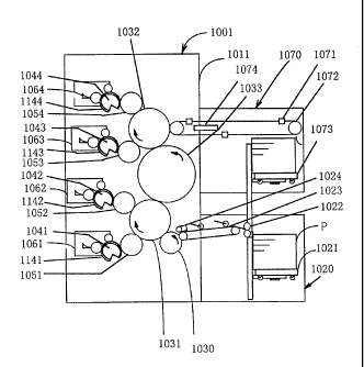
As shown in FIG. 1, a printing apparatus 1001 comprises
a frame body 1011. The frame body 1011 comprises a recording
medium supplying apparatus 1020 of a unit type, a delivery
cylinder 1030, impression cylinders 1031, 1032, a transfer
cylinder 1033, a discharging apparatus 1070, and ink coating
apparatus 1061, 1062, 1063 and 1064. Plate cylinders 1041, 1042,
1043, 1044 each having a printing plate are attached to the ink
coating apparatus 1061, 1062, 1063, 1064, respectively.
Blanket cylinders 1051, 1052, 1053, 1054 are provided to contact
the plate cylinders 1041, 1042, 1043, 1044, respectively. The
paper supplying apparatus 1020 comprises a feeding station 1021,
serving as a stacker for a recording medium, a paper pickup
apparatus 1022, a paper transfer conveyor 1023, serving as a
paper supplying apparatus, a feeding apparatus 1024, which
detects a head of a sheet of paper so as to feed paper to the
delivery cylinder 1030.
The discharging apparatus 1070 comprises a rod 1071, a
chain delivery 1072, a discharge station 1073, and a dryer 1074.
The rod 1071 has a paper holding apparatus for receiving a
printed sheet of recording medium P from the impression cylinder.
The chain delivery 1072 delivers paper to the discharging
station 1073. The discharging station 1073 stacks the printed
recording mediums, rotates horizontally after the end of
printing so as to change the direction by 1800 about the
direction of the normal line of the recording mediums. The
dryer 1074 dries the recording mediums P being delivered by the
chain delivery 1072.
In the printing operation in the printing apparatus 1001
of FIG. 1, the sheets of recording mediums P are dealt by a human
or a machine, and then stacked in good order at a predetermined
position of the feeding station 1021 of FIG. 1. When the
printing apparatus 1001 is actuated, the recording mediums P
CA 02255777 1998-11-23
37
stacked on the feeding station 1021 are separated one by one
by the injection of compressed air from an air nozzle (not shown)
attached to the paper pickup apparatus 1022. Thereafter, the
recording mediums P are sent to the paper transfer conveyor 1023
one by one with a distance by the paper pickup apparatus 1022.
The recording mediums P sent to the paper transfer
conveyor 1023 are fed by feeding apparatus 1024 at timing when
the head position of the recording medium is just adjusted to
the paper holding sections of the delivery cylinder 1030. Then,
the head position is held by the paper holding apparatus of the
delivery cylinder 1030, and delivered to the paper holding
apparatus of the impression cylinder 1031, which rotates in
synchronous with the delivery cylinder 1030.
The delivery cylinder 1030 and the impression cylinder
1031 are formed such that an outer diameter ratio of the cylinder
1030 to the cylinder 1031 is 1 to 2, and the paper holding
sections of the respective cylinders are provided in the
respective cylinders at the above ratio. In other words, one
paper holding section is provided in the delivery cylinder 1030
and tow paper holding sections are provided in the impression
cylinder 1031 (the distance between two paper holding sections
in the cylinder outer peripheral direction is adjusted to the
cylinder outer peripheral length of the delivery cylinder 1030).
The feeding pitch of recording mediums P and that of impression
cylinder 1031 become the same, and paper can be surely delivered
by the paper holding section of the delivery cylinder 1030 and
that of the impression cylinder 1031. Also, the paper holding
sections do not interfere with each other between the cylinders.
In this apparatus, the outer diameter ratio of the cylinder 1030
to the cylinder 1031 is 1 to 2 in order to miniaturize the
printing apparatus.
The recording mediums P whose heads are held by the paper
holding apparatus of the impression cylinder 1031 rotate with
CA 02255777 1998-11-23
38
the impression cylinder 1031. Then, the recording mediums P
are sandwiched by the contact portion between the bracket
cylinder 1051 and the impression cylinder 1031, and the contact
portion between the blanket cylinder 1052 and the impression
cylinder 1031, sequentially, and predetermined pressure is
applied thereto.
At this time, image patterns, in the form of as ink images,
on the printing plates 1141 and 1142, which are wound around
the plate cylinders 1041, 1042, respectively, are transferred
onto the blanket cylinders 1051 and 1052 with color ink supplied
by ink coating apparatus 1061, 1062, respectively. Each ink
image is transferred onto the recording mediums P rotating with
the impression cylinder 1031. The distance from the portion
where the impression cylinder 1031 contacts the blanket
cylinder 1051 to the portion where the impression cylinder 1031
contacts the blanket cylinder 1052 is set to be longer than the
maximum length of the recording mediums P in the direction of
the progress. As a result, there occurs no case in which the
recording mediums P contact two blanket cylinders at the same
t ime .
Thus, ink images of two colors, which are supplied from
the ink coating apparatus 1061 and 1062, respectively, are
transferred onto the recording mediums P on the impression
cylinder 1031. Then, the recording mediums P are carried from
the impression cylinder 1031 to the transfer cylinder 1033
having the same paper holding apparatus as the impression
cylinder 1031.
The impression cylinder 1031 and the transfer cylinder
1033 are formed such that an outer diameter ratio of the cylinder
1031 to the cylinder 1033 is 2 to 3. Then, the paper holding
sections of the respective cylinders are provided in the
respective cylinders at the above ratio, similar to the delivery
cylinder. As a result, the paper holding section of the
CA 02255777 1998-11-23
39
impression cylinder 1031 and that of the transfer cylinder 1033
can deliver the recording mediums P at the same timing. In the
printing apparatus 1001, the outer diameter ratio of 2 to 3,
which can reduce the diameter of the impression cylinder as
small as possible, is set in order that the printing apparatus
is miniaturized and the impression cylinder is manufactured at
a low cost as possible.
A special paper having a large amount of minute particles
is wound around the surface of the transfer cylinder 1033, and
print ink of the ink images transferred onto the recording
mediums P is not transferred onto the surface of the transfer
cylinder 1033.
The recording mediums P thus delivered to the transfer
cylinder 1033 are carried from the transfer cylinder 1033 to
the impression cylinder 1032 having the same shape and the same
paper holding apparatus as the impression cylinder 1031. At
this time, image patterns, in the form of ink images, of printing
plates 1143 and 1144, which are wound around plate cylinders
1043, 1044, respectively, are transferred onto the blanket
cylinders 1053 and 1054 with color ink supplied by ink coating
apparatus 1063, 1064, respectively. Sequentially, ink images
are transferred onto the recording mediums P, which have been
delivered to the impression cylinder 1032 and rotate with the
impression cylinder 1032.
The recording mediums P to which four colors have been
thus transferred are carried from the impression cylinder 1032
to the rod 1071, which is the paper holding member of the chain
delivery 1072. The surfaces of the recording mediums P carried
to the rod 1071 are dried by the simple dryer 1074 such as an
ultra violet ray curing apparatus in the process in which the
recording mediums P are carried to the discharging station 1073
by the chain delivery 1072. This prevents offset of the print
image onto the sheet of paper. The recording mediums P thus
CA 02255777 1998-11-23
carried to the discharging station 1073 by the chain delivery
1072 are stacked, and a series of multicolor printing processes
is ended.
At this time, as being obvious from FIG. 1, the printed
5 surfaces of the recording mediums P are placed at a lower surface
side of the recording mediums P in a state in which the recording
mediums P are stacked on the feeding station 1021. Then, the
printed surfaces of the recording mediums P are placed at an
upper surface side of the recording mediums P in a state in which
10 the recording mediums P are stacked on the discharge station
1073 at the end of printing. Therefore, even when abnormality
such as a print defectiveness occurs during printing, an
operator can confirm the printing result immediately.
In the case where the printing to the back face of the
15 printed sheet is sequentially performed, the feeding station
1021 is detached, the discharging station 1073 is rotated, and
the direction of the sheet is changed at by 1800 horizontally.
Then, the recording mediums P are shifted to the position of
the feeding station 1021 with the discharging station 1073, and
20 the discharging station 1073 is used as the feeding station 1021.
Thereby, the discharging station 1073 can be set to the sheet
feeding position of the recording medium supplying apparatus
1020. Namely, in the printing apparatus 1001, the printing to
the back face can be continuously performed only by installing
25 the empty feeding station 1021 in place of the discharging
station 1073, and complicated movement of the recording mediums
at the duplex printing can be kept to a minimum. The printing
apparatus 1001 can easily carry out the duplex printing having
a good quality even in a small space.
30 In the above embodiment, double-diametered cylinders are
used (the outer peripheral length of the surface around which
the recording medium is wound was twice as large as the plate
cylinder) as the impression cylinders. And as the transfer
CA 02255777 1998-11-23
41
cylinder, triple-diametered cylinder is used. In addition to
such the configuration, waterless plates are used, so that the
dampening water apparatus are omitted. As a result, the ink
coating apparatus can be easily arranged substantially in a
direction of gravity. Note that substantially the same result
can be obtained if the configuration having a triple-diametered
cylinder as the impression cylinders, and a double-diametered
cylinder as the transfer cylinder, are used as shown in FIG.
3. In this case, an outer diameter ratio of the transfer
cylinder 1030 to the impression cylinder 1031 is 1 to 3.
Next, one preferred embodiment of the coating apparatus
and that of the print apparatus of the present invention will
be explained.
The multicolor printing or the duplex printing according
to the present embodiment uses waterless plates. In this
embodiment, there are provided unit -typed ink coating apparatus,
which are small and light and detachable. Each ink coating
apparatus, as shown in FIG. 4, comprises the form roller 1201
having an elastic layer of a single or a multilayer, the doctor
blade 1202, the eccentric cam 1203 for controlling the movement
of the doctor blade, a flattening member 1209, the ink
distributing rollers 1210, 1211, and the auxiliary form roller
1212, serving as an auxiliary coating roller, having an elastic
surface.
The form roller 1201, the doctor blade 1202, the side
plates 1207 and 1208, which are arranged at both sides of the
in the form roller 1201 in its axial direction, and the ink
fountain 1206 form the ink fountain space 1205. The side plates
1207 and 1208 are gently pressed to the form roller 1201 so as
to be sealed. This prevents ink i of the ink fountain space
1205 from being leaked outside.
A small gear (not shown) rotating solidly with the form
roller 1201 is engaged with a large gear (not shown) rotating
CA 02255777 1998-11-23
42
solidly with a plate cylinder 1041. Thus, the form roller 1201
and the plate cylinder 1041 are synchronized with each other
and rotated at the same circumferential speed at their contact
section.
The ink coating apparatus is configured so that the
eccentric cam 1203 attached to the shaft 1204 is rotated so as
to move the doctor blade 1202 back and fourth in a direction
of an arrow A, thereby changes the engagement between the doctor
blade 1202 and the form roller 1201 in order to control the
thickness of the coated ink film formed on the outer periphery
of the form roller 1201.
The surface of the coated ink film, whose thickness has
been controlled, on the form roller 1201 is flattened by the
flattening blade 1209, serving as the flattening member.
The doctor blade 1202 used in this coating apparatus is
made of steel such as Swedish steel having a thickness of 0.1
to 0.5 mm. The doctor blade 1202 is held to be inserted from
the upper and lower sides by the ink fountain 1206 and a lower
face pressing member 1214, thereby forming an ink quantity
controlling member 1221. Thus, it is configured that by
limiting the rotation angle of a motor (not shown) according
to a sensor, which motor is mounted on each of the ink coating
apparatus 1061 to 1064, by controlling its reciprocal rotation
with an electric circuit, and by slightly rotating the eccentric
cam 1203 for controlling the movement of the doctor blade 1202
through the shaft 1204, the engagement quantity of the doctor
blade 1202, which forms the ink quantity controlling member 1221,
to the surface of the form roller 1201 is controlled. As a
result, the thickness of the coated ink film formed on the form
roller 1201 can be controlled.
In the embodiment shown in FIG. 4, the flatting blade 1209
is used as the flatting member, and the flattening member is
made of steel having the thickness of 0. 1 to 0. 5 mm. Also,
CA 02255777 1998-11-23
43
one flattening member is provided at the downstream side of the
doctor blade 1202 to the direction where the form roller 1201
progresses with an interval of several millimeters. The
interval of 1 mm or more is favorable in view of the flattening
effect, and the interval of 10 mm or less is favorable in view
of the miniaturization of the apparatus. Moreover, a favorable
range of the interval is about 1 to 3 mm.
When the flattening member is positioned at the upstream
side of the doctor blade 1202 in the direction where the form
roller 1201 progresses, the striped defects, which have been
generated in the doctor blade portion in the circumferential
direction of the surface of the ink layer because of paper dust
or the like, do not grow and are not so conspicuous. It is
because the surface of the form roller 1201 is once flattened
at the place where the flattening member is set. In particular,
this is useful in the prevention of the striped defects in the
printing pattern, which is uniform to the axial direction of
the roller, such as a solid printing, a screen tint printing,
etc, and in the printing pattern having a small image area such
as rules and characters.
On the other hand, when the flattening member is
positioned at the downstream side of the doctor blade 1202 in
the direction where the form roller 1201 progresses as shown
in FIG. 4, the striped defects, which have been generated in
the doctor blade portion 1202, can be easily made not to be
conspicuous regardless of the image patterns of the printing
plates by the flattening blade 1209 serving as the flattening
member. It is because the film thickness of the ink layer on
the ink form roller 1201 at the flattering blade 1209 is uniform
and substantially as large as at the doctor blade 1202.
Moreover, since the film thickness of the ink layer on the ink
form roller 1201 at the flattering blade is uniform and
substantially as large as at the doctor blade 1202, the
CA 02255777 1998-11-23
44
contacting pressure between the flattening blade 1209 and the
surface of the form roller 1201 can be easily controlled.
Therefore, the attaching position of the flattening member is
favorably set to the downstream side of the doctor blade in the
direction where the form roller 1201 progresses as shown in FIG.
4.
As a favorable example in which the blade is used as the
flattening member as shown in FIG. 4, there is a coating
apparatus as shown in FIG. 5. In the coating apparatus, the
front edge of the leading side of the doctor blade 1202 and that
of the flattening blade 1209, serving as the flattening member
are curved. Moreover, the curvature R of the doctor blade 1202
is the same as the curvature r of the flattening blade 1209 or
more. For example, if the engagement between the surface of
the form roller 1201 and the doctor blade 1202 and between the
surface of the form roller 1201 and the flattening blade 1209
are set to be the same, when the ink layer formed on the surface
of the form roller 1201 passes through the flattening blade 1209,
the ink layer is subjected to resistance by a curvature
difference between the front edges of the leading sides. The
resistance is higher than resistance which is obtained when the
ink layer passes through the doctor blade 1209. Hence, it is
easily to provide a coating apparatus which can easily flatten
the ink layer surface, and which can easily control the
contacting pressure between the surface of the form roller 1201
and the doctor blade 1202 and between the surface of the form
roller 1201 and the flattening blade 1209.
Favorable curvature R of the doctor blade 1202 is 15 m
or more when ordinary waterless ink is used. The curvature R
is varied, depending on degree of elasticity of the form roller
1201, relative speed of the form roller 1201 to the doctor blade
1202, viscosity of ink i, etc, so that a suitable value within
the range of 15 m or more may be selected.
CA 02255777 1998-11-23
As an example, a favorable value of the curvature R is
to 75 m under conditions in which the form roller 1201 is
one layer roller, a surface rubber hardness is 300 of JISA
(corresponding to a durometer A type by Shore), relative
5 velocity to the doctor blade 1202 is 36 m/min., viscosity of
ink i is about 900 poise.
In the explanation hereinafter, the rubber hardness
indicates JISA hardness based on the corresponding durometer
A type by Shore.
10 The important technical concept of the present invention
is to separate two functions, which are conventionally imposed
on the doctor blade, that is, the adjustment of film
pressure ( sic ) of the coated ink film, and the flattening of the
coated ink film surface layer. The function of adjusting ink
15 film pressure(sic) is provided to the doctor blade, and the
function of flatting the coated ink film surface is provided
to the flattening member.
The function of the flattening member is to give suitable
resistance to the surface of an ink layer 1251, as a coated layer,
20 during the movement of the ink layer, thereby flattening the
ink layer surface just like a trowel.
In other words, when the doctor blade portion 1202 is
clogged with paper dust or the like, the form roller 1201 bends
at the clogged portion and escapes therefrom. For this reason,
25 the thickness of the ink layer of this portion increases, and
the circumferential striped defects 1252 as shown in FIG. 6 are
generated in the ink layer with the clogged paper dust or the
like. Then the striped defects 1252 contact the flattening
member, the risen portion of the ink layer is blocked and ink
30 cannot pass thereunder, so that ink is pressed into the groove
portions of the striped defects 1252. The groove portions of
the stripped defects 1252 are filled with ink, and flattened
as shown in FIG. 7.
CA 02255777 1998-11-23
46
The function of the flattening member is as mentioned
above, and any member may be used if the member gives the suitable
resistance to the surface of the ink layer to block the ink layer.
Basically, there is no limitation in the material of the
flattening member, the shape, and the quantity. However, in
consideration of a simpler structure, and an easier adjustment,
it is desirable from the easiness of the manufacture that the
flattening member be shaped to be a blade as shown in FIG. 4,
and that its material be metal such as iron, ceramics, resin,
etc.
Moreover, there is a more preferred embodiment of the
coating apparatus. As shown in FIG. 8, the auxiliary form
rollers 1212, 1213 are provided at the upstream side of the form
roller 1201 and the downstream side thereof to the progress
direction of the printing plate, serving as surface to be coated
by the form roller 1201, respectively. Then, the ink
distributing rollers 1210, 1211 are provided between the form
roller 1201 and the auxiliary form rollers 1212 and 1213. The
ink distributing rollers 1210 and 1211 come in contact with the
form roller 1201 and the auxiliary form rollers 1212 and 1213
at the same time, and oscillate in the axial direction.
According to the above coating apparatus, the ink layer
surface on the form roller 1201 is flattened by the flattening
member, so that the striped defects 1252 are hardly generated
in the circumferential direction of the surface of the coated
ink film by paper dust or the like. Even if the striped defects
are generated, the striped defects become inconspicuous at the
time when the ink layer is transferred onto the printing plate
1141. It is because the phases of the striped defects on the
auxiliary form roller 1213 and the form roller 1201 and the
auxiliary form roller 1213 differ from each other by the
functions of the ink distributing rollers 1210 and 1211
oscillating in the axial direction.
CA 02255777 1998-11-23
47
For example, in the ink coating apparatus as shown in
FIGS. 9 and 10, even if the striped defects are generated in
the portion of the doctor blade 1202, each phase of the striped
defects is axially shifted from the form roller 1201, and
transferred onto the auxiliary form rollers 1212 and 1213 by
the functions of the ink distributing rollers 1210 and 1211
oscillating in the axial direction. For this reason, the ink
coating on the printing plate 1141 using each of the auxiliary
form roller 1213, the form roller 1201, and the auxiliary form
roller 1212 is performed in the state that the phase is axially
shifted. As a result, the striped defects become inconspicuous
on the printing plate 1141 serving as the coating surface.
The form roller 1201 used in this coating apparatus
comprises, for example, a rubber or plastic elastomeric roller
having an elastic surface. The structure of the elastic portion
of the roller may be one layer. Preferably, a multilayer
structure having two or more layers in which its hardness
becomes higher than an inner layer as approaching to the surface
layer may be used as shown in FIGS. 4, 8, 9, 11, and 12 since
the generation of the striped defects can be reduced.
In this type of coating apparatus, the thickness of the
coated ink film is controlled by only the change in the
engagement between the doctor blade 1202 and the form roller
1201. If, for example, a rubber like nitrile rubber is used
as material of the form roller 1201, the thickness of the coated
ink film is changed by wear of the roller surface or plasticizer
in the rubber is extracted and the surface hardness of the roller
becomes 100 or more higher than an initial setting value when
such a roller is used for a long period of time. As a result,
there occurs a problem in which the striped defects are
frequently generated because of paper dust.
For that reason, the form roller 1201 having the
multilayer structure in which the hardness of the surface layer
CA 02255777 1998-11-23
48
is set higher than that of the inner layer may be preferably
used. Preferably, the uppermost surface layer is at least
polyurethane rubber, and more preferably the respective layers
may be polyurethane rubber.
Here, the condition "the hardness of the surface layer
is set higher than that of the inner layer" includes the
following cases. Namely, attention is paid to the adjacent two
layers, and the relationship in which the hardness of the layer
close to the surface is higher than that of the layer close to
the interior is established in all adjacent two layers as a more
favorable configuration. The above condition is not limited
to the above-mentioned case. The above condition also means
that the average hardness of the surface layer, which is
obtained when the multilayer of rubber is divided into two
halves in the radial direction, is higher than the average
hardness of the inner layer (the average hardness is a value
obtained when the total sum, which is obtained by multiplying
hardness of each layer by the thickness, is divided by the total
thickness). Therefore, even if the rubber layer does not have
a definite layer structure, the above condition is satisfied
in the case in which the above relationship is established when
the layer is divided into two in view of the above point.
The reason why polyurethane rubber is used is as follows :
Polyurethane rubber is rich in elasticity and toughness,
and has high tear strength and good abrasion resistance. Due
to this, polyurethane rubber has a good dimensional stability
at the time of friction between the form roller and the doctor
blade, so that the thickness of the coated ink film can be
maintained constant. Also, polyurethane rubber has a
considerable low content of plasticizer as compared with
nitrile rubber or the like, which is generally used in the
printing apparatus. The change of the rubber hardness, which
is caused when plasticizer in rubber is extracted, is small.
CA 02255777 1998-11-23
49
Moreover, by use of the multilayer in which the hardness of the
surface layer is set higher than that of the inner layer,
polyurethane rubber can largely reduce the striped defects due
to paper dust as compared with the single layer.
If all layers are formed of polyurethane rubber, abrasion
of the roller surface is small. As a result, the change in the
thickness of the coated ink film is low even if the roller is
used for a long period of time. By use of the multilayer in
which the hardness of the surface layer is set higher than that
of the inner layer, the generation of the striped defects due
to paper dust is low, and plasticizer in rubber is not extracted,
so that the change in the rubber hardness is small. Therefore,
the use of polyurethane rubber is favorable since good coating
conditions can be maintained for a long period time.
In the above-mentioned ink unit, since the form roller
1201 and the doctor blade 1202 rub on each other through the
ink layer, the form roller 1201 is easily worn. The wear of
the form roller 1201 increases as the surface hardness of the
form roller 1201 decreases. Also, the quantity of heat at the
portion of the form roller 1201 increases, and ink temperature
rises, with the result that they have an unfavorable influence
on the printing conditions. In the single layer of polyurethane
rubber had a disadvantage in which the surface hardness of the
form roller could not be highly increased because of the
limitation of hardness. In contrast, when the form roller is
formed of the multilayer structure, the condition in which no
striped defects are generated can be prepared by reducing the
hardness of the inner layer even if the surface hardness of the
uppermost layer is set to 500 or more, which cannot be used
in the single layer. As a result, the form roller can be used
without any problem.
In the form roller 1201 of polyurethane rubber, it is
required that the engagement with the doctor blade 1202 be
CA 02255777 1998-11-23
maintained constant. For this reason, there is favorably used
an elastic structure in which the form roller is immediately
returned to the original state from the deformed state. A
foaming structure, which needs much time to return to the
5 original state from the deformed state, is not favorable.
The present invention obtained the above-mentioned good
advantages by using the polyurethane rubber of the multilayer
structure, which was conventionally difficult to be
manufactured.
10 As polyurethane rubbers that can be used in the present
invention, there are UV Summit by Meiwa Rubber Industrial Co.,
Ltd, Uron H by Kinyousha Co., Ltd, New UV by Kanuki Roller Works,
Col, Ltd, etc.
In a case where the form roller 1201 having the single
15 structure of rubber or plastic elastomer is used, the surface
hardness of the form roller 1201 is preferably set to 150 to
700 based on the rubber hardness defined by JISA
(corresponding to a durometer A type by Shore). It is because
it is difficult to form a thin ink film if the hardness is below
20 150 . Also, a stable ink film can neither be obtained and normal
ink transfer to the plate surface can nor be performed if the
hardness exceeds 700 .
The favorable value of the hardness is 250 to 50(' . The
reason is as follows:
25 Specifically, if the surface hardness of the form roller
1201 is low, a frictional heat between the form roller 1201 and
the doctor blade 1202 pressure contacted to the form roller 1201
during the printing is largely generated. By this influence,
the form roller 1201 is thermally expanded, a difference in
30 peripheral speed between the form roller 1201 and the plate
cylinders occurs and a slip is induced, and the blanket
cylinders easily become dirty. The favorable value of the
surface hardness of the form roller 1201, which can avoid the
CA 02255777 1998-11-23
51
above problem, is 40' to 50' .
On the other hand, when the form roller 1201 having the
multilayer structure of rubber or plastic elastomer is used,
the stable ink film can be obtained by reducing the hardness
of the inner layer even if the surface hardness exceeds 700 .
There is no problem as long as the surface hardness does not
become too low. Therefore, the favorable value of the hardness
of the outermost layer of the form roller 1201 is 400 or more.
Next, the following will explain a favorable embodiment
of each of the imaging apparatus of the present invention, the
imaging method, the imaging medium, the printing system, the
printing apparatus, and the printing method with reference to
the drawings.
FIG. 13 shows a perspective view of one embodiment of the
imaging apparatus of the present invention. As shown in FIG.
13, an imaging apparatus 2001 comprises a plate cylinder 2011,
serving as a medium support drum for winding an imaging medium
2018 around its outer surface, an imaging head 2012 including
a beam irradiation source and an optical system for focusing
beams emitted from the beam irradiation source, a control unit
2016 for controlling the beam irradiation source, and a cable
2015 for connecting the imaging head 2012 and the control unit
2016 to each other.
The imaging head 2012 is fixed onto a linear stage 2014
for realizing a parallel movement to an axial direction of the
plate cylinder 2011. The distance between the imaging head 2012
and the imaging medium 2018 is controlled such that the beams
are focused on the surface of the imaging medium. The output
of the beam irradiation source is controlled based on a value
of a laser power detector 2017. More specifically, the output
of the beam irradiation source is controlled in order to
sufficiently generate the change in the physical properties
such as physical projections and depressions or the change in
CA 02255777 1998-11-23
52
solubility to solvent at a beam irradiated section and non-
radiated section of the imaging medium 2018.
Then, when the imaging of the print pattern is executed,
the plate cylinder 2011 around which the imaging medium 2018
is wound is rotated in a direction of an arrow R of the figure
directly by use of a drive motor 2013 such as a pulse motor or
through a change gear. In addition, the beam irradiation source
is switched according to imaging data as moving the imaging head
2012 fixed onto the linear stage 2014 in a direction of an arrow
S parallel to the shaft of the plate cylinder in the figure.
Thereby, the printing(sic) apparatus 2001 generates the change
in the physical properties such as physical concave and convex
portions or the change in solubility to solvent on the surface
of the imaging medium 2018 according to two dimentional imaging
data.
In the imaging apparatus 2001, the use of a plurality of
beam irradiation sources, which can drive independently, can
be considered to improve the performance. In this case, the
improvement of the performance of the imaging apparatus 2001
means improvement of imaging speed and resolution, and a
trade-off relationship is established between the imaging speed
and the resolution.
The resolution in this case shows how many dots can be
formed per unit length, and dpi (dots per inch) is generally
used as a unit. For example, 2540 dpi corresponds to 100
dots/mm.
Suppose that i lines continuous to a fast scan direction
emitted simultaneously from i beam irradiation sources are
imaged using the imaging head 2012 having i beam irradiation
sources.
In this case, dot pitches dp for achieving a predetermined
resolution r are 1/r. A direction R of lines imaged by the
rotation of the plate cylinder 2011, is defined as a fast scan
CA 02255777 1998-11-23
53
direction, and a direction S of lines imaged by the parallel
movement of the imaging head 2012 is defined as a slow scan
direction. The imaging head is shifted in the slow scan
direction by a predetermined distance after finishing the
imaging corresponding to one revolution in the fast scan
direction. The predetermined distance is i times as large as
the dot pitch dp on the imaging medium. Thereafter, next i lines
are imaged, and a series of operations is repeated so that the
imaging of the entire imaging area is finished.
Thus, by use of i beam irradiation sources, time required
for imaging can be reduced to 1/i when the resolution is the
same. In order to increase the resolution j times, it is needed
that the dot pitch be set to dP/ j and that the distance of the
movement of the imaging head be set to dp X i/j. Then, time
required for imaging results in j/i times.
There is a laser diode array as one of methods using a
plurality of beam irradiation sources. The general outline
view is shown in FIG. 14.
A laser diode array 2008 includes eight laser diodes,
which are capable of driving independently, in one chip. Laser
beam emission ends 2081a to 2081h, drive side electrodes 2082a
to 2082h, a rear face common electrode 2083 common to all laser
diodes are provided to the eight diodes, respectively. A
predetermined current to the drive side electrodes 2082a to
2082h allows the laser beam to be emitted from the corresponding
laser beam emission ends 2081a to 2081h. In this case, the
predetermined current means a current value more than a
threshold value at which the laser diode starts to generate a
laser beam.
There is a fiber array as one of another methods using
a plurality of beam irradiation sources. The outline view of
a laser apparatus 2006 for a fiber output is shown in FIG. 15.
The laser apparatus 2006 comprises a package section 2061
CA 02255777 1998-11-23
54
~
and an optical fiber 2062 for guiding a laser beam to an outer
unit. The package section 2061 comprises a laser diode chip
having at least one light-emission end, a conductive member for
an electrical contact between an electrode of the diode chip
and the outer unit, a heat conduction member for radiating heat
from the diode chip to the outer unit, and an optical system
for making the laser beam being incident onto the optical fiber
from the laser diode. Then, the laser beam is emitted from an
emission end 2063 of the optical fiber 2062.
The emission end 2063 of the optical fiber 2062 shown in
FIG. 16 has a core portion 2064 and a clad portion 2065, and
the laser beam is emitted from the core portion 2064. Then,
the emission ends 2063 of the plurality of fibers of the laser
apparatus for the fiber output are arranged in an array form
and fixed to form the fiber array. When the fiber array is used
as the beam irradiation source, the minimum distance between
the beam irradiation sources is restricted by an outside
dimension of the clad portion 2065.
In many cases, it is impossible to arrange the beam
irradiation sources, that are the respective emission ends, to
be close to each other without any space in either of the methods
of the laser diode array and the fiber array. In order to
perform the imaging in the imaging area of the imaging medium
without any space, the array must be inclined to the slow scan
direction S by a predetermined angle 0 as shown in FIG. 17. An
array 2007 comprises eight beam irradiation sources 2071a to
2071h, and its inclination angle 0 is defined by the following
equation (1).
cos 0 = ds/a . Eq. (1)
where a is the interval between the beam irradiation sources,
a dot pitch at light source surface ds that is obtained by
converting the dot center pitch corresponding to the
predetermined resolution in the slow scan direction S to the
CA 02255777 1998-11-23
dimension on the beam irradiation source surface, which is
obtained by dividing the medium surface dot pitch dP by the
magnification of the optical system. For example, when the
resolution is 2540 dpi, i.e, dP = 10 m and the magnification
5 of the optical system is 1/4, d9 = 40 Eun is met.
In order to improve the quality of printing in the
multicolor printing, it is obviously important to improve the
position accuracy of the dots on the imaging medium imaged by
the imaging apparatus having a single head or a plurality of
10 imaging heads. It is also obviously important to align the
imaging start position of the imaging medium for each color.
In other words, if the imaging medium is directly imaged without
using the intermediate member and the imaging start position
of the imaging medium is set to the same position, a minute
15 positional shift of the printing pattern of the imaging medium
of each color in the multicolor printing can be can be reduced,
which is effective means for improving the quality of multicolor
printing without taking much time.
Conventionally, sharing of the positioning method, the
20 attaching method, and components were not conducted between the
imaging apparatus and the printing apparatus for the following
reasons: 1) the direct imaging to the imaging medium was not
often performed, 2) there was few common items in the technical
concept in manufacturing the apparatus, e.g., the imaging
25 apparatus aimed to obtain weight reduction while the printing
apparatus aimed to increase strength to obtain high quality of
printing, 3) generally, the manufacturers are not the same in
the imaging apparatus and the printing apparatus.
Even these days when immediate preparation of the imaging
30 medium by the imaging apparatus is frequently done, the
above-mentioned sharing has not been conducted.
The feature of the printing system of the present
CA 02255777 1998-11-23
56
invention lies in the point that the positioning method of the
imaging medium in the printing apparatus is substantially the
same as used the imaging apparatus. For example, in the imaging
apparatus in which the positioning holes are provided in the
imaging medium and the printing pattern is directly formed on
the imaging medium with the energy beam with reference to the
positioning holes, the plate cylinder used in the printing
apparatus is provided as the attaching member of the imaging
medium. Thereby, the reference attaching position of the
imaging medium to the imaging apparatus and the reference
attaching position to the printing apparatus are set to be the
same as each other.
In this way, the minute positional shift, which is caused
by the difference in the reference attaching position of the
imaging medium between the respective apparatus, is eliminated.
Moreover, the minute positional shift, which is caused by the
curvature specific to the plate cylinders of both apparatus and
the habit of the apparatus caused at the time of winding the
imaging medium, can be minimized. As a result, the designing
and manufacturing cost is reduced by sharing the plate cylinders.
Thereby, the printing apparatus and the imaging apparatus are
structured at reasonable cost.
Even in a case where the complete sharing with the plate
cylinders of the printing apparatus cannot be executed due to
weight reduction of the plate cylinders of the imaging apparatus,
the structure of the imaging medium attaching section may be
shared. Thus, the minute positional shift, which is caused by
the difference in the reference attaching position of the
imaging medium between the respective apparatus, can be
minimized. Also, the minute positional shift, which is caused
by the curvature peculiar to the plate cylinders of each
apparatus and the habit of the apparatus caused at the time of
winding the imaging medium, can be minimized. Therefore, it is
CA 02255777 1998-11-23
57
obvious that the high quality printing in which the positional
shift of the similar imaging mediums is small can be carried
out as well as the case of the sharing of the plate cylinders.
FIG. 18 shows an example of the imaging medium in the case
where the positioning method of the imaging medium in the
printing system of the present invention is carried out by
engaging positioning holes provided in the imaging medium with
positing pins provided in the imaging apparatus. FIG. 13 is
a perspective view of the imaging apparatus relating to this
case.
As shown in FIG. 18, an imaging medium 1018A has a
plurality of positioning holes 2181 at the imaging medium head
portion and attaching holes 2182 at the imaging medium bottom
portion. In the plurality of positioning holes 2181 and the
attaching holes 2182, the imaging medium is cut such that two
sides, having at least one of two sides along the feeding
direction to the plate cylinder and a head side of the imaging
medium, intersect at right angles at the time of preparing the
imaging medium 2018A. Thereafter, the positioning holes 2181
and the attaching holes 2182 are correctly processed to
predetermined shapes by a special-purpose processing machine
based on the two sides intersecting at right angles. In the
plate making and the printing, the reference attaching position
of the imaging medium is set to the plurality of positioning
holes 2181. Two sides, that is, the side, serving as a reference
of holing, and the head side of the imaging medium, do not
necessarily intersect at right angles. However, two sides
preferably intersect at right angles since workability
increases in the cutting process of the imaging medium, the
holing process of the positioning holes 2181, and the packing
process of the imaging medium.
The engagement of the positioning holes 2181 provided in
the imaging medium with the positioning pins provided in the
CA 02255777 1998-11-23
58
,
imaging apparatus will be explained as follows. That is, for
use of a resin film as the base material of the imaging medium,
when the opening diameter of each of the positioning holes of
the imaging medium is larger than the outer diameter of each
of the positioning pins, the difference between the opening
diameter and the outer diameter are smaller than the dot pitch.
On the other hand, when the opening diameter of each of the
positioning holes of the imaging medium is smaller than the
outer diameter of each of the positioning pins, the positioning
is preferably set to a range in which the positioning holes
provided in the resin film are not broken.
The reason will be explained as follows. That is, for
use of the resin film as the base material of the imaging medium,
even if the outer diameter of each of the positioning pins is
larger than each of the opening diameters of the positioning
holes 2181, the resin film is elastically deformed and the
positioning pins are fitted to the positioning holes. As a
result, a good positioning can be made without breaking the
positioning holes. However, when the outer diameter of each
of the positioning pins is smaller than each of the opening
diameters of the positioning holes 2181, the positioning
accuracy worsens by a space between the positioning holes 2181
and the positioning pins.
For use of metal as the base material of the imaging medium,
the opening diameter of each of the positioning holes 2181
provided in the imaging medium is preferably larger than the
outer diameter of each of the positioning pins. And, the
difference between the opening diameters and the outer
diameters is preferably smaller than the dot pitch.
The reason will be explained as follows. That is, for
use of metal as the base material of the imaging medium, when
the outer diameter of each of the positioning pins is larger
than the opening diameter of each of the positioning holes, the
CA 02255777 1998-11-23
59
positioning holes are broken and the positioning accuracy
worsens. When the outer diameter of each of the positioning
pins is much smaller than the opening diameter of each of the
positioning holes, the positioning accuracy worsens by the
space between the positioning holes and the positioning pins.
An operation of attaching/detaching the imaging medium
to/from the imaging apparatus in this embodiment will be
explained as follows:
FIG. 19 shows the state in which the imaging medium 2018A
is attached to a plate cylinder 2011A in the imaging apparatus
2001 of FIG. 13.
The imaging medium 2018A mounted on a stocker (not shown)
is fed to the plate cylinder 2011A by a feeding roller 2026.
The plate cylinder 2011A has the same structure as the pin-
attaching typed plate cylinder of the printing apparatus. The
plate cylinder 2011A comprises a shaft 2020, a pin row 2023 for
positioning, a head portion fixing claw 2022, and a bottom
portion fixing claw 2025. The shaft 2020 holds the plate
cylinder 2011A to be rotatable, and serves as a center of
rotation. The pin row 2023 for positioning is axially arranged
to be engaged with the positioning holes of the head portion
of the imaging medium 2018A. The head portion fixing claw 2022
is a member for fixing the head portion of the imaging medium
2018A in a state that a shaft 2021 is a center of rotation. The
bottom portion fixing claw 2025 is a member for fixing the bottom
portion of the imaging medium 2018A in a state that a shaft 2024
is a center of rotation and for applying tension to the imaging
medium 2018A so as to eliminate looseness of the imaging medium.
In order to maintain the phase of the plate cylinder 2011A
at the plate cylinder stopping time, a sensor (not shown)
detects the phase to control a drive motor 2013, thereby
controlling the stopping position. The imaging medium 2018A
sent to the plate cylinder 2011A stopped at a predetermined
CA 02255777 1998-11-23
position is stopped to be fed by a feed roller 2026 for feeding
the imaging medium by a signal from a position detecting sensor
(not shown) for detecting the head position of the imaging
medium 2018A. Also, the imaging medium 2018A is positioned by
5 engaging the positioning holes 2181 with the pin row 2023 when
the head fixing claw 2022 actuates in accordance with the signal
from the position detecting sensor and rotates anticlockwise.
A pressing force is applied to the pin row 2023 through
the shaft 2021 having the head fixing claw 2022 by a spring,
10 etc. As a result, the imaging medium 2018A whose head portion
is positioned is surely held on the plate cylinder 2011A.
Thereafter, the plate cylinder 2011A is rotated by the drive
motor 2013 at considerable low speed less than 1/10 of the
peripheral speed of 2 to 10 m/sec at which the imaging operation
15 is executed. Also, the imaging medium 2018A is wound around
the plate cylinder 2011A as being fed by the feeding roller 2026
at the same peripheral speed as the plate cylinder 2011A.
The portion of intersection between the pin row 2023 and
the outer periphery of the plate cylinder 2011A is finished such
20 that no flaws are formed on the imaging medium 2018A at the
attaching time and no looseness is generated in the imaging
medium 2018A. More specifically, the portion of intersection
between the pin row 2023 and the outer periphery of the plate
cylinder 2011A is finished to have a smooth curvature r with
25 a radius of about 15 mm along the peripheral direction of the
plate cylinder 2011A. As a result, the flaws are not easily
formed on the imaging medium at the winding time.
A pressing roller 2027 is placed around the plate cylinder
2011A. The pressing roller 2027 comprises a metal shaft having
30 a plurality of rollers formed of soft and elastic material such
as rubber sponge . The pressing roller 2027 is freely rotatable,
and has a touching/detouching mechanism to/from the plate
cylinder 2011A. Also, when the plate cylinder 2011A rotates,
CA 02255777 1998-11-23
61
the roller 2027 is rotated while engaged such that no looseness
is generated in the imaging medium 2018A wound around the plate
cylinder 2011A.
The plurality of rollers of the pressing roller 2027, the
head portion fixing claw 2022, and the bottom portion fixing
claw 2025 are arranged to be axially shifted such that the
rollers and the claws do not collide with each other.
At the time when the imaging medium bottom portion of the
imaging medium 2018A passes through the pressing roller 2027
by the rotation of the plate cylinder 2011A, the bottom portion
attaching claw 2025 is driven by a cam (not shown) and rotates
about the shaft 2024 in a B direction. Tension is applied to
the imaging medium 2018A by the spring through the bottom
portion fixing claw 2025 inserted to a attaching hole 2128 of
the bottom portion. Also, the pressing roller 2027 is separated
from the plate cylinder 2011A by the connecting/separating
mechanism. In this way, the attaching operation of the imaging
medium 2018A is ended.
A register mark 2028 is provided on the plate cylinder
2011A as shown in FIG. 13, and a register mark detecting
apparatus 2019 provided on the imaging head 2012 reads the
register mark 2028. Thereby, the imaging apparatus 2001
confirms the positional relationship between the imaging head
2012 and the plate cylinder 2011A, and starts imaging. The
position of the imaging medium 2018A attached to the plate
cylinder 2011A is maintained by the pin row 2023.
When the imaging is started at a predetermined position
by the imaging head 2012 as controlling and driving the plate
cylinder 2011A at a fixed peripheral speed, the printing pattern
is formed at a determined position on the imaging medium 2018A.
Therefore, in the multicolor printing, the minute position
shift of the imaging pattern of the imaging medium of each color
can be minimized and the imaging medium having high position
CA 02255777 1998-11-23
62
accuracy can be created without taking much time.
The engagement of the positioning holes 2181 provided
in the imaging medium 2018A with the positioning pins 2023
provided in the imaging apparatus 2001 will be explained as
follows. That is, for use of the resin film as the base material
of the imaging medium 2018A, when the opening diameter of each
of the positioning holes 2181 of the imaging medium is larger
than the outer diameter of each the positioning pins, the
difference between the opening diameters and the outer
diameters is smaller than the dot pitch. On the other hand,
when the opening diameter of each of the positioning holes 2181
is smaller than each of the outer diameters of the positioning
pins, the positioning is preferably set to a range in which the
positioning holes 2181 provided in the resin film are not
broken.
For use of metal as the base material of the imaging medium,
as mentioned above, the engagement of the positioning holes 2182
provided in the imaging medium with the positioning pins are
preferably set such that the opening diameter of each of the
positioning holes 2181 is larger than the outer diameter of each
of the positioning pins and that the difference between the
opening diameters and the outer diameters is smaller than the
dot pitch.
In order to satisfy the above condition, at least one of
the size, the arrangement, and the shape in the positioning
holes and the positioning pins may be changed at each of the
cases when the imaging medium is the resin film and when the
imaging medium is the metal.
For example, it is assumed that the pin diameter of the
pin row 2023 of the plate cylinder 2011A is the same as in the
case when the imaging medium is the resin film and the case when
the imaging medium is the metal. When the base material is the
resin film, the diameter of each of the positioning holes 2181
CA 02255777 1998-11-23
63
provided in the imaging medium is larger than that of the
positioning pins and the difference between the positioning
pins and the positioning holes is smaller than the dot pitch.
Or, the diameters of the positioning holes may be smaller than
those of the positioning pins in the range where the positioning
holes are not broken. When the base material is the metal, the
diameters of the positioning holes may be larger than those of
the positioning pins, and the difference between the
positioning pins and the positioning holes may smaller than the
dot pitch.
As another example, it is assumed that the diameters of
the positioning holes 2181 are the same as in the case when the
resin film is used as the base material of the imaging medium
and in the case when the metal is used as the base material.
When the base material is the resin film, the pin diameters of
the pin row 2023 of the plate cylinder 2011A are smaller than
those of the positioning holes and the difference between the
positioning pins and the positioning holes is smaller than the
dot pitch. Or, the diameters of the positing pins may be larger
than those of the positioning holes in the range where the
positioning holes are not broken. When the base material- is
the metal, the diameters of the positioning pins may be larger
than those of the positioning holes and the difference between
the positioning pins and the positioning holes may be smaller
than the dot pitch.
In this case, a half of the pins of the pin row 2023 may
be used for the film and the other half may be used for the metal.
As the method for arranging the pins of the pin row 2023, there
is a method in which the pins of both ends are used for the film
and the inner pins are used for the metal, and the further inner
pins are used for the film in order. Or, there is a method in
the pins for the film and the pins for the metal are arranged
in a staggered form. To sum up, the same effect can be obtained
CA 02255777 1998-11-23
64
by either method unless the pins for the film and the pins for
metal are arranged in the same phase in the circumferential
direction.
Also, as another method, the pin shapes of the pin row
2023 provided in the plate cylinder 2011A are differently formed
such as circles and squares in each of the cases when the imaging
medium base material is the film and when the imaging medium
base material is the metal. The holes of the imaging medium
placed at the positions where no pins are used for positioning
may be sufficiently enlarged with respect to the pins.
According to the present invention, the holes with the diameter
of 5 to 4. 995 mm were formed in the imaging medium of the film
base material with respect to the pins having the diameter of
5 to 4.995 mm.
As mentioned above, at least one of the sizes, the
arrangement, and the shapes in the positioning holes and the
positioning pins, which are used for positioning the imaging
medium 2018A in the imaging apparatus 2001, may be changed in
each of the cases when the imaging medium is the resin film and
when the imaging medium is the metal. In the method other than
the above-mentioned methods, it is obvious that the same effect
can be obtained if two or more of the size, the arrangement,
and the shape in the positioning holes and the positioning pins
are changed.
Next, the example of the imaging apparatus using the
imaging medium with no positioning holes will be explained with
reference to FIGS. 20 and 21.
As shown in FIG. 20, after preparing an imaging medium
2018B having the two sides along the feeding direction to the
plate cylinder, one of which intersects with the head side of
the imaging medium at right angles, the imaging medium 2018B
is attached to the stocker (not shown). Then, the imaging
medium 2018B is fed to a plate cylinder 2011B by the feeding
CA 02255777 1998-11-23
roller 2026.
The plate cylinder 2011B has the same structure as the
plate cylinder of the printing apparatus of the system in which
the imaging medium is fixed by the griping claw. Specifically,
5 the plate cylinder 2011B comprises a shaft 2031(sic), a
projection 2033 for positioning in the circumferential
direction, a projection 2039 for positioning in the axial
direction, a gripping claw 2032, and a suction hole 2037. The
shaft 2031( sic ) holds the plate cylinder 2011B to be rotatable,
10 and serves as a center of rotation. The projection 2033 abuts
against the side of the head portion of the imaging medium 2018B
to be positioned in the circumferential direction. The
gripping claw 2032 fixes the head portion of the imaging medium.
The suction hole 2037 fixes the bottom portion of the imaging
15 medium by vacuum suction.
In the above case, a portion ranging from a portion close
to a point where two sides of the imaging medium intersect at
right angles to the side of the medium head portion corresponds
to the abutting portion of the imaging medium processed to the
20 predetermined shape in the present invention. Note that the
respective sides do not necessarily intersect at right angles
as far as they are formed to the predetermined shapes.
In order to maintain the phase of the plate cylinder 2011B
at the plate cylinder stopping time, a sensor (not shown)
25 detects the phase to control the drive motor 2013, thereby
controlling the stopping position. The imaging medium 2018B,
which is sent to the plate cylinder 2011B stopped at a
predetermined position, is stopped to be fed by the feed roller
2026 by a signal from a position detecting sensor (not shown)
30 of the imaging medium head position. Also, the imaging medium
2018B is positioned by abutting the respective sides of the
imaging medium 2018b against the projection 2033 for
positioning circumferentially and the projection 2039 for
CA 02255777 1998-11-23
66
positioning axially.
A pressing force is applied to the head portion fixing
claw 2022 through the shaft 2031 by a spring, etc, thereby the
imaging medium 2018B whose head portion is positioned is surely
held on the plate cylinder 2011B. Thereafter, the plate
cylinder 2011B is rotated by the drive motor 2013 at
considerable low speed less than 1/10 of the peripheral speed
of 2 to 10 m/sec at which the imaging operation is executed.
Also, the imaging medium 2018B is wound around the plate
cylinder 2011B as being fed by the feeding roller 2026 at the
same peripheral speed as the plate cylinder 2011B.
A point of intersection between the circumferential
positioning portion and the outer periphery of the plate
cylinder 2011B is finished such that no flaws are formed on the
imaging medium 2018B at the attaching time and no looseness is
generated in the imaging medium 2018B, i.e., the point of
intersection between the circumferential positioning portion
and the outer periphery of the plate cylinder 2011B is finished
to have a smooth curvature r of about 15 mm along the peripheral
direction of the plate cylinder 2011B. As a result, the flaws
are not easily formed on the imaging medium when the imaging
medium is wound around the plate cylinder.
The pressing roller 2027 is placed around the plate
cylinder 2011B. The pressing roller 2027 comprises a metal
shaft having a plurality of rollers formed of soft and elastic
material such as rubber sponge. The pressing roller 2027 is
freely rotatable, and has a connecting/separating mechanism
to/from the plate cylinder 2011B.
Also, when the plate cylinder 2011B rotates, the roller
2027 is pressingly rotated such that no looseness is generated
in the imaging medium 2018B wound around the plate cylinder
2011B.
The plurality of rollers of the pressing roller 2027 and
CA 02255777 1998-11-23
67
the head portion fixing claw 2022 are arranged to be axially
shif ted such that the rollers and the fixing claws do not collide
with each other.
The suction is started through a hole 2036 from a vacuum
suction hole 2038 by a suction apparatus (not shown) at the same
time with starting the rotation of the plate cylinder 2011B.
Then, the imaging medium 2018B wound around the plate cylinder
2011B is sucked and fixed from an imaging medium suction hole
2037 through a space 2030 surround with a side plate of the plate
cylinder 2011B, and bulkheads 2034, 2035. Then, at the time
when the bottom portion of the imaging medium 2018B passes
through the pressing roller 2027, the pressing roller 2027
releases the engagement to the plate cylinder 2011B and
separates therefrom, thereby the attaching operation to the
imaging medium 2018B is ended.
As shown in FIG. 21, a register mark 2028 is provided on
the plate cylinder 2011B, and the register mark 2028 is read
by a register mark detecting apparatus 2019 formed on the
imaging head 2012. Thereby, the positional relationship
between the imaging head 2012 and the plate cylinder 2011B is
confirmed, and the imaging is started. The attaching position
of the imaging medium 2018B attached to the plate cylinder 2011B
is maintained by abutting the end surface of the imaging medium
2018B against the projection 2033 for positioning
circumferentially and the projection 2039 for positioning
axially. Therefore, if the imaging is started at the
predetermined position by the imaging head 2012 as controlling
and driving the plate cylinder 2011B at a fixed peripheral speed,
the printing pattern is prepared at the predetermined position
on the imaging medium 2018B.
As a result, it is possible to minimize the minute
positional shift of the printing pattern of the imaging medium
of each color in the multicolor printing. Then, the imaging
CA 02255777 1998-11-23
68
medium with high positional accuracy can be prepared without
taking much time.
The following will explain another method for correctly
preparing the printing pattern at the predetermined position
on the imaging medium 2018. The following process is carried
out before the imaging medium 2018 is attached to the imaging
apparatus 2001 to image the print pattern. As shown in FIG.
21, the positions of a plurality of register marks 2028P
(register holes for positioning is possible) formed on the
imaging medium 2018 in advance are detected from the imaging
head by a register detecting apparatus 2019 provided at the
predetermined position. Thus, the position of the imaging
medium 2018 in the circumferential direction and that of the
imaging medium 2018 in the axial direction are detected.
Thereafter, the imaging is started at the predetermined
position by the imaging head 2012 based on the detected
circumferential and axial positions of the imaging medium 2018
as controlling and driving the plate cylinder 2011 at the fixed
peripheral speed. As a result, the printing pattern is prepared
at the correct position on the imaging medium 2018. Then, it
is possible to minimize the minute positional shift of the
printing pattern of the imaging medium for each color in the
multicolor printing. Also, the imaging medium with high
positional accuracy can be prepared without taking much time.
The method using the register marks formed on the imaging medium
may be supplementally used to improve the accuracy of the
abutting method shown in FIGS. 20 and 21.
According to the method in which a plurality of register
marks formed on the imaging medium 2018 in advance or a plurality
of register pin hole positions are used as a reference for
imaging, the imaging medium is not necessarily formed to have
the rectangular outline. Also, an imaging medium having the
two sides along the feeding direction to the plate cylinder,
CA 02255777 1998-11-23
69
one of which intersects with the head side of the imaging medium
at right angles, and it can be easily inferred that even in this
case the imaging medium with high position accuracy can be
obtained by executing the imaging medium cutting process and
the holing processing based on the plurality of register marks
in a post-process. However, the two sides preferably intersect
at right angles since workability increases in the imaging
medium cutting process and the holing process of the positioning
holes 2181, and the imaging medium packing process.
Next, the imaging medium is detached from the plate
cylinder of the imaging apparatus as follows.
For instance, in the case of the apparatus shown in FIG.
20, the rotation of the plate cylinder 2011B is stopped after
the imaging of the printing pattern is ended as shown in FIG.
22. Thereafter, the plate cylinder 2011B is rotated in the
direction opposite to the case of the imaging time by the driving
motor 2013.
At this time, the plate cylinder 2011B is rotated at
considerable low speed less than 1/10 of the peripheral speed
of 2 to 10 m/sec at which the imaging operation is executed in
order that no flaws are formed on the imaging medium 2018. At
the same time with the rotation of the plate cylinder 2011B,
the imaging medium 2018 is sequentially separated from the plate
cylinder 2011B by a separation claw 2041 for separating the
imaging medium 2018. The separation claw 2041 has the
touching/detouching mechanism to/from the plate cylinder 2011B
around a shaft 2042. Then, the imaging medium 2018 is
discharged by an image medium discharge roller 2043 whose
peripheral speed is the same as the plate cylinder 2011B.
The head portion fixing claw 2022 by which the head
portion of the imaging medium 2018 is fixed is rotated by a cam
(not shown) and releases the imaging medium 2018B before
reaching the separation claw 2041. As a result, the imaging
CA 02255777 1998-11-23
medium 2018B is smoothly discharged by the plate cylinder 2011B
so as to be sent to a post-process. This operation is not
limited to the apparatus shown in FIG. 20. Namely, this
operation can be easily applied to the apparatus having the
5 positioning pin row shown in FIG. 19 if only a member for lifting
the imaging medium head portion is added thereto.
Generally, in the imaging medium making apparatus, which
carries out the positioning of the imaging medium, in many cases,
the fixing of the imaging medium is made by firmly fixing the
10 imaging medium head portion by the fixing claw. Then, a
complicated mechanism is required in detaching the imaging
medium. Therefore, as mentioned above, the plate cylinder is
inversely rotated in detaching the imaging medium. Then, the
imaging medium is detached from the imaging medium bottom side
15 having the structure in which the imaging medium is relatively
easily detached. As a result, the imaging medium can be surely
detached with the simple structure without damaging the imaging
medium.
Also, the direction of moving the imaging medium in
20 attaching and detaching the imaging medium is reversely set so
that the work side where the imaging medium is attached and
detached can be provided at the same side. As a result, the
work side can be concentrated at one location, and it is
unnecessary to provide extra locations at the opposite work side
25 of the imaging apparatus and the right and left sides thereof.
Therefore, the imaging apparatus having a good workability can
be easily configured even if the setting space is small.
Moreover, the image medium feeding apparatus and the
discharge apparatus are provided at the same side, so that the
30 imaging medium can be continuously fed and discharged.
Therefore, the continuous imaging operation can be carried out
and the apparatus can be set at the location having a small area
since the operation sides are provided at the same location.
CA 02255777 1998-11-23
71
As mentioned above, the imaging medium positioning method
to the plate cylinder and the fixing method in the printing
apparatus 1001 shown in Fig. 1 is the same as in the imaging
apparatus. Then, there is no the minute positional shift, which
is caused by the difference in the reference position for
attaching imaging medium between the printing apparatus and the
imaging apparatus.
The positioning method of the imaging medium to each of
the plate cylinders 1141 to 1144 of the printing apparatus 1001
is substantially the same as the positioning method of the
imaging medium to the plate cylinders 2011 of the imaging
apparatus 2001. For example, it is assumed that the imaging
medium is positioned by the method in which the positioning
holes are provided in the imaging medium and the positing pins
are provided in the plate cylinder side in the imaging apparatus.
In this case, the same method or the method for detecting the
positions of the positioning holes is preferably used even in
the printing apparatus.
Also, when the imaging medium is positioned by the method
using the abutting portion of the imaging medium and the
abutment receiving portion of the plate cylinder, the same
method is preferably used in the printing apparatus. If the
sufficient positioning accuracy can be expected, the imaging
medium may be positioned by the method using the pin holes in
the imaging apparatus, and is positioned by the abutting method
in the printing apparatus side, or the opposite combination may
be used. Thus, substantially the same effect can be obtained.
However, in many cases, the use of the same or similar
positioning method in both apparatus is simple and results in
the good positioning accuracy.
Moreover, the fixing method of the imaging medium in the
printing apparatus is substantially the same as in the imaging
apparatus. Therefore, even in a case where the habit such as
CA 02255777 1998-11-23
72
deformation is formed in the imaging medium, the habit is
positively used so that the imaging medium can be fixed with
high accurate positioning. Since the design of the plate
cylinder is set to be the same or substantially the same in both
apparatus, the influence of curls exerted on the imaging medium
is substantially the same in both apparatus.
The laser array or the fiber array is generally used as
an energy beam irradiation source of the imaging apparatus. In
either case, the distance between the imaging head including
the optical system for condensing the emitted beams and the
imaging medium is small, and the depth of focus is extremely
small such as several tens of pm. In consideration of the
accuracy of the entire assembly, the vibration of the attaching
member of the imaging apparatus and the thickness accuracy of
the imaging medium, the diameter accuracy of the attaching
member in the imaging apparatus is about t5 Eun. Conventionally,
there was no imaging apparatus in which the surface of the
attaching member was subjected to coating process or some
contrivance so that the attaching member is not heated, in order
to obtain the diameter accuracy of the attaching member in the
imaging medium.
Generally, the imaging medium attaching member of the
imaging apparatus is formed of aluminum of 6000 family, e. g.,
A6061, which is generally called corrosion resisting aluminum,
and its surface hardness of HB ranges from 30 to 95 of Brinell
hardness. On the other hand, the imaging medium using the metal
as the base material is formed of aluminum of A1000 family, e. g. ,
A1100 , which is generally called pure aluminum, and its surface
hardness of HB ranges from 23 to 44.
As mentioned above, the difference between the attaching
member of the imaging medium and the base material of the imaging
member in the hardness is small. For this reason, the following
problem is considered if the imaging member is used for a long
CA 02255777 1998-11-23
73
period of time.
That is, a side end portion on the opposite side surface
to the imaging surface of the imaging medium, in which the
imaging medium is started to be wound around the imaging medium
attaching member, rubs against the imaging medium attaching
member when the imaging medium is attached thereto. As a result,
there is fear that the surface of the imaging medium attaching
member is roughened, and that the diameter accuracy of the
imaging medium attaching member cannot be maintained.
According to the present invention, in the printing
system having the imaging apparatus for generating the change
in the imaging characteristic according to imaging data on the
imaging medium by the irradiation of the energy beam so as to
execute the imaging and the printing apparatus for printing on
the recording medium by supplying ink to the imaged imaging
medium, the imaging medium is subjected to the following
processes, thereby eliminating the above-mentioned problem in
advance.
That is, at the time of winding the imaging medium around
the attaching member of the imaging apparatus, the side end
portion on the opposite side surface to the imaging surface of
the imaging medium, in which the imaging medium is started to
be wound around the imaging medium attaching member, is
chamfered. Or, at the time of cutting the imaging medium to
the predetermined size to be wound around the attaching member,
the imaging medium is cut and processed from the opposite side
surface of the imaging surface.
In the imaging apparatus according to the above
embodiment of the present invention, the surface of the imaging
medium attaching member is subjected to a coating process such
as electroless plating at low temperature with nickel or the
like. This process is performed not to exert influence on the
process accuracy of at least the circumferential surface of the
CA 02255777 1998-11-23
74
f
attaching member around which the imaging medium is wound.
Thereby, the surface of the attaching member is hardened to a
value corresponding to hardened steel of HB 200 or more, in terms
of Brinell hardness.
Next, the following will explain a preferred embodiment
of each of the imaging apparatus of the present invention, the
imaging method, and the printing system with reference to the
drawings.
FIG. 23 shows a perspective view of one embodiment of the
imaging apparatus of the present invention.
As shown in FIG. 23, the imaging apparatus 2001 comprises
the plate cylinder 2011 for winding the imaging medium 2018
around its outer surface, the imaging head 2012 including the
beam irradiation source and the optical system for condensing
beams emitted from the beam irradiation source, the beam
irradiation source control unit 2016, and the cable 2015 for
connecting the imaging head 2012 and the control unit 2016 to
each other, and scanning means(sic) 2014 for scanning in an
axial direction of the energy beam irradiation apparatus.
With respect to the rotation axis of the plate cylinder
2011 serving as the attaching member for winding the imaging
medium 2018 on its outer surface, the shaft of the ball screw
unit 2014, which executes the scanning in the axial direction
of the energy beam irradiation apparatus, is inclined at only
0 corresponding to a ratio of the scanning speed to the axial
direction of the energy beam irradiation apparatus to the
peripheral speed of the imaging medium 2018 wound around the
plate cylinder 2011.
The distance between the imaging head 2012 and the imaging
medium 2018 is controlled such that the beams are condensed on
the surface of the imaging medium. The output of the beam
irradiation source is controlled based on a value of a laser
power detector 2017. And, the output of the beam irradiation
CA 02255777 1998-11-23
source is controlled in order to sufficiently generate the
change in the physical properties such as physical projections
and depressions or the change in solubility to solvent at the
beam irradiation section and the non-radiation section of the
5 imaging medium 2018.
Then, when the imaging of the print pattern is executed,
the plate cylinder 2011 around which the imaging medium 2018
is wound is rotated in a direction of an arrow R of the figure
directly by use of the drive motor 2013 such as a pulse motor
10 or through a change gear. In addition, the beam irradiation
source is switched according to imaging data as moving the
imaging head 2012 fixed onto the ball screw unit 2014 in a
direction of an arrow S in the figure.
In this way, the change in the physical properties
15 according to two-dimensional imaging data such as physical
projections and depressions or the change in solubility to
solvent is generated on the surface of the imaging medium. For
example, even if imaging data of a rectangle is imaged as
scanning in the axial direction of the energy beam irradiation
20 apparatus and the circumferential direction of the imaging
medium 2018 wound around the plate cylinder 2011 at the same
time, the two-dimensional imaging pattern formed on the surface
of the imaging medium is not distorted to a parallelogram as
in FIG. 27C.
25 FIG. 24 shows a perspective view of one embodiment of
another imaging apparatus of the present invention.
As shown in FIG. 24, the imaging apparatus 2001 comprises
the plate cylinder 2011 for winding the imaging medium 2018
around its outer surface, the imaging head 2012 including the
30 beam irradiation source and the optical system for condensing
beams emitted from the beam irradiation source, the control unit
2016, and the cable 2015 for connecting the imaging head 2012
and the control unit 2016 to each other.
CA 02255777 1998-11-23
76
The imaging medium 2018 is fixed to the plate cylinder
2011 to be inclined by the ratio of the scanning speed in the
axial direction of the energy beam irradiation apparatus to the
peripheral speed of the imaging medium 2018 wound around the
plate cylinder 2011. The imaging head 2012 is fixed onto a ball
screw unit 2014B, which moves to be inclined with respect to
the rotation axis of the plate cylinder 2011 by the ratio of
the scanning speed to the axial direction of the energy beam
irradiation apparatus to the peripheral speed of the imaging
medium 2018 wound around the plate cylinder 2011. The distance
between the imaging head 2012 and the imaging medium 2018 is
controlled such that the beams are condensed on the surface of
the imaging medium.
The output of the beam irradiation source is controlled
based on the value of the laser power detector 2017. That is,
the output of the beam irradiation source is controlled in order
to sufficiently generate the change in the physical properties
such as physical projections and depressions or the change in
solubility to solvent by the beam irradiation section and the
non-radiation section of the imaging medium 2018.
Then, when the imaging of the print pattern is executed,
the plate cylinder 2011 around which the imaging medium 2018
is wound is rotated in a direction of an arrow R of the figure
directly by use of the drive motor 2013 such as a pulse motor
or through the change gear. In addition, the beam irradiation
source is switched according to imaging data as moving the
imaging head 2012 fixed onto the ball screw unit 2014B in a
direction of an arrow S substantially parallel to the shaft of
the plate cylinder in the figure.
Thus, the change in the physical properties according to
two-dimensional imaging data such as physical projections and
depressions or the change in solubility to solvent is generated
on the surface of the imaging medium.
CA 02255777 1998-11-23
77
As mentioned above, it can be easily considered that the
plurality of beam irradiation sources, which are capable of
independently driving, is used as the method for improving the
performance of the imaging apparatus.
For example, suppose that n lines continuous to a fast
scan direction emitted simultaneously from n beam irradiation
sources are imaged using the imaging head having n beam
irradiation sources. At this time, dot pitches dP for achieving
a predetermined resolution r are 1/r.
The direction R, which is substantially parallel
(inclined only an angle 0) to the lines to be imaged by the
rotation of the plate cylinder 2011, is defined as a fast scan
direction. Then, the direction S, which is substantially
parallel (inclined only an angle 0) to the lines to be imaged
by moving the imaging head 12 ( sic ), is defined as a slow scan
direction. The imaging head is shifted in the S direction by
a predetermined distance s after finishing the imaging
corresponding to one revolution in the fast scan direction. The
predetermined distance s is n times as large as the dot pitch
dp on the imaging medium. Thereaf ter , next n lines are imaged,
and a series of operations is repeated so that the imaging of
the entire imaging area is finished.
By use of n beam irradiation sources, time required for
imaging can be reduced to 1/n when the resolution is the same.
In order to increase the resolution j times, it is needed that
the dot pitch be set to dP/ j and that the distance of the movement
of the imaging head be set to dP X n/j. Then, time required
for imaging is multiplied by j/n times.
For example, when the imaging medium is attached to the
imaging medium attaching member, if the outer diameter is 160
mm, a modulation frequency of laser is 1 MHz and dot density
is 2540 dpi (dot pitch is 10 m), the rotation speed of the
imaging medium is 1193. 7 rpm, and the peripheral speed is 10
CA 02255777 1998-11-23
78
m/sec. Also, if the number of beam irradiation sources of the
imaging head is 40, the feeding of the energy beam in the
direction, which is substantially the same as the direction of
the rotation axis, is 400 m/rotation and the scanning speed
is 8 mm/sec.
Therefore, the inclination 0 of the imaging medium
becomes 0.0460 . Then, the imaging medium is inclined about
0. 4 mm with respect to the axial length of 480 mm to be used
as an imaging area corresponding to an A3 horizontal size.
The use of the laser diode array or the fiber array as
one of the methods using the plurality of beam irradiation
sources has been already mentioned. In many cases, however,
it is impossible to arrange the beam irradiation sources, i.e.,
the respective emission ends to be close to each other without
any space in either of the methods of the laser diode array and
the fiber array. In order to perform the imaging in the imaging
range of the imaging medium without any space, the array is often
inclined to the slow scan direction S by a predetermined angle
~ as shown in FIG. 25. The array 2007 comprises eight beam
irradiation sources 2071a to 2071h, and its inclination angle
~ is defined by the following equation (2).
cos ~ = da/a ... Eq. (2)
where a is the interval between the beam irradiation sources,
a dot pitch at light source surface pitch da that is obtained
by converting the dot center pitch corresponding to the
predetermined resolution in the slow scan direction S to the
dimension on the beam irradiation source surface, which is
obtained by dividing the medium surface dot pitch dP by the
magnification of the optical system. For example, when the
resolution is 2540 dpi, i.e. , dP = 10 pm and the magnification
of the optical system is 1/4, da = 40 pm is met.
The feature of the imaging apparatus of the present
invention is the imaging apparatus for generating the change
CA 02255777 1998-11-23
79
,
in the imaging characteristic according to imaging data on the
imaging medium by the irradiation of the energy beam so as to
execute the imaging wherein the imaging apparatus comprises the
attaching member for winding the imaging medium, means for
rotating the attaching member, scanning meansfor scanning the
energy beam irradiation apparatus to substantially the same
direction as the axial direction of the attaching member, and
positioning means for positioning the imaging medium such that
a reference direction of the imaging area is inclined against
the shaft of the attaching member as a rotation center
substantially by the ratio of the scanning speed of the scanning
means of the energy beam to the peripheral speed of the surface
of the imaging medium wound around the attaching member.
FIG. 26 shows the relationship between the imaging medium
attaching direction and the image to be generated in connection
with FIG. 23. As mentioned above, the imaging medium mounting
direction is inclined by 0, thereby making it possible to obtain
the imaging which is the same as the ideal state shown in FIG.
27A.
By the positioning the imaging medium to be inclined as
mentioned above, the image on the imaging medium is formed at
the correct position without being inclined to the imaging
medium. Theref ore, when the operator attaches a printing plate,
which is the imaging medium prepared by the above-mentioned
method, to the printing apparatus, the operator does not have
to incline the imaging medium. As a result, the positioning
can be carried out without taking extra time.
Also, in a register pin system in which the positioning
holes provided on a plate blank in advance is used to position
the printing plate in the printing apparatus, the image on the
imaging medium can be formed at the accurate position without
being inclined to the imaging medium. Therefore, it is possible
to use the printing plate prepared by a direct plate-making.
CA 02255777 1998-11-23
Also, the position of the printing plate in the printing
apparatus can be extremely easily adjusted. Also, in the
printing apparatus having no plate twisting and adjusting
mechanism of the printing plate, the printing plate can be
5 easily attached.
The corrected positioning method in the printing
apparatus, which is substantially the same as in the imaging
apparatus and the method in which the inclination caused when
the imaging medium is cancelled, is favorably used. Thus, the
10 load of attaching the printing plate in the printing apparatus
and that of positioning the plate of each color in the multicolor
printing can be greatly reduced. Note that the same effect can
be obtained by the method in which inclination on the imaging
apparatus side is not done and the similar inclination is done
15 to the printing apparatus side, instead. Essentially, in both
cases, the inclination at the time of positioning the imaging
medium may be made different by the angle 0. It is needless
to say that the direction of the inclination should be such that
it cancels the inclination of the imaging area caused by
20 scanning of the energy beam irradiation apparatus of the imaging
apparatus.
For example, in the imaging apparatus, in which the
positioning holes are provided in the imaging medium in advance
and the printing pattern is directly formed in the imaging
25 medium with the energy beams based on the positioning holes,
the same plate cylinder as used in the printing apparatus is
provided as the imaging medium attaching member, except for the
presence and absence of the above-mentioned correction of
inclination. Thus, the reference position of attaching the
30 imaging medium to the imaging medium and that of attaching the
imaging medium to the printing apparatus can be the same.
In this way, the minute positional shift, which is caused
by the difference in the reference attaching position of the
CA 02255777 1998-11-23
81
imaging medium between the respective apparatus, is eliminated.
Also, the minute positional shift, which is caused by the
curvature specific to the plate cylinders of each apparatus and
the habit of the apparatus caused at the time of winding the
imaging medium, are minimized. As a result, the designing and
manufacturing cost is reduced by sharing the plate cylinders.
Thus, the printing apparatus and the imaging apparatus are
structured at reasonable cost.
Even in a case where the complete sharing with the plate
cylinders of the printing apparatus cannot be executed due to
weight reduction of the plate cylinders of the imaging apparatus,
the structure of the imaging medium attaching section is shared.
Thus, the minute positional shift, which is caused by the
difference in the reference attaching position of the imaging
medium between the respective apparatus, can be eliminated.
Also, the minute positional shift, which is caused by the
curvature peculiar to the plate cylinders of each apparatus and
the habit of the apparatus caused at the time of winding the
imaging medium, can be minimized. Therefore, it is obvious that
the high quality printing in which the positional shift of the
similar imaging mediums is small can be carried out as well as
the case of the sharing of the plate cylinders. Thus, the
structure of the imaging medium attaching section is shared in
both apparatus and the main part of the plate cylinder itself
is shared, thereby the plate cylinder of the imaging apparatus
and that of the printing apparatus can be substantially the same.
Also, the outer diameters of the respective plate cylinders are
preferably coincide to each other.
FIG. 18 shows an example of the imaging medium in the case
where the positioning method of the imaging medium in the
present invention is carried out by engaging positioning holes
provided in the imaging medium with positing pins provided in
the imaging apparatus. FIG. 24 is a perspective view of the
CA 02255777 1998-11-23
82
imaging apparatus relating to this case.
As shown in FIG. 18, an imaging medium 1018A has a
plurality of positioning holes 2181 at the imaging medium head
portion and attaching holes 2182 at the imaging medium bottom
portion. In the plurality of positioning holes 2181 and the
attaching holes 2182, the imaging medium is cut such that two
sides, having at least one of two sides along the feeding
direction to the plate cylinder and a head side of the imaging
medium, intersect at right angles at the time of preparing the
imaging medium 2018A. Thereafter, the positioning holes 2181
and the attaching holes 2182 are accurately processed to
predetermined shapes by a special-purpose processing machine
based on the two sides intersecting at right angles. In the
plate making and the printing, the reference attaching position
of the imaging medium is set to the plurality of positioning
holes 2181. Two sides, that is, the side, serving as a reference
of holing, and the head side of the imaging medium, do not
necessarily intersect at right angles. However, two sides
preferably intersect at right angles since workability
increases in the cutting process of the imaging medium, the
holing process of the positioning holes 2181, and the packing
process of the imaging medium. In many cases, the direction,
which is parallel to either one of the sides of the outer shape
of the imaging medium or the array direction of the pin hole
row, is used as a reference direction of the imaging area.
According to the present embodiment, though the
attachment and detachment of the imaging medium to/from the
imaging apparatus are the same as the case of 0 = 0, there is
no problem since the angle 0 is sufficiently small.
Even in the type of imaging apparatus using the imaging
medium having no positioning pin holes as shown in FIG. 28, the
attachment and detachment of the imaging medium to/from the
imaging apparatus is the same as in the case of 0 = 0, similar
CA 02255777 1998-11-23
83
to the type of imaging apparatus using the imaging medium having
the positioning pin holes. In this case, it is obvious that
there is no problem since the angle 0 is sufficiently small.
In either case, although the imaging head is configured
to be scanned in the direction inclined by 0 than the rotation
axial direction of the plate cylinder, the imaging head may be
scanned in the direction coinciding to the rotation axial
direction of the plate cylinder. In this case, the timing of
the beam irradiation is slightly shifted, thereby the image can
be prevent from being deformed to the parallelogram.
The printing apparatus to be used in the printing system
of the present invention corresponds to the multicolor printing
shown in FIG. 1.
As mentioned above, the imaging medium positioning method
to the plate cylinder and the fixing method in the printing
apparatus 1001 is the same as in the imaging apparatus except
for no arranged inclination (inclination corrected) in the
positioning of the imaging medium in the attaching body for
imaging. Then, there is no minute positional shift, which is
caused by the difference in the reference position for attaching
imaging medium between the printing apparatus and the imaging
apparatus.
The positioning method of the imaging medium to each of
the plate cylinders 1141 to 1144 of the printing apparatus 1001
is substantially the same as the positioning method of the
imaging medium to the plate cylinders 2011 of the imaging
apparatus 2001.
For example, when the imaging medium is positioned by the
method in which the positioning holes are provided in the
imaging medium and the positing pins are provided in the plate
cylinder side in the imaging apparatus, the same method or the
method for detecting the positions of the positioning holes is
preferably used in the printing apparatus. Also, when the
CA 02255777 1998-11-23
84
imaging medium is positioned by the method using the abutting
portion of the imaging medium and the abutment receiving portion
of the plate cylinder, the same method is preferably used even
in the printing apparatus. When the sufficient positioning
accuracy can be expected, the imaging medium may be positioned
by the method using the pin holes in the imaging apparatus, and
is positioned by the abutting method in the printing apparatus
side, or the opposite combination may be used. Thus,
substantially the same effect can be obtained. Generally, in
many cases, the use of the same or similar positioning method
in both apparatus is simple and results in the good positioning
accuracy.
Moreover, the fixing method of the imaging medium in the
printing apparatus is substantially the same as in the imaging
apparatus. Therefore, even in a case where the habit such as
deformation is formed in the imaging medium in the imaging
apparatus side, the habit is positively used so that the imaging
medium can be fixed with high accurate positioning. Since the
design of the plate cylinder is set to be the same or
substantially the same in both apparatus, influence of curls
exerted on the imaging medium is substantially the same in both
apparatus.
Example 1
The ink unit of FIG. 4 was attached to the printing
apparatus of the present invention shown in FIG. 1, and a print
evaluation test was performed at printing speed 5000
sheets/hour under conditions of room temperate of 23 C and
humidity of 40%.
As a result, as shown in Table 1, in the printing apparatus
of the present invention shown in FIG. 1, no striped defects
were generated before the number of printed sheets reached 1500
as compared with the conventional coating apparatus shown in
Examined Japanese Patent Publication No. 4-68147 in which
CA 02255777 1998-11-23
.
striped defects were generated when the number of printed sheets
reached 100.
As the conditions of the rollers and the blades, one-
layer rubber roller having the rubber hardness of 430 of JISA
5 (corresponding to a durometer A type by Shore), the outer
diameter of 60.1 mm was used as the form roller 1201. One-
layer rubber roller having the rubber hardness of 350 of JISA,
the outer diameter of 30.1 mm was used as the auxiliary form
roller 1212. The stainless roller having the outer diameter
10 of 19.6 mm was used as the ink distributing rollers 1210, 1211.
As the doctor blade 1202 and the flat blade 1209, steel
having the thickness of 0. 15 mm, the curvature at the front
edge of the leading side of the scraper portion was used, and
the curvatures of the doctor blade 1202 and the flat blade 1209
15 were 50 pm, and 15 pm, respectively. The distance between the
doctor blade 1202 and the flat blade 1209 was set to 2 mm. Wood
free paper, 70 Kg at Shiroku-han size, and A3-size was used as
the sheets.
Example 2
20 The ink unit of FIG. 8 was attached to the printing
apparatus of the present invention shown in FIG. 1, and a print
evaluation test was performed at printing speed 5000
sheets/hour under conditions of room temperate of 23 C and
humidity of 40%.
25 As a result, as shown in Table 1, in the printing apparatus
of the present invention shown in FIG. 1, no striped defects
were generated before the number of printed sheets reached 2000
as compared with the conventional coating apparatus shown in
Examined Japanese Patent Publication No. 4-68147 in which
30 striped defects were generated when the number of printed sheets
reached 100.
As the conditions of the rollers and the blades, one
-layer rubber roller having the rubber hardness of 430 , the
CA 02255777 1998-11-23
86
outer diameter of 60.1 mm was used as the form roller 1201.
One-layer rubber roller having the rubber hardness of 35* , the
outer diameter of 30. 1 mm was used as the auxiliary form rollers
1212, 1213. The stainless roller having the outer diameter of
19.6 mm was used as the ink distributing rollers 1210, 1211.
As the doctor blade 1202 and the flat blade 1209, steel
having the thickness of 0. 15 mm, the curvature at the front
edge of the leading side of the scraper portion was used, and
the curvatures of the doctor blade 1202 and the flat blade 1209
were 50 Fun, and 15 m, respectively. The distance between the
doctor blade 1202 and the flat blade 1209 was set to 2 mm. Wood
free paper , 70 Kg at Shiroku-han size, and A3-size was used
as the sheets.
Example 3
The ink unit of FIG. 9 was mounted on the printing
apparatus of the present invention shown in FIG. 1, and a print
evaluation test was performed at printing speed 5000
sheets/hour under conditions of room temperate of 23 C and
humidity of 40%.
As a result, as shown in Table 1, in the printing apparatus
of the present invention shown in FIG. 1, no striped defects
were generated before the number of printed sheets reached 1000
as compared with the conventional coating apparatus shown in
Examined Japanese Patent Publication No. 4-68147 in which
striped defects were generated when the number of printed sheets
reached 100.
As the conditions of the rollers and the blade, one-layer
rubber roller having the rubber hardness of 430 , the outer
diameter of 60.1 mm was used as the form roller 1201. One-
layer rubber roller having the rubber hardness of 350 , the outer
diameter of 30 .1 mm was used as the auxiliary form rollers 1212,
1213. The stainless roller having the outer diameter of 19.6
mm was used as the ink distributing rollers 1210, 1211.
CA 02255777 1998-11-23
87
As the doctor blade 1202, steel having the thickness of
0. 15 mm, the curvature at the front edge of the leading side
of the scraper portion was used, and the curvature of the doctor
blade 1202 was 50 pm. Wood free paper, 70 Kg at Shiroku-han
size, and A3-size was used as the sheets.
Example 4
The ink unit of FIG. 9 was attached to the printing
apparatus of the present invention shown in FIG. 1, and a print
evaluation test was performed at printing speed 5000
sheets/hour under conditions of room temperate of 23 C and
humidity of 35%.
As a result, as shown in Table 1, in the printing apparatus
of the present invention shown in FIG. 1, no striped defects
were generated even when the number of printed sheets reached
6000 as compared with the conventional coating apparatus shown
in Examined Japanese Patent Publication No. 4-68147 in which
striped defects were generated when the number of printed sheets
reached 100.
As the conditions of the rollers and the blade, two-layer
polyurethane rubber roller having the outer layer rubber
hardness of 400 , the inner layer rubber hardness of 250 , and
the outer diameter of 59.5 mm was used as the form roller 1201.
One-layer polyurethane rubber roller having the rubber hardness
of 350 , the outer diameter of 30.2 mm was used as the auxiliary
form rollers 1212, 1213. The Rilsan roller having the outer
diameter of 19.6 mm was used as the ink distributing rollers
1210, 1211.
As the doctor blade 1202, steel having the thickness of
0. 15 mm, the curvature at the front edge of the leading side
of the scraper portion was used, and the curvature of the doctor
blade 1202 was 30 m. Wood free paper, 70 Kg at Shiroku-han
size, and A3-size was used as the sheets.
The evaluation results of Examples 1 to 4 are as shown
CA 02255777 1998-11-23
88
in Table 1. At the time of using the ink unit disclosed in
Examined Japanese Patent Publication No. 4-68147, striped
defects were generated when the number of printed sheets reached
100. It was confirmed that the number of sheets, which was
printed before striped defects were generated, was increased
to 1500 in Example 1, 2000 in Example 2, 100 in Example 3, and
6000 or more in Example 4.
TABLE 1
Number of sheets before striped defects are generated
Apparatus Specification Number of Printed Sheets
Conventional Apparatus 100
(Examined Japanese Patent
Publication No. 4-68147)
Example 1 1500
Example 2 2000
Example 3 1000
Example 4 6000 or more
INDUSTRIAL APPLICABILITY
As mentioned above, according to the multicolor printing
apparatus, the back face printing can be easily carried out with
the minimum movement of the recording medium and good
workability.
According to the present invention, there can be provided
the multicolor printing apparatus having a good printing
quality at low cost without requiring a large space for setting
the printing apparatus.
According to the coating apparatus of the present
invention, even if striped detects are generated on the surface
of the coated ink film in the circumferential direction because
of clogging with paper dust, the coated ink film surface is
CA 02255777 1998-11-23
89
flattened by the flattening material, thereby the generation
of striped detects can not easily occurs on the surface of the
coated ink film in the circumferential direction.
According to the present invention, the imaging medium
prepared by the imaging apparatus can be positioned only by
attaching the imaging medium to the printing apparatus, the
imaging medium positioning operation can largely reduced, the
printing quality can be improved without taking much time, no
large setting space is needed, so that the imaging apparatus
having good workability can be easily structured.
According to the imaging apparatus of the present
invention, the imaging apparatus executes the imaging by
scanning the beam irradiation apparatus in substantially the
same direction as the rotation axis of the attaching member at
a fixed speed as continuously rotating the attaching member
around which the imaging medium is wound at a fixed speed,
thereby the image is formed without being inclined to the
imaging medium, the imaging medium can be easily positioned as
the imaging apparatus and the printing apparatus are separately
maintained, and the image position on the imaging medium is
always correctly set without being inclined, with the result
that there can be easily configured the imaging apparatus, which
can easily execute the positioning of the printing plate in the
printing apparatus, and there can be easily configured the
printing system having good workability.